Carrier KSAIC0301230 User manual

Specifications subject to change without notice.
Fig. 1 — 24V Interface
Read and become familiar with these instructions before beginning
the installation.
TABLE OF CONTENTS
PAGE
SAFETY CONSIDERATIONS.....................................................................1
INTRODUCTION .........................................................................................2
ACCESSORIES.............................................................................................2
DIMENSIONS...............................................................................................3
CLEARANCES .............................................................................................3
INSTALLATION ..........................................................................................4
SYSTEM CONFIGURATION SCENARIOS...............................................4
SCENARIO 1: SINGLE ZONE OUTDOOR UNITS (38MPRA, 38MA*R,
38MHR) WITH APPROVED DUCTLESS INDOOR UNITS .....................5
SCENARIO 2: SINGLE ZONE OUTDOOR UNITS (38MBR) WITH
APPROVED DUCTLESS INDOOR UNITS................................................6
SCENARIO 3: MULTI-ZONE OUTDOOR UNITS (38MGR) WITH
APPROVED DUCTLESS INDOOR UNITS................................................7
SCENARIO 4: SINGLE ZONE OUTDOOR UNIT 38MA*R WITH
APPROVED MULTI-FAMILY 24V FAN COILS FMA/FMC/FMU..........8
SCENARIO 5: SINGLE ZONE OUTDOOR UNIT 38MA*R WITH
APPROVED RESIDENTIAL 24V FAN COILS FV4..................................9
WIRING.........................................................................................................11
DIP SWITCHES CONFIGURATION ..........................................................12
ERROR CODES ............................................................................................13
WIRING DIAGRAM ....................................................................................14
APPENDIX 1 - COMPATIBILITY AND FAN SPEED WIRING ..............15
APPENDIX 2 - PIPING ADAPTER BUSHINGS/REDUCERS ..................16
APPENDIX 3 - FV4C TRANSFORMER .....................................................16
APPENDIX 4 - ADDITIONAL REFRIGERANT CHARGE FOR
CONVENTIONAL FAN COILS ..................................................................16
APPENDIX 5 - FV4C AIRFLOW DELIVERY ...........................................16
SAFETY CONSIDERATIONS
Read these instructions thoroughly and follow all warnings or
cautions included in the literature and attached to the unit. Consult the
local building codes and National Electrical Code (NEC) for special
requirements. Recognize safety information.
This is the safety-alert symbol . When you see this symbol on the unit
and in instructions or manuals, be alert to the potential for personal injury.
Understand these signal words:
DANGER
,
WA R N I N G
, and
CAUTION
.
These words are used with the safety-alert symbol.
DANGER identifies the most serious hazards which may result in
severe personal injury or death. WARNING signifies hazards which
could also result in personal injury or death. CAUTION is used to
identify unsafe practices which may result in minor personal injury or
product and property damage. NOTE is used to highlight suggestions
which result in enhanced installation, reliability, or operation.
NOTES: Images are for illustration purposes only. Actual models
may differ slightly.
ELECTRICAL SHOCK HAZARD
Failure to follow this warning could result in personal injury or death.
Before beginning any modification or installation of this kit, ensure the
main electrical disconnect is in the OFF position.
Ensure the power is not connected to the fan coil unit. On some systems, both the
fan coil and the outdoor unit may be on the same disconnect. Tag the disconnect
switch with a suitable warning label. There may be more than one disconnect.
WARN I NG
EQUIPMENT DAMAGE HAZARD
Failure to follow this warning may result in equipment damage.
DO NOT
install the wired controller in an area subjected to excessive steam, oil or
sulfide gas. Doing so may cause the controller to deform and/or fail.
CAUTION
INSTALLATION
Entrust a licensed contractor to install the unit. Installation by unskilled
persons may lead to improper installation, electric shock, or fire.
Reinstallation must be performed by authorized professionals. Non-
compliance may lead to electric shock or fire.
CAUTION
KSAIC0301230 24V Interface Kit
for Ductless Systems and Hybrid Solutions
Installation Instructions

2 Specifications subject to change without notice. IM-KSAIC03-03
INTRODUCTION
The 24V Interface provides further flexibility, functionality and
control allowing a single zone or a multi-zone ductless system to be
controlled by any 3rd party single-stage conventional thermostat*
keeping the Inverter compressor operating as a variable-speed system,
making adjustments to maintain more consistent operation.
Additionally the 24V interface provides compatibility between a
ductless single zone outdoor unit, an approved residential
conventional fan coil and a 3rd party single-stage conventional
thermostat*.
Features:
• Keeps the Inverter compressor operating as a variable-speed
system
• One 24V Interface Kit per indoor head is required
• Rated for outdoor and indoor mounting
• 24V transformer built-in (for ductless applications)
• Dry mode contact for active dehumidification control (for ductless
applications)
• Remote on/off contact
• Auxiliary heat control through the third party conventional
thermostat**
• Diagnostic code display LEDs
Notes:
• *A conventional 5-wire thermostat is required.
• **A secondary output is necessary for auxiliary heat control
ACCESSORIES
The system is shipped with the following accessories (see Table 1).
Use all of the installation parts and accessories to install the system.
Improper installation may result in, electrical shock and fire, or cause
the equipment to fail. Keep the installation manual in a safe place and
do not discard any accessories until the installation has been
completed.
Table 1 — Accessories
Table 2 — Accessories
EXPLOSION HAZARD
Failure to follow this warning could
result in death, serious personal injury,
and/or property damage.
Never use air or gases containing oxygen
for leak testing or operating refrigerant
compressors. Pressurized mixtures of air
or gases containing oxygen can lead to
an explosion.
WA R N I N G
INSTALLATION
Entrust a licensed contractor to install the unit. Installation by
unskilled persons may lead to improper installation, electric
shock, or fire. Re-installation must be performed by authorized
professionals. Non-compliance may lead to electric shock or fire.
WA R N I N G
No. Description Qty Remarks
1 24V Interface Control box 1 N/A
2 Installation Manual 1 N/A
3 Screws 3 M4X20 (for wall mounting)
4 Wall Anchors 3 For wall mounting
7
Return Air Thermistor Assembly
(Hybrid Solutions) (RCD part
number 11201007003448)
1
Required and installed near
or on the unit and on the air
inlet side
8
16ft. (5m) Return Air Thermistor
Assembly Extension Wires (RCD
part number 17401204010126)
1
For a Return Air
Temperature Sensor T1 on
Conventional Fan Coil
Solutions
No. Description Qty Type Remarks
1 Switch Box 1 N/A N/A
2Wiring Tube (insulating sleeve
and tightening screw) 1N/A N/A
Wires must be properly sized according to the NEC/NFPA 70, CEC and all
prevailing codes, ordinances and standards.
All conductors must be installed with a strain relief eliminating stress on the
wire following installation which may result in wire damage and/or
overheating with a potential for fire.
Installation must be performed in accordance with the requirement of NEC
and CEC by authorized personnel only.
All wiring to be rated for the control box amperage rating.
All wiring installed to meet general industry standards and practices,
Do not install near flammable liquids or gases.
Do not operate the unit with wet hands, as this could lead to electrical shock.
WARN I NG
When connecting with RS 485 communication to the outdoor unit,
shielded wire must be used and grounded at one end only.
When using shielded wire the cable should be grounded at one end to
reduce EMI.
Return Air Temperature Sensor T1 cable shall not exceed 23ft (7m)
CAUTION

IM-KSAIC03-03 Specifications subject to change without notice. 3
DIMENSIONS
Fig. 2 — 24V Interface Structure Size
CLEARANCES
Table 3 — 24V Interface Clearance Dimensions
NOTE: *24 in (610mm) minimum for service access or use local code.
Fig. 3 — Clearances
Clearances
Unit Minimum Value In (mm)
Sides 5.9 (150)
Front 24 (610)*
Top and Bottom 3 (76.2)
8.7”
(220mm)
1.3”
(32mm)
6.9”
(176mm)
0.6”
(15mm)
7.8”
(200mm)
11.1”
(283mm)
2.5”
(63mm)
>5.9 (150) >5.9 (150)
NOTE: ALL DIMENSIONS ARE IN INCH
(
MM
)

4 Specifications subject to change without notice. IM-KSAIC03-03
INSTALLATION
Installation Location
The 24V INTERFACE KIT is rated for outdoor and indoor mounting
(depending on the application). It is recommended that the kit
installation be as close as possible to the indoor unit and the
thermostat.
IMPORTANT: Follow the recommended clearances
(see“CLEARANCES” on page 3) and install in an area
above the ground away from locations where water could
enter.
Fig. 4 — Installation Floor Mount View (right way)
Fig. 5 — Installation Floor Mount View (wrong way)
1. Remove the cover of the 24V INTERFACE KIT. Remove the six
screws of the 24V INTERFACE KIT with a screwdriver or
similar tool. Rotate the lid along the hem to disassemble.
Fig. 6 — Remove the cover
NOTE: Minimum free space required around the kit is 7"
(180 mm) for service purposes
2. Mount the 24V INTERFACE KIT horizontally (see Fig. 7), by
fastening the back plate to the wall with 3 screws (M4x20) and
anchors.
Fig. 7 —24V Interface Kit
NOTE: Place the unit on a flat surface. Be careful not to
distort the back plate of the 24V INTERFACE KIT by over
tightening the screws.
3. WIRING - Based on the system used, wire the unit as described in
“SYSTEM CONFIGURATION SCENARIOS” on page 4).
4. Cover the 24V INTERFACE KIT lid, and lock back in place
using the six screws previously removed.
Fig. 8 — Cover the screw
SYSTEM CONFIGURATION
NOTES:
• The thermostat should be configured for use with a as a single
stage Cooling and Heating (DO NOT configure the thermostat as a
Heat Pump).
• The wireless remote controller, wired controller KSACN and Wi-
Fi kits KSAIF cannot be used with this 24V interface Kit at the
same time. The Swing and LED function may be accessed with
the wireless remote controller.
Table 4 — Connection Wiring Specification
SYSTEM CONFIGURATION SCENARIOS
Based on the system, utilize the appropriate configuration scenario:
Scenario 1: Single Zone Ductless System with 38MPRA, 38MA*R,
38MHR
Scenario 2: Single Zone Ductless System with 38MBR
Scenario 3: Multi-zone Ductless System with 38MGR
Scenario 4: Single Zone Fan Coils FMA/FMC/FMU with 38MA*R
Scenario 5: Single Zone Fan Coils FV4C with 38MA*R
Right
Wrong
DO NOT install the 24V INTERFACE KIT near flammable liquids or
gases such as gasoline or hydrogen sulfide. Doing so creates a fire hazard.
CAUTION
The 24V Interface kit cover has a directional arrow on the cover. In case
of an outdoor installation be sure to verify, during the mounting process,
that this arrow points UP upon installation. Failure to mount the kit
correctly can cause water ingress into the box which may compromise the
electrical component integrity.
CAUTION
Connection
Wiring
Outdoor
L1, L2, S & G,
S1, S2
Indoor
L1, L2, S & G,
S1, S2
R,C Y/W/G/G1/
G2/G3/Dry
Size
Refer to the
outdoor
connecting
wires size
Refer to the
indoor
connecting
wires size
18AWG
(minimum)
18AWG
(minimum)
Back plate
Screws (M4×20)

IM-KSAIC03-03 Specifications subject to change without notice. 5
SCENARIO 1: SINGLE ZONE OUTDOOR
UNITS (38MPRA, 38MA*R, 38MHR) WITH
APPROVED DUCTLESS INDOOR UNITS
• High Wall (sizes 9K-36K)[208-230V]**
• Cassette (sizes 9K-24K)
• Ducted (sizes 9K-24K) (*refer to NOTES in the adjacent column)
• Console (sizes 18K-24K)
Installation Steps:
1. Run the interconnecting piping from the indoor to the outdoor unit
using the correct indoor piping size.
2. Run the interconnecting wiring from the outdoor unit to the 24V
interface using terminal connections L1, L2, S and G.
3. Run the interconnecting wiring from the 24V interface to the indoor
unit using terminal connections L1, L2, S and G.
4. Run the thermostat wiring from the thermostat to the 24V interface
using connections R and C on CN15 and Y, W, G on CN19.
5. Configure the dip switches on the 24V interface accordingly.
6. Configure the thermostat to operate in single stage cooling and heating
scenarios
(DO NOT configure the thermostat as a Heat Pump).
NOTES:
Follow the indoor and outdoor unit's general installation instructions.
*For the Ducted units, in order to initially setup the static pressure, the
24V interface must be bridged. Temporarily connect the
communication wires L1, L2, S and G from the indoor to the outdoor
unit until the static pressure settings are complete (refer to the
Ducted unit installation manual).
On selected indoor units, the Up-Down Swing Louver functions as a
control to turn off the indoor unit display (LED) and is available on
the unit’s wireless remote controller. The Wi-Fi KSAIF and wired
remote controllers KSACN are not functional when using the 24V
interface.
**For 115V Ductless applications, the 24V transformer must be
replaced in the field. This part is available through RCD (part
number 11203103000393).
Fig. 9 — Wiring Diagram
IMPORTANT: All ground wiring must be installed according to the equipment’s installation manual.
Refer to the Compatibility Charts on hvacpartners.com for the proper
matches and serial number compatibility. Units built prior to the generation
of this serial number require a Control Board Replacement on the indoor
unit.
CAUTION
The conventional thermostat must be configured for use with a single stage
air conditioner (Y output ONLY) and a single stage heating (W) system.
CAUTION
Thermostat
70
Do not
install T1
indoor sensor
Power supply from outdoor unit disconnect.
Two wires are line voltage and the other is a ground wire.
*All ground wiring must be installed
according to the equipment’s installation manual.
*All ground wiring must be installed
according to the equipment
installation manual.
G
BUS BAR
G
G
G
NOTE: Dashed Lines indicate
OPTIONAL COMPONENTS
GROUND

6 Specifications subject to change without notice. IM-KSAIC03-03
SCENARIO 2: SINGLE ZONE OUTDOOR
UNITS (38MBR) WITH APPROVED
DUCTLESS INDOOR UNITS
• Cassette (sizes 36K-48K)
• Ducted (sizes 36K-58K) (*refer to
NOTES
in the adjacent column)
• Console (sizes 36K-58K)
Installation Steps:
1. Run the interconnecting piping from the indoor unit to the outdoor
unit using the correct indoor piping size.
2. Run the interconnecting wiring from the outdoor unit to the 24V
interface using terminal connections L1, L2, and G. Connect the
wiring for the S1 and S2 outdoor interface to CN8.
3. Run the interconnecting wiring from the 24V interface to the indoor
unit using terminal connections L1, L2, and G. Connect the wiring
for the S1 and S2 outdoor interface to CN9.
4. Run the thermostat wiring from the thermostat to the 24V interface
using connections R and C on CN15 and Y, W, G on CN19.
5. Configure the dip switches on the 24V interface accordingly.
6. Configure the thermostat to operate in single stage cooling and heating
scenarios (
DO NOT
configure the thermostat as a
Heat Pump
).
NOTES:
Follow the indoor and outdoor unit's general installation instructions.
*For Ducted units, in order to initially setup the static pressure, the
24V interface must be bridged. Temporarily connect the
communication wires, S1 and S2, from the indoor unit to the outdoor
unit until the static pressure settings are complete (see the Ducted
unit installation manual). When the static pressure is adjusted,
connect S1 and S2 to CN8 and CN9 (see Fig. 21).
On selected indoor units, the Up-Down Swing Louver functions as a
control to turn off the indoor unit display (LED) and is available on
the unit's wireless remote controller. The Wi-Fi accessories KSAIF
and wired remote controllers KSACN are not functional when using
the 24V interface.
Fig. 10 — Wiring Diagram
Refer to the Compatibility Charts on hvacpartners.com for the proper
matches and serial number compatibility. Units built prior to the generation
of this serial number would require a Control Board Replacement on the
Indoor unit.
CAUTION
The conventional thermostat must be configured for use with a single stage
air conditioner (Y output ONLY) and a single stage heating (W) system.
CAUTION
Do not
install T1
indoor sensor
Power supply from outdoor unit disconnect
Two wires are line voltage and the other is a ground wire.
NOTE: Dashed Lines indicate
OPTIONAL COMPONENTS
GROUND
BUS BAR
G
G
G
G

IM-KSAIC03-03 Specifications subject to change without notice. 7
SCENARIO 3: MULTI-ZONE OUTDOOR
UNITS (38MGR) WITH APPROVED
DUCTLESS INDOOR UNITS
• High Wall (Sizes 9K-24K)
• Cassette (Sizes 9K-24K)
• Ducted (Sizes 9K-24K) (*refer to NOTES in the adjacent column)
• Console (Sizes 9K-24K)
Installation Steps:
1. Run the interconnecting piping from the indoor unit to the outdoor
unit using the correct indoor piping size.
2. Run the interconnecting wiring from the outdoor unit to the 24V
interface using terminal connections L1, L2, S, and G.
3. Run the interconnecting wiring from the 24V interface to the indoor
unit using terminal connections L1, L2, S and G.
4. Run the thermostat wiring from the thermostat to the 24V interface
using connection R and C on CN15 and Y, W, G on CN19.
5. Configure the dip switches on the 24V interface accordingly.
6. Configure the thermostat to operate in single stage cooling and heating
scenarios (
DO NOT
configure the thermostat as Heat Pump).
NOTES:
A set one 24V interface and one thermostat is required per indoor unit
head. It is not required to use the 24V interface on every single indoor
unit head in the system. Follow the indoor and outdoor unit's general
installation instructions.
*For Ducted units, in order to initially setup the static pressure, the
24V interface must be bridged. Temporarily connect the
communication wires L1, L2, S and G from the indoor to the outdoor
unit until the static pressure settings are complete (see the Ducted
unit installation manual). When static pressure is adjusted, reconnect
L1, L2, S and G wires to the terminal blocks.
In the AUTO mode, the system automatically cools or heats the
room according to the user-selected set point.
AUTO mode is recommended for use on single zone applications
only. Using AUTO changeover on multi-zone applications could set
an indoor unit to STANDBY mode, indicated with two dashes (--) on
the display. Should this occur, the indoor unit powers off until all the
indoor units are in the same mode (COOLING or HEATING).
HEATING is the system's priority mode. Simultaneous HEATING
and COOLING is not allowed.
On selected indoor units, the
Up-Down Swing Louver
functions as a control
to turn off the indoor unit display and is available on the unit’s wireless
remote controller. The Wi-Fi accessories KSAIF and wired remote controllers
KSACN are not functional when using the 24V interface.
Fig. 11 — Wiring Diagram
Refer to the Compatibility Charts on hvacpartners.com for the proper
matches and serial number compatibility. Units built prior to the generation
of this serial number require a Control Board Replacement on the indoor
unit.
CAUTION
The conventional thermostat must be configured for use with a single stage
air conditioner (Y output ONLY) and a single stage heating (W) system.
CAUTION
Thermostat
70
Do not
install T1
indoor sensor
Power supply from outdoor unit disconnect.
Two wires are line voltage and the other is a ground wire.
GROUND
NOTE: Dashed Lines indicate
OPTIONAL COMPONENTS
GG
BUS BAR
G
G

8 Specifications subject to change without notice. IM-KSAIC03-03
SCENARIO 4: SINGLE ZONE OUTDOOR
UNIT 38MA*R WITH APPROVED MULTI-
FAMILY 24V FAN COILS FMA/FMC/FMU
For the correct combinations, review the compatibility chart in “APPENDIX
1 - COMPATIBILITY AND FAN SPEED WIRING” on page 15.
Installation Steps:
1. Remove the TXV/Piston on the indoor unit.
2. Run the interconnecting piping from the outdoor unit to the indoor
unit using the outdoor piping size and brazing to the adapter for the
mechanical fitting from which the TXV was removed (Part number
331831-701) (available through RCD). If required, use the
Bushing/Reducers data (review “APPENDIX 2 - PIPING
ADAPTER BUSHINGS/REDUCERS” on page 16).
3. Suction and liquid refrigerant lines must be properly insulated and
separated from each other to prevent condensation and energy loss.
4. Disconnect and remove the 24V transformer from the 24V interface
kit. Run a 2-conductor wire from the 24 volt side of the indoor unit
transformer to CN16 and CN17.
5. Run the interconnecting wiring from the outdoor unit to the 24V
interface using terminal connections L1, L2, S and G. Separate
power supplies are required for the outdoor unit and the indoor unit.
6. Run the thermostat wiring from the thermostat to the 24V interface
using connection R and C on CN15 and Y, W, G on CN19.
7. Run the thermostat wiring from the 24V interface to the indoor unit
using output connections G1 (Low), G1+G2 (Medium),
G1+G2+G3 (High) on the 24V interface and connect according to
the installation manual for these fan coils.
8. Install the T1 sensor on CN5 on the 24V interface and place on the
return of the indoor unit.
9. Configure the dip switches on the 24V interface accordingly.
10. Configure the thermostat to operate as a single stage cooling and
heating (DO NOT configure the thermostat as Heat Pump).
NOTES: Follow the indoor and outdoor unit's general installation
instructions.
The T1 (Return air temperature) sensor should be near or on the unit
on the air inlet side. The thermistor should be installed pointing down
into the duct between 2.5ft. (0.762m) and 4ft. (1.2m) from the return
side of the fan coil. Use a 1/2” drill and insert the thermistor no less
than 6 in. (15.24cm) into the duct and seal air tight around cable.
Auxiliary Heater on an FMA/FMC/FMU:
Refer to and follow the steps of the FMA/FMC/FMU Fan Coil
Installation Instructions manual and wiring diagram:
1. Wire W2 from the thermostat directly to the FMA/FMC/FMU fan
coil as listed on the indoor unit wiring diagram.
2. Re-configure the wall thermostat to control the electric heat as a
2nd stage heat W2.
3. Follow the standard wiring practices of the FMA/FMC/FMU to
connect the Auxiliary Electric Heater element.
NOTE: When an auxiliary electric heater is connected and active by
W2 from the thermostat, the fan coil keeps blowing air regardless if
the outdoor unit is operating under DEFROST mode.
Fig. 12 — Wiring Diagram for Conventional 24V Fan Coil Indoor Unit
When the outdoor unit is matched with a Multi-Family or Residential fan
coil and brazing the piping on the fan coil side is required, it is
NECCESSARY to flow nitrogen into the system while brazing the line
set since a filter drier is not recommended for use with these condensing
CAUTION
The conventional thermostat must be configured for use with a single
stage air conditioner (Y output ONLY) and a single stage heating (W)
system.
CAUTION
Thermostat
70
Transformer
L1
L2
Red dash means
disconnect
transformer
Power supply from outdoor unit disconnect.
Two wires are line voltage and the other is a ground wire.
Power supply from indoor unit
1 2 3 4 5
NGLC
GROUND
NOTE: Dashed Lines indicate
OPTIONAL COMPONENTS
BUS BAR
GG

IM-KSAIC03-03 Specifications subject to change without notice. 9
SCENARIO 5: SINGLE ZONE OUTDOOR
UNIT 38MA*R WITH APPROVED
RESIDENTIAL 24V FAN COILS FV4
For the correct combinations, review the compatibility chart in “APPENDIX
1 - COMPATIBILITY AND FAN SPEED WIRING” on page 15.
Installation Steps:
1. Remove TXV on the indoor unit.
2. Run the interconnecting piping from the outdoor unit to the indoor
unit using the outdoor piping size and brazing to the mechanical
fitting adapter that replaces the TXV (part number 40MD000003)
(available through RCD). If required, use the Bushing/Reducers
listed in “APPENDIX 2 - PIPING ADAPTER BUSHINGS/
REDUCERS” on page 16.
3. Suction and liquid refrigerant lines must be properly insulated and
separated from each other to prevent condensation and energy loss.
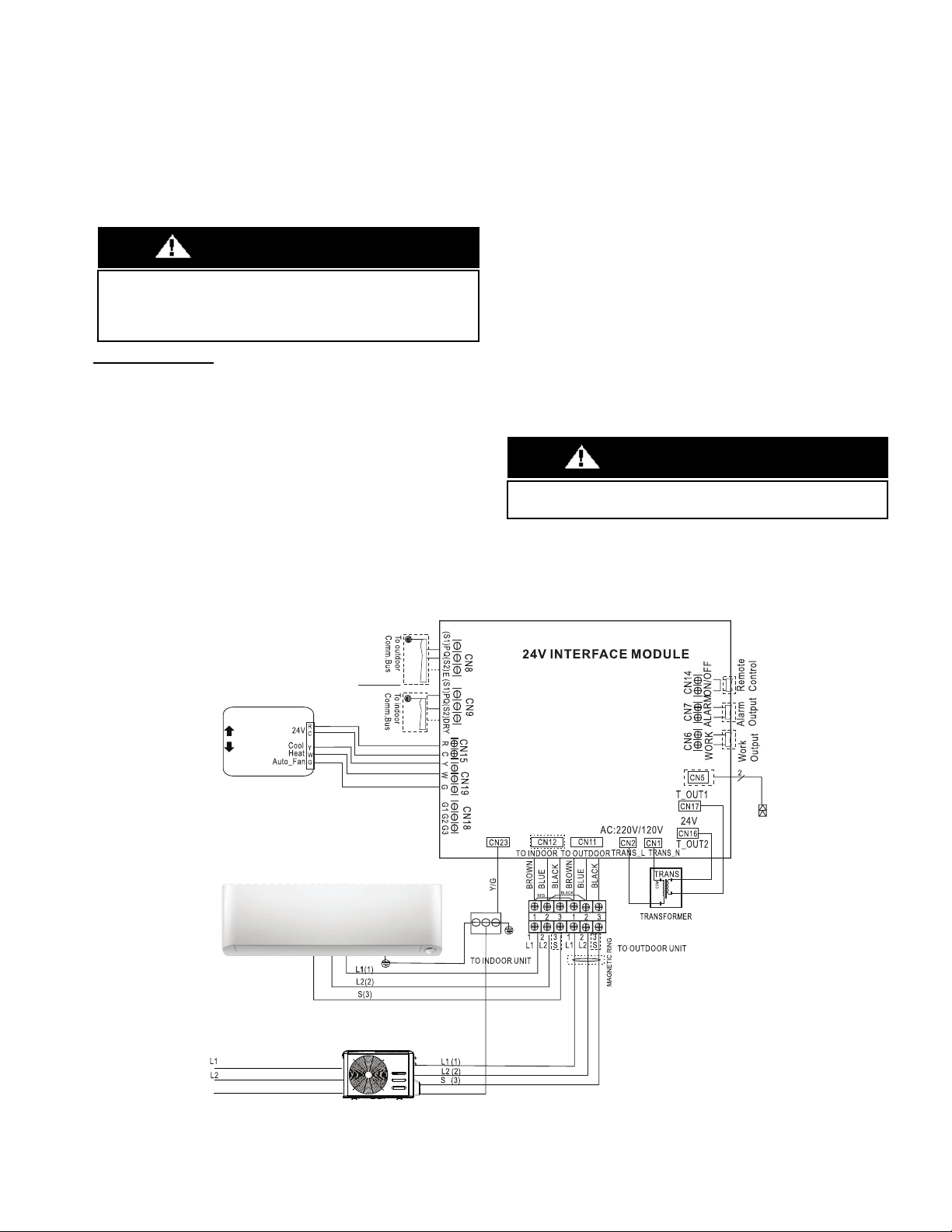
4. Disconnect and remove the 24 volt transformer from the 24 Volt
Interface. Run the 2-conductor 18 AWG cable from R and C of the
indoor unit terminal board. Connect “R” to CN17 and “C” to CN16
on the 24 Volt Interface. Be sure to connect the primary (high
voltage) wire to the correct terminal (tap) on the FV4C transformer
(see “APPENDIX 3 - FV4C TRANSFORMER” on page 16).
5. Run the interconnecting wiring (14-3 AWG stranded power cable with
ground and 600 volt insulation rating) from the outdoor unit to the 24
Volt Interface using terminal connections L1, L2, S, and G. Connect
the ground wire (G) to the grounding connection in the case. Separate
power supplies are required for the outdoor unit and the indoor unit.
6. Run the 18 AWG thermostat wiring from the thermostat terminals
to the 24 Volt Interface and connect to R and C on CN15. Also
connect Y, W, and G on CN19.
NOTE: Use an instrument size flat blade screwdriver
with a maximum blade width of 1/8” for the screw
terminals.
7. Run the 18 AWG thermostat wiring from “G1” on CN18 of the 24
Volt Interface to “G” on the indoor unit terminal board.
8. Install the T1 sensor (included with 24 Volt Interface) on CN5 of the 24 Volt
Interface and locate according to the
NOTE
addressing the indoor and
outdoor unit’s general installation in the next column.
9. Configure the dip switches on the 24V Interface for proper
operation:
For Heat Pump – all switches OFF except SW1-1 = ON
For Cooling Only – all switches OFF except SW1-1 = ON and
SW2-1 = ON.
10. Configure the fan coil “Easy Select” Printed-Circuit Board
following the instructions on the indoor unit’s installation manual.
11. Configure the thermostat to operate as a single stage cooling and
heating (DO NOT configure the thermostat as a Heat Pump).
NOTE:
Follow the indoor and outdoor unit’s general installation instructions.
The T1 (Return Air Temperature) sensor should be near or on the indoor unit
on the air inlet side. The thermistor should be installed pointing down into the
duct between 2.5 ft (0.75 m) and 4 ft (1.2 m) from the return side of the fan
coil. Use a ½” drill and insert the thermistor no less than 6 in (15 cm) into the
duct and seal air tight around the cable.
Auxiliary Heater on an FV4C:
Refer to and follow the steps of the FV4C Fan Coil Installation
Instructions manual:
1. Wire W2 from the thermostat directly to the FV4 fan coil. See
Figure 11 - FV4C Fan Coil Wiring with 1- Speed Heat Pump (page
7) in the FV4C Installation Instructions manual.
Do not remove the jumper on the fan coil between W1 and W2
2. Re-configure the wall thermostat to control the electric heat as a
2nd stage heat W2.
3. Use the FV4 standard molex 12-pin connector to connect the
Auxiliary Electric Heater element.
NOTE:
When an auxiliary electric heater is connected and active by
W2 from the thermostat, the fan coil keeps blowing air regardless if
the outdoor unit is operating under
DEFROST
mode.
Fig. 13 — Wiring Diagram for FV4C Fan Coil Unit
When the outdoor unit is matched with a Residential fan coil and brazing
the piping on the fan coil side is required, it is NECCESSARY to flow
nitrogen into the system while brazing the line set since a filter drier is not
recommended for use with these condensing units.
CAUTION
W2
Thermostat
70
G
G
G
FV4C
Indoor Unit
L1
L2
24V
D
H
R
W
1
W
2
Y
1
YY
1
G
O
C
Dash line
means
disconnect
transformer
Power supply from outdoor unit disconnect.
Two wires are line voltage and the other is a
ground wire.
Power supply from indoor unit
BUS BAR
GROUND

10 Specifications subject to change without notice. IM-KSAIC03-03
TXV REPLACEMENT PROCESS FOR
PIPING ADAPTER FOR FV4CNF002L00 AND
FV4CN(B,F)003L
1. Gain access to the built-in TXV inside the fan coil cabinet.
2. Double-wrench the TXV mechanical connector and disassemble.
3. Cut the bleed line from the TXV to the suction line and braze closed
the capillary tube.
4. Remove the tail bulb from the suction line by cutting the stainless
steel band.
5. Assemble the line set to the piping adapter kit (40MD000003).
Obtain through RCD.
a. Refer to “APPENDIX 2 - PIPING ADAPTER BUSHINGS/
REDUCERS” on page 16 for Bushing/Reducer sizing.
b. Adapt (where needed) and braze the liquid line to the piping
adapter.
6. Place the Teflon gasket on the brass tip of the Piping Adapter and
insert into the aluminum distributor head.
Thread the piping adapter brass nut onto the distributor line and tighten - finger tight + 1/2 turn.
Fig. 14 — Piping Adapter Replacement
BASIC SETUP FOR THE FV4C “EASY SELECT” PRINTED-CIRCUIT BOARD
BASIC FAN COIL CONFIGURATION
The following basic fan coil configuration provides AHRI rated
performance of the heat pump:
A. AUX HEAT KW/CFM −
Select the heater range for the size electric heater installed.
B. AC/HP SIZE −
Select system size installed
For size 12K, select 018 on the board.
For sizes 18K - 36 K, select the nominal connector on the
board.
C. SYSTEM TYPE -
Select system type
D. AC/HP CFM ADJUST −
Select NOM
E. ON/OFF DELAY −
Select 0/90 profile
F. CONTINUOUS FAN −
Select the desired fan speed when the thermostat is set to
continuous fan.
For size 12K, select “MED” Fig. 15 — Detail of FV4C Printed-Circuit Board

IM-KSAIC03-03 Specifications subject to change without notice. 11
WIRING
All wires must be sized per NEC (National Electrical Code) or CEC
(Canadian Electrical Code) and local codes. Use the Electrical Data
table MCA (minimum circuit amps) and MOCP (maximum over
current protection) to correctly size the wires and the disconnect fuse
or breakers respectively. Consult the unit’s installation instructions for
the Electrical Data tables.
For scenarios 1, 2 and 3 Ductless Systems - The main power is
supplied to the outdoor unit; the indoor unit is powered by the 24V
interface.
For scenarios 4 and 5 Conventional Fan Coils - Separate power
supplies are required for the outdoor unit and the indoor unit.
For condensing units with a L1, L2 and S power and
communication wiring - The field supplied 14/3 stranded wire with
ground and a 600 volt insulation rating, power/communication wiring
from the outdoor unit to the 24V Interface Kit, consists of four (4)
wires and provides the power for the 24V Interface. Two wires are line
voltage AC power, one is communication wiring (S) and the other is a
ground wire.
For condensing units with a L1, L2, S1 and S2 power and
communication wiring, the field supplied power wiring 14/2 from the
outdoor unit to the 24V interface consists of three (3) wires and
provides the power for the indoor unit. Two wires are high voltage AC
power and one is a ground wire. To minimize voltage drop, the factory
recommended wire size is 14/2 stranded with a ground.
A separate shielded 16GA stranded control wire copper conductor
only, with a 600 volt rating and double insulated copper wire, must be
used as the communication wire from the outdoor unit to the 24V
interface and the indoor unit.
Wiring between the outdoor unit to 24V Interface Kit is polarity
sensitive. The use of the BX wire is NOT recommended.
Key Considerations When Using a Conventional
Fan Coil
The following steps should be taken when using this device with a
conventional fan coil unit (scenarios 4 and 5):
1. Indoor coil metering device (TXV/Piston) must be removed
2. The 24V transformer in the interface module must be disconnected
3. The refrigerant charge amount may need adjusting, depending on
the pipe size and length. Refer to the outdoor unit’s installation
manual.
4. The maximum airflow should not exceed 400 CFM/Ton.
When the indoor fan coil has its own 24V AC transformer, all four wires
of the 24V Interface kit transformer must be disconnected (see Fig. 17).
The suction and liquid refrigerant lines must be properly insulated to
prevent condensation and energy loss.
Fig. 16 — Wiring
Fig. 17 — Wiring
Control Logic
Table 5 — Conventional Thermostat Connections
Table 6 — Mode Setting
FAN SPEED
For Ductless systems (scenarios 1-3) the fan speed defaults to
AUTO
.
For conventional fan coils (scenarios 4-5), the fan speed can be
selected, refer to “APPENDIX 1 - COMPATIBILITY AND FAN
SPEED WIRING” on page 15. The fan outputs are G1 (1st),
G1+G2 (2nd), and G1+G2+G3 (3rd). For the single fan speed only,
G1 has to be connected.
Use the selection options provided to adjust the airflow supplied to
meet the individual installation needs for such things as noise,
comfort, and humidity removal.
Table 7 — Fan Speed Setting
LEGEND
The conventional thermostat must be configured for use with a single
stage air conditioner (Y output ONLY) and a single stage heating (W)
system.
CAUTION
Connector Purpose
R/C 24VAC Output
Y Cooling
W Heating
GFan
AUX/DRY Aux/Dry Mode
Y W G Aux/Dry Setting Mode
X☆☆ Cooling
X☆X
Heating
XXX
Fan only
☆☆ OFF
XXX X OFF
XX☆DRY Mode (on Ductless Systems)
Unit ON/OFF G Setting Fan Speed
X Auto Fan Speed
Auto Fan Speed
X X Fan OFF
ON
XOFF
☆ON or OFF
Only the approved combinations and fan coil model numbers listed in the
“APPENDIX 1 - COMPATIBILITY AND FAN SPEED WIRING” on
page 15 shall be used to avoid any damages to the fan motor.
The use of a fan coils with a PSC motor is not recommended or approved.
CAUTION

12 Specifications subject to change without notice. IM-KSAIC03-03
DIP SWITCHES CONFIGURATION
The 24V INTERFACE KIT must be configured to operate properly
with the system components with which it is installed. To successfully
configure the system, adjust the DIP Switches to match the
components and functions used.
NOTE: Properly identify the DIP Switch number marked
on the board of the 24V interface as SW1 through SW4
before selecting the options. On each DIP Switch block, the
numbers 1 and 2 are marked.
Fig. 19 — DIP Switch Definitions
DIP Switch 1-1
Used to turn ON or OFF the diagnostic code display LED on the 24V
Interface control board (see Fig. 20).
Table 8 — DIP Switch 1-1
Fig. 20 —LED
DIP Switch 1-2
Use for the indoor unit type selection.
Table 9 — DIP Switch 1-2
NOTES*:
1. Need to remove the indoor unit throttle (piston/TXV/ orifice);
2. The indoor fan stops during the DEFROST mode and starts
again 30 seconds after the defrost cycle is complete on the
outdoor unit. G1, G2 and G3 on the 24V interface will not
provide any fan output signal to the indoor fan during the
DEFROST cycle plus 30 seconds.
NOTE: If this 24V interface is matched with a non-ductless
indoor unit, the DIP Switch must be set to OFF.
DIP Switch 2-1
Use for selection of the system: Cooling Only or Heat Pump.
Table 10 — DIP Switch 2-1
DIP Switch 2-2
Use for freeze protection of the indoor coil (only available on
scenarios 1 through 3).
Table 11 — DIP Switch 2-2
NOTE: Applicable only to the Ductless Style Indoor Heat
Pump units in the HEATING mode.
DIP Switch 3-1
On Ductless systems, Dry is used with thermostats with a Dry
Function output.
Table 12 — DIP Switch 3-1
DIP Switch 3-2
Use to increase the compressor frequency in case the set point has not
been reached after 1 hour or 3 hours of operation. The unit keeps
operating at Variable Speed in both instances.
Table 13 — DIP Switch 3-2
DIP Switch 4-1
Not required (planned for future applications). Select the indoor unit’s
FAN ONLY mode.
Table 14 — DIP Switch 4-1
DIP Switch 4-2
Not required (planned for future applications). Select the indoor unit’s
fan speed (when selecting DIP switch 4-1).
Table 15 — DIP Switch 4-2
NOTE: If the SW4-1 is ON, the SW4-2 takes effect, otherwise the
SW1-2 takes effect.
SW1-1 Result Note
ON Display on
OFF Display off Default
SW1-2 Result Note
ON Sets - Both Ductless Indoor and Outdoor Units
(For Scenarios 1-3)
OFF
Outdoor only (Hybrid Solution) (For Scenario 4)
----- Compatible with other 24V indoor units Fan
Coil/Furnace/Cased Coil
Default
(see
NOTES*
below)
SW2-1 Result Note
ON Cooling Only
OFF Heat Pump Default
SW2-2 Result Note
ON Fan does not stop
OFF Fan stops if the indoor coil temperature is low Default
SW3-1 Result Note
ON Dry Mode
OFF Used on future applications Default
SW3-2 Result Note
ON 1h
OFF 3h Default
SW4-1 Result Note
ON The SW4-2 is available under fan only mode
OFF The SW1-2 is available Default
SW4-2 Result Note
ON Medium fan speed
OFF High fan speed Default

IM-KSAIC03-03 Specifications subject to change without notice. 13
ERROR CODES
For ease of service, the 24V Interface is equipped with a diagnostic code display LED on the control board (ensure the 24V interface is installed
with the directional arrow pointing up to successfully read the error code). Refer to the indoor or outdoor unit’s service manual as listed in
Table 16 for a troubleshooting breakdown.
Table 16 — Error Codes
Display Malfunction and Protection Indication Service Manual Reference
E0 Indoor EEPROM error Indoor Service Manual
E2 Cross-zero detection error Indoor or Outdoor Service Manual
E3 Indoor fan speed malfunction Indoor Service Manual
E4 Indoor room temperature sensor error Indoor Service Manual
E5 Evaporator coil temperature sensor error Indoor Service Manual
EC Refrigerant leak detection system malfunction Indoor or Outdoor Service Manual
F0 Current overload protection Outdoor Service Manual
F1 Outdoor ambient temperature sensor (T4) malfunction Outdoor Service Manual
F2 Condenser coil temperature sensor (T3) malfunction Outdoor Service Manual
F3 Condenser coil temperature sensor (T5) malfunction Outdoor Service Manual
F4 Outdoor unit EEPROM parameter error Outdoor Service Manual
F5 Outdoor fan speed has been out of control Outdoor Service Manual
F6 T2b sensor error Indoor or Outdoor Service Manual
P0 Inverter module (IPM) malfunction Outdoor Service Manual
P1 Over-voltage or under-voltage protection Outdoor Service Manual
P2 Compressor top high temperature protection (OLP) Outdoor Service Manual
P3 Low ambient temperature cut off in heating Outdoor Service Manual
P4 Compressor drive malfunction Outdoor Service Manual
-- Mode conflict (when connected to a multi-zone) Indoor Service Manual
P6 Compressor low-pressure protection Outdoor Service Manual
IN 24V Interface and indoor unit communication malfunction Indoor Service Manual (E1)
0U 24V Interface (indoor unit) and outdoor unit communication malfunction Indoor Service Manual (E1)
00 24V Interface successful power up and in standby Operational Code
01 System operating in cooling mode Operational Code
02 System operating in heating mode Operational Code
03 System operating in fan mode Operational Code
04 System operating in dehumidify mode (not a recommended application for
FV4C units) Operational Code
05 System operating with Auxiliary heater active (not a recommended application) Operational Code

14 Specifications subject to change without notice. IM-KSAIC03-03
WIRING DIAGRAM
Fig. 21 — Wiring Diagram
GLOSSARY:
• Remote Control (CN14): This input may be used to turn the indoor unit on and off remotely by switch or dry contact. If not
used, the terminals must have a jumper in place for the unit to operate.
• Alarm Output (CN7): This is a dry contact that opens and closes based on the system’s alarm status. This is normally a an
open dry contact.
• Work Output (CN6): This contact is a dry contact that opens and closes based on the system’s running or not running
condition.When the thermostat calls for Cool (Y), Heat (W), or Fan (G), the contact closes.
FAN OUTPUTS:
• (G1) Low Fan Speed
•(G1 + G2) Medium Fan Speed
• (G1+ G2 + G3) High Fan Speed
NOTE: For the single fan speed only, G1 has to be connected.
ON ON
NOTE: If the SW4-1 is ON, the SW4-2 takes
effect, otherwise the SW1-2 takes effect.
Dry Mode
Fan Low/Medium/High
BUS BAR

IM-KSAIC03-03 Specifications subject to change without notice. 15
APPENDIX 1 - COMPATIBILITY AND FAN SPEED WIRING
The 24V Interface Kit is compatible with most single stage conventional 24V thermostats matched with the conventional fan coils listed in
Tables 17, 18, and 19. Before installation, check the compatibility of your outdoor and indoor fan coil. Professional installation is
recommended. For Ductless indoor units compatibility, refer to the Compatibility Charts on HVACpartners.com for the proper matches and
serial numbers.
Select Proper Blower Speed For the Fan Coil
Before operating the unit, ensure that the proper blower speed has been selected. Fan speeds are selected manually. Refer to the indoor unit’s
installation manual for instructions on how to change the fan speed and select the taps (see Tables 17, 18, and 19) for the proper matches.
24V Interface Fan Speed Wiring (See “WIRING” on page 11 for Wiring Connections)
G3 is the High Fan Speed terminal and should be connected to the high tap speed inputs at the fan coil.
G2 is the Medium Fan Speed terminal and should be connected to the medium tap speed inputs at the fan coil.
Tap G1 is the Low Fan Speed terminal and should be connected to the low tap speed inputs at the fan coil. The 24V interface may be connected
to a low Tap Speed, based on the indoor unit’s installation instructions.
Table 17 — Compatibility with FMA4 Fan Coils
Table 18 — Compatibility with FMC4 Cased Horizontal Fan Coils
Table 19 — Compatibility with FMU4 Uncased Horizontal Fan Coils
Table 20 — Compatibility with FV4 Fan Coils
Indoor Volt-
Ph@60Hz Kit Number Nominal System
Size MBTUH
Indoor Model
Number
Outdoor Model
Number
Recommended Maximum
Indoor Fan
Speed Tap Number
FMA4
Vertical
Fan Coil
208/230-1 KSAIC0301230
12 FMA4X1800AL 38MAQB12R--3 Tap 1
18 FMA4X1800AL 38MAQB18R--3 Tap 2
24 FMA4X2400AL 38MAQB24R--3 Tap 5
30 FMA4X3000AL 38MAQB30R--3 Tap 2
36 FMA4X3000AL 38MAQB36R--3 Tap 4
Indoor Volt-
Ph@60Hz Kit Number Nominal System Size
MBTUH
Indoor Model
Number
Outdoor Model
Number
Recommended Maximum
Indoor Fan
Speed Tap Number
FMC4
Cased
Horizontal
Fan Coil
208/230-1 KSAIC0301230
12 FMC4Z1800AL1 38MAQB12R--3 Low (Black)
18 FMC4Z1800AL1 38MAQB18R--3 Medium low (Blue)
24 FMC4Z2400AL1 38MAQB24R--3 Medium low (Blue)
30 FMC4Z3000AL1 38MAQB30R--3 Medium high (White)
36 FMC4Z3600AL1 38MAQB36R--3 Medium high (White)
Indoor Volt-
Ph@60Hz Kit Number Nominal System Size
MBTUH
Indoor Model
Number
Outdoor Model
Number
Recommended Maximum
Indoor Fan
Speed Tap Number
FMU4
Uncased
Horizontal
Fan Coil
208/230-1 KSAIC0301230
12 FMU4Z1800AL1 38MAQB12R--3 Low (Black)
18 FMU4Z1800AL1 38MAQB18R--3 Medium low (Blue)
24 FMU4Z2400AL1 38MAQB24R--3 Medium low (Blue)
30 FMU4Z3000AL1 38MAQB30R--3 Medium high (White)
36 FMU4Z3600AL1 38MAQB36R--3 Medium high (White)
Indoor Volt-
Ph@60Hz Kit Number Nominal System
Size MBTUH
Indoor Model
Number
Outdoor Model
Number
Recommended Fan Speed
Wiring and Configuration
FV4
Fan Coil 208/230-1 KSAIC0301230
12 FV4CNF002L00 38MAQB12R--3 Connect G1 on the 24V
interface to G on the fan coil.
Under the configuration taps
for AC/HP CFM ADJUST, the
recommendation is to
select NOM.
Refer to “TXV REPLACEMENT
PROCESS FOR PIPING
ADAPTER FOR
FV4CNF002L00 AND
FV4CN(B,F)003L” on page 10
and “APPENDIX 5 - FV4C
AIRFLOW DELIVERY” on
page 16 for setup.
18 FV4CNF002L00 38MAQB18R--3
24 FV4CNF002L00 38MAQB24R--3
30 FV4CN(B,F)003L 38MAQB30R--3
36 FV4CN(B,F)003L 38MAQB36R--3

Copyright 2020 CAC/BDP D 3300 Riverwood Parkway Atlanta GA, 30339 Edition Date: 03/20 Catalog No. IM-KSAIC03-03
Manufacturer reserves the right to discontinue, or change at any time, specifications or designs without notice and without incurring obligations. Replaces: IM-KSAIC03-02
APPENDIX 2 - PIPING ADAPTER BUSHINGS/REDUCERS
A piping adapter kit 331831-701 (sold through RCD) is required when removing the factory supplied TXV on the indoor unit. The piping
adapter kit for the FV4 is 40MD000003.
APPENDIX 3 - FV4C TRANSFORMER
This transformer is factory wired for 230V AC operation. For 208V AC applications, disconnect the black wire from the 230-V terminal on the
transformer primary side and connect it to the 208V terminal (see Fig. 22).
Fig. 22 — Transformer Connections on FV4C Fan Coils
APPENDIX 4 - ADDITIONAL REFRIGERANT CHARGE FOR CONVENTIONAL
FAN COILS
When matching the FMA4 and FMC/FMU indoor units, the 12K units require 12.4oz. (350g) more refrigerant due to the indoor coil’s size.
No refrigerant addition is necessary for the FV4 (any size).
All the outdoor units are shipped from the factory pre-charged for 25ft. of piping length. See the outdoor unit’s installation instructions for
additional charge requirements on longer piping lengths.
APPENDIX 5 - FV4C AIRFLOW DELIVERY
Table 21 — FV4C Fan Coil Airflow Delivery (CFM) in Heat Pump Only Heating Mode
NOTES:
1. The airflow numbers listed in Table 21 result from the AC, HP CFM ADJUST select jumper set to NOM.
2. Airflow can be adjusted +15% or -10% by selecting HI or LO respectively for all modes except FAN ONLY.
3. Dry coil at 230 volts and with 10KW heater and filter installed.
4. Airflows shown are represented in standard air conditions.
Model Size Bushings/Reducers Required (Field Supplied)
FMA
FMC
12-18 3/4” - 1/2” Suction only
3/8” - 1/4” Liquid
24-36 3/4” - 5/8” Suction only
3/8” - 1/4” Liquid
FMU
FV4
12-18 3/8” - 1/4” Liquid and 3/4” - 1/2” Suction
24-36 3/4” - 5/8” Suction only
OPERATING MODE
UNIT SIZE OUTDOOR UNIT CAPACITY SINGLE SPEED APPLICATION FAN ONLY
HEAT PUMP EFFICIENCY LO MED HIGH
002
012
018
024
525
525
700
350
350
350
380
380
505
470
470
630
003 030
036
875
1050
415
470
630
755
785
945
Other manuals for KSAIC0301230
1
Table of contents
Other Carrier Recording Equipment manuals

Carrier
Carrier CSM Operating instructions

Carrier
Carrier i-Vu XT Installation manual

Carrier
Carrier System Touch Assembly instructions

Carrier
Carrier Fireye NXTSD507HD Owner's manual

Carrier
Carrier KSAIC0301230 User manual

Carrier
Carrier DLS VRF User manual

Carrier
Carrier KSAIF0101AAA User manual

Carrier
Carrier KSAIF0401AAA User manual

Carrier
Carrier 30RBV User manual

Carrier
Carrier System Touch Assembly instructions