PCE Health and Fitness PCE-IVM 3D User manual

launaM
PCE-IVM 3D
PCE Americas Inc.
17 1 Commerce ayW
Suite 8
Jupiter
FL-33458
USA
From outside US: +1
Tel: (561) 320-9162
Fax: (561) 320-9176
www .pce-instruments.com/english
www .pce-instruments.com
PCE Instruments UK Ltd.
Units 12/13
Southpoint Business Park
Ensign way
Hampshire / Southampton
United Kingdom, SO31 4RF
From outside UK: +44
Tel: (0) 2380 98703 0
Fax: (0) 2380 98703 9
Inspection Camera

User Guide
3 Dimensional
Video Microscope
PCE-IVM 3D
PCE Deutschland GmbH
Please read through the User Manual carefully before use
1
CONTENT
Introduction..............................................................................................2
Framework of the microscope system......................................................2
Working principles of the video microscope system................................2
Functions and features.............................................................................3
Parameters & Specification......................................................................3
Instruction of whole machine...................................................................6
Operation and usage.................................................................................8
Errors and dysfunctions diagnosis/analysis:..........................................12
The software can be downloaded here:
https://www.pce-instruments.com/english/download-win_4.htm

1
.
Attentions
1. Do not disassemble the equipment without correct guide otherwise faults
or errors may happen.
2. High voltage inside, be careful, only a qualified person can open it.
3. The optical lens is preset ready for instant use, disassembly is not
recommended.
4. The machine is a sophisticated precise optical instrument, and is
damageable, knock and impact is prohibited.
5. Careful operation is required to avoid damage.
6. Do not use the machine under humidity condition.
7. When the top and bottom halogen lamps are working, they may be hot,
keep yourself/your skin and inflammable materials away from it to
avoid scald or burn or fire.
8. Do not use the machine under oily fuse or dirty conditions.
9. Please pull out the plug when the machine is not in use.
10. Please keep the machine in dry situation when it won’t be used within a
long time.
11. Please note the parameters of the power supply, do not use other brands’
power supply.
To avoid damage during transportation, original package
should be used to protect the sophisticated equipment, if
lost; quality substitute package is required.
WARNING
The display is vulnerable and may be damaged forever should
its interior parts are changed by any means, to avoid which please let
a qualified person to disassemble and fix the machine when faults
and dysfunctions happen.
2
Introduction
Consisting of manual rotating watching device, varifocal microscope, CCD
camera and LCD; PCE-IVM 3D is a 2/3Dimensional manual video
microscope. Besides, it can be connected to PC via the USB2.0 access, which
enables the system more powerful and applicable to wider application range.
Framework of the microscope system
Working principles of the video microscope system
A clear picture of tiny object could be seen through the manual rotating
watching device which will reflect the picture to the main optical lens, then,
such picture would be grabbed and turned into video signal by the CCD
camera, and then, the video signal would turn into a 3D digital picture on the
LCD display, meanwhile, the video signal will be transformed in the signal
transition box and then sent via the USD2.0 access to the computer for
display, picture-grapping, photographing, measuring, saving and printing as
well. The rotating watching device gets a rotating picture of the tested object

3
from an angle of 45°, on the display, the picture will be of 3D effect; take of
the device, the picture showed will be of 2D/normal effect. Users can get the
picture of ideal video effect by turning the zooming ring of the lens section.
Functions and features
1. Ideal 3D effect pictures for users’ comfortable watching without rotating
the tested object, eliminating dead watching angle; 2D/normal effect
picture/watching is also available.
2. Easy to alternate between 2D/normal and 3D watching mode by
adding/taking off the rotating watching device.
3. High resolution CCD camera and LCD, provides clear and vivid picture
effect.
4. All-in-one integration design, smart size, space saving.
5. Simple and easy to operate, users can get 3D effect picture by just rotating
the watching device.
6. With “+” reticle, for measurement and orientation reference.
7. Built-in LED lamp, brightness easy to be adjusted and controlled on the
control panel.
8. Double halogen lamp, provide illumination from top & bottom, free
lightness adjustment.
9. Optional moving carrier plate, easier to move the tested object.
10. USB2.0 access enables the connection to computer for display,
picture-grapping, photographing, measuring, saving and printing as well.
Application:
Electronics (Micro-electronics), mechanism processing, medicine &
biology, metallurgical industry, material analyzing, quality control analysis,
jewelry, education and science research, etc.
Parameters & Specification
1. System magnification: 12X—75X
Remark: System magnification is the ratio of the size of the tested part on
4
the screen to that of the real tested object.
Relevant parameters: magnification of the object lens/CCD ocular, size of
CCD lens/display.
2. Reflection angle of the rotating watching device: 45°
3. Optical object lens of the microscope system:
Focus of the main optical lens: 0.7X-----4.5X
Focus of the CCD ocular: 0.5X
Focus of the entire optical lens: 0.35X----2.25X
Working distance: approx. 30 mm
View range (diameter.)12.5X9.6mm
4. CCD camera:
Size of lens: 1/3 inch.
Display chip: Panasonic
Horizontal visual resolution: 700TVL.
Sensitization area: 3.6×2.7 mm
Video output: 1.0Vp-p 75Ω
Working Voltage: DC 12V
5. LCD display:
Size: 8 inches.
Pixel: 800*600
Lattice proportion: 0.2535×0.2535 mm
Video input: 1.0Vp-p 75Ω
Work power: DC 12V (8W)
6. USB2.0 Display card:
Requirements for computer system:
CPU: Pentium III 800MHZ or above
Operating system: Windows 2000 or Windows XP.
Memory: 256MB above.
Hard disk capacity: 500MB above.
USB access: 2.0
5
Remark: The picture effect will be affected if the PC can not meet the
above settings.
7. Electrical index of the built-in LED lamp
Max. Working voltage: DC 12V
Voltage adjustment range: DC 7.5-10.5V
8. Electrical index of the top/bottom halogen lamp
Power: 10W/12V
9. Moving carrier plate (optional)
Moving mode: moving ball navigating rail
Size of the plate: 180X155X26mm
Moving range: X axis: 75mm Y axis: 55mm
Reticle Graduation: 0.1mm
Connecting dia.: Φ95
10. Working voltage for the whole machine:
Power supply: 100-240V AC 50/60Hz
Base power supply: 100-240VAC 50/60Hz
11. Physical parameters:
Base size: 255X155X64mm (L x W x H)
Vertical pole height: 250mm
Weight for whole machine: approx. 5.5kgs
Notes: All the abovementioned parameters are subject to updates without
prior notice.
6
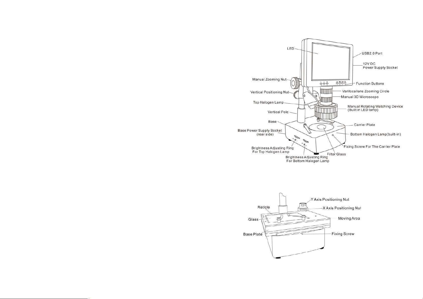
Instruction of whole machine
A. Parts of the whole machine:
B. Parts:
B.1. Moving carrier plate (optional)
(picture 2)

7
B.2. Manual rotating watching device, main lens, CCD camera
B.3. PC port、12V power supply socket
(picture 4)
8
B.4. Function Buttons:
①: Power on/off button of the LCD display screen
②: Power on/off of top halogen lamp/confirming OSD parameters
adjustment
③: OSD menu; enter into OSD menu, and its items and options.
④⑤: Choosing the menu and its item and options.
⑥⑦: Adjusting lightness of the top halogen lamp; choosing items and
options in the menu.
Operation and usage
Installation
a. set the unit on a smooth and solid working table, place the 3-wire socket
in place in the rear side of the unit, then plug intoAC power supply outlet.
b. set the according socket into the “POWER DC 12V” socket and get the
unit electrified.
Turn on/off
a. press button to turn on the display
b. press button to turn off when the unit is wokring.
Attention: Please pull out the plug cut the power supply when the
equipment will not be used for a long time.
1) Adjust the imaging:
place the tested objects on the carrier palte under the lens, adjust the
verifocal to its most magnification, loosen the vertical positioning nut to
(picture 5)

9
adjust the height of microscope and make the distance between the tested
object with the surface of lens is around 30mm, and then turn softly the
manual zooming nut till get the clearest picture
Remarks: the moving carrier plate is recommended to be used to keep
the tested object in right center position.
2) Adjust the magnification:
slightly turn zooming circle of the verifocal lens to adjust the
magnification.
3) 3D imaging:
when the suitable magnification is adjusted ready and the clear picture
effect shows rotating clockwise or counterclockwise, move the tested
object gently, make the rotating picture is in the middle of the screen
(moving carrier plate will do more easily). If the picture effect gets worse
when rotating, gently turn the zooming circle again to make it better.
Remarks: the smaller the magnification is, the wider the view filed of the
scope is, on the contrary, bigger view filed for bigger
magnification.
4) 2D/Normal watching:
Dismantle the watching device by clockwise unscrewing to get
2D/normal watching effect. If the picture is not so clear, gently turn the
zooming circle again to make it better.
5) Adjusting the brightness:
Adjusting brightness of the LED lamp press button “/OK”, the
correspondent mark appears on the right up corner of the screen , and
the lamp is on (direct pressing “+”or “-“ will also turn on the LED lamp).
Once the lightness becomes ideal, press button “/OK”to confirm.
And press button “/OK”again to turn off the LED lamp.
Adjusting brightness of the halogen lamps brightness adjusting rings for
halogen lamps are in the left side of the base of the unit, turn the
corresponding rings to get ideal brightness.
10
6) Adjust the parameters of the image & system setting:
OSD can be adjusted via function buttons. OSD includes “image” and
“settings”.” While “image” includes “brightness”, “contrast”,
“saturation” and “hue”, users can adjust these parameters at their wills.
“Settings” includes “language”, “reticle”, and “reset”.
“language”: 9 languages available.
“reticle”: 10mm for a big graduation of reticle while 5mm for a small
one.
(Notes: the reticle is just for reference only.)
“reset”: recover the factory settings.
Image adjusting:
a. press “MENU” to enter into the sub-menu “image”.
b. press “MENU” again and the option “brightness” is selected and ready
for adjustment
c. to adjust the brightness, press “+” or “-“, to activate other options, press
“▽”or“△”to select.
d. once the options is selected, press “+” or “-“ to adjust.

11
e. when adjustments finish, press button “/OK”to confirm and exit.
System “settings”:
a. press “MENU” to enter into the sub-menu “image”.
b. press “▽”or“△”to enter into sub-menu “settings”.
c. press ”menu”, then option “language” is selected and ready for
adjustment.
d. to change the language, press “+” or “-“.
e. to select “reticle”, press the button“▽”, then the options “on” “off” are
selected, press “+” or “-“ to activate or close “reticle”.
f. to recover the factory settings, press “▽”or“△”to select the option
“reset” thus “”is ready for choice, then press “+” or “-“ to
recover or exit the factory settings.
g. when adjustments finish, press button “/OK”to confirm and exit.
Installation of the USB2.0 display card program and the operation
processes:
12
For installation steps, please refer to “Installation manual of the USB2.0
display card program”.
Errors and dysfunctions diagnosis/analysis:
1. Vague image:
Generally results from the improperly adjusted working distance or the
lens focus, please re-check and make sure the working distance is approx
30mm as required.
2. Image is dim, unclear, colorless, red, and with “snow stains”:
Generally results from weak lightness/brightness, please adjust
lightness/brightness properly strong.
3. Image is too white:
Generally results from strong lightness/brightness, please adjust
lightness/brightness to a properly extent.
4. Image with white spot:
Generally results from refraction of the light beam from the tested object,
please adjust the light incidence and the lightness/brightness to a properly
extent. Normally, scattering light is a better mean of illumination.
5. No image on the video microscope screen:
This may result from many factors, among which the most common two
are display screen dysfunction and signal dysfunction. When this happens,
first, check whether the power supply system is properly working or not;
open the top cover of the machine, if the indicator of CCD camera is on, it
means the power supply system is all right, then the below procedures
should be followed:
(1) Display screen dysfunction: Normally, if the display screen is OK,
press button ①, the caught image or the two-second “no signal”
indication should be on the screen, otherwise display screen
dysfunctions can be deemed affirmative.
(2) No signal dysfunction: When no signals are sent to the display, the
backlight of the display screen will be off even it is power on, so no
image appears on the screen. When this happens, please check the pass
through which the signals are transmitted. Normally, the ocular
microscope is deeded to be ok without outside force, and if the video
signal transmitting wire is ok, then CCD camera will be considered to
arise.

31
Attention:
①If any dysfunction happens to CCD camera or display screen,
please contact thesupplier for repair.
②Please take care of the power supply voltage, wire polarity and the
video format, if users want to change the CCD camera by
themselves.
6. No image on computer screen:
When the screen of the video microscope goes well, but still no image
appears on computer, please check whether the computer works well or
whether the system of the machine and the computer is properly connected
or not, if affirmative answer comes, then the display card dysfunction is
deemed to arise. When this happens, please open the top cover of the
machine and check whether the indicator of the display card is on or not,
and check if the connections between the card and the signal outlet as well
as the video signal input are ok, if yes, then the display card dysfunction is
confirmed to arise. Please contact thesupplier for repair.
Note: High voltage inside, take care, please make sure the electricity is
cut off when checking.
WARNING
The display is vulnerable and may be damaged forever should
its interior parts are changed by any means, to avoid which please let
a qualified person to disassemble and fix the machine when faults
anddysfunctions happen.
PCE Deutschland GmbH
Add: ImLangel 4,59872 Meschede, Germany
(Tel):+49(0)2903/ 976 9920 (Fax):+49(0)2903 / 97699-9920
Website: http://www.pce-instruments.com
E-mail: info@pce-instruments.com
Table of contents
Other PCE Health and Fitness Analytical Instrument manuals


Popular Analytical Instrument manuals by other brands

Virax
Virax VISIOVAL 294020 user guide

Supereyes
Supereyes N012 user manual

FISCHER
FISCHER FISCHERSCOPE X-RAY 5000 Series Operator's manual

Elma Instruments
Elma Instruments Laser 3 manual

Agilent Technologies
Agilent Technologies 83620B 8360 Series Service note

Vivax Metrotech
Vivax Metrotech vCamLS User handbook

Klein Tools
Klein Tools ET510 instruction manual

Anritsu
Anritsu MS2830A Operation manual

JDS Uniphase
JDS Uniphase HP3-60-P4 quick start guide

Terahertz Technologies
Terahertz Technologies VP-150 user guide

Centech
Centech 67979 Owner's manual & safety instructions

MasterForce
MasterForce 244-5968 Operator's manual


