Terahertz Technologies VP-150 User manual

VP-150
Video Scope
Users Guide
Terahertz Technologies Inc. 169 Clear
Road Oriskany, New York 13424
TEL: (315) 736-3642
10/2010

VP-150
Video Scope
Users Guide
10/2010
©Terahertz Technologies Inc.

1
Table of Contents
General Information
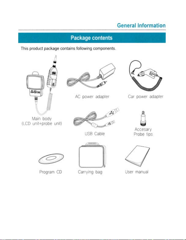
Package Contents 2
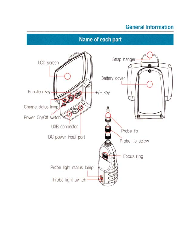
Parts List 3
Basic Operation
Charging the Battery 4
Power On and Off 5
Probe Light 6
Focus Control 7
On Screen Indicator 8
Zoom In / Out 9
Display Brightness 10
Advanced Operations
Laser Light Confirm 11
Computer Connection 12
Computer Software
Software Installation 13
USB Driver Installation 17
Application Software
Operation Method 23
Accessory Setting and Maintenance
Probe Tip Exchange 25
Battery Exchange 26
Safety Information 27
2
3
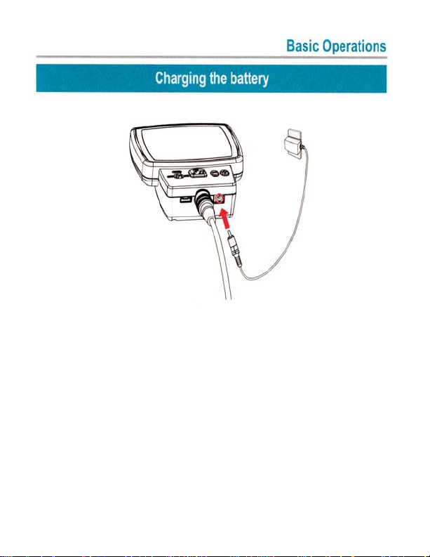
1. Connect battery charger or car power adapter to DC
power input port.
2. It takes about two and one half hours to fully charge the
battery.
3. During charging cycle, the red charge status lamp is on.
When internal batter is fully charged, the indicator lamp
will show green.
4. When the charger connection is removed, the charge
status lamp is off.
4

5
1. Power On/Off switch controls power of main unit. Push
the power switch to on. The LCD screen will light and
the unit operations starts.
2. Push the power switch to off to power off the unit.
6
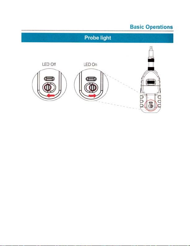
1. When The VP-150 is used for visual inspection test on
fiber optic end face, the probe light should be turned
on. Without the probe light, the fiber optic end
face image cannot be displayed on the LCD screen.
2. Meanwhile, the probe light should be turned off if
the probe is used to detect the presence of laser light.
3. To turn on the probe light, push the probe light switch
to the right . The probe light status indicator will be
illuminated.
4. To turn off the probe light, push the probe light switch
to the left. The probe light status indicator will turn
off.

7
1. When a new target object is examined, usually the dis
play image is out of focus. To focus the image, use the
focus ring on the probe.
2. Turn the focus ring to the right or left until the LCD
displays a clear image.
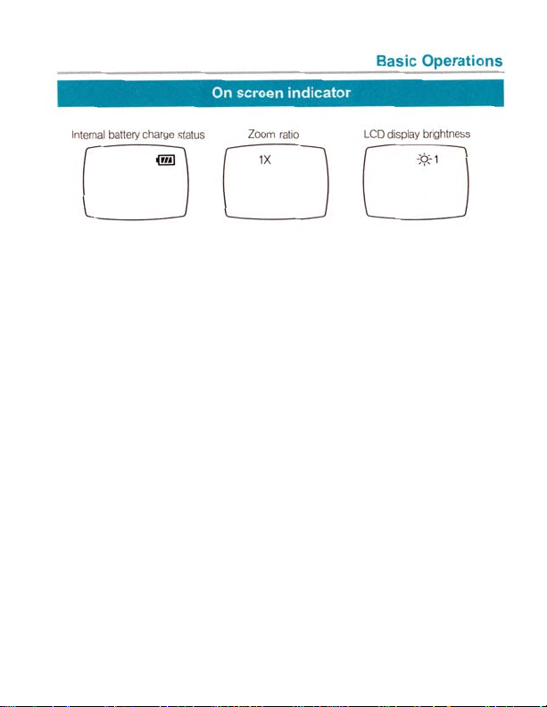
8
Internal Batter Charge Status
Battery charge status icon represents charge status of
internal battery in three steps.
Zoom Ratio
When users adjust zoom ratio value, the current zoom ra-
tio is displayed on the LCD Screen. Zoom Ration Value is
displayed for five seconds after the zoom ratio is changed.
LCD Display Brightness
When users adjust the LCD backlight, the current bright-
ness level value is displayed on the LCD screen. Bright-
ness level value is displayed for five seconds after bright-
ness level value is changed.

9
To adjust zoom ratio, push the Fn Button once. The1.
current zoom ratio will be displayed on the LCD
screen.
To Zoom in, push the + button while the zoom ratio2.
is displayed on the screen. To Zoom out, push the
- button while the zoom ration is displayed. The
Zoom ration has three steps.1X, 2X and 4X. The
current zoom ratio is displayed for five seconds.

10
Brightness level controls the LCD backlight luminance.1. To move the display brightness control mode, press Fn2.
button twice. Then the current brightness level will be
displayed on the LCD screen.
To increase display brightness level, push the + button3.
while display brightness level is displayed on the LCD
screen. To decrease display brightnesslevel,pushthe
- button while display brightness level is displayed on
the LCD screen.
Display brightness level has five steps from 1 to 5. 1 is4.
the darkest, and 5 is the brightest.
Current brightness level is displayed for five seconds.5.
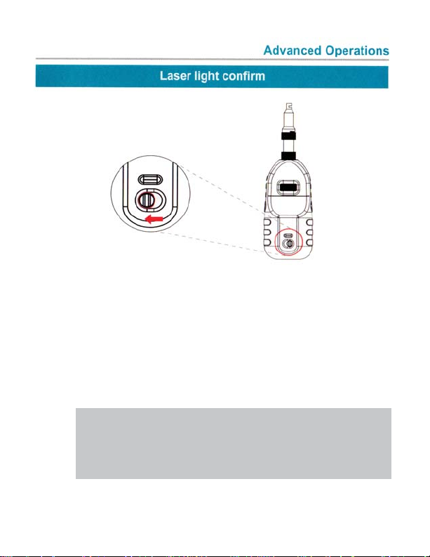
11
The VP-150 can confirm whether the fiber cables or1.
connectors are carrying a laser signal.
In order to confirm whether lase light is present on the2.
cable, the Probe light should be turn off.
Push the probe light switch to the left to turn the probe3.
light off.
LCD will display laser light if signal is present.4.
Note: This is only a quick check and should
not be considered an absolute test to
rule out the presence of laser radiation

12
With the USB Connection, the LCD Screen image can1.
be displayed on computer display. Image capture on
computer is possible by computer software control.
Before connecting the UBS cable to the computer.2.
The software should be installed. Software installation
process will be explained in the computer software
chapter.
Connect the USB cable between VP-150’s USB3.
connector and computer’s USB connector.
The USB connection indication is displayed on the LCD
screen.

13
Software Installation
For proper software installation on computer, discon-1.
nect USB cable between the VP-150 and computer.
Insert Program CD to computer’s CD- ROM Drive.2. Execute “Setup” file on CD3.
14
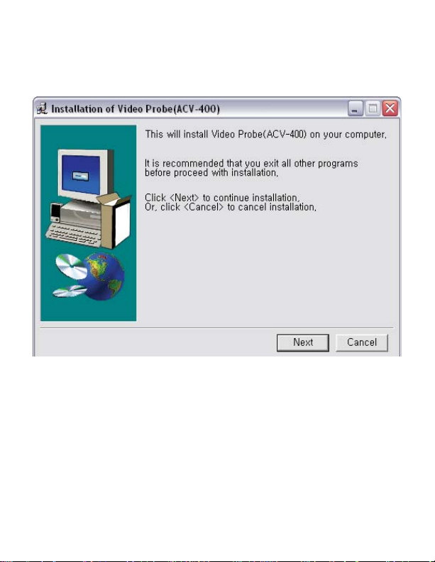
Software Installation
The following window will appear on computer screen.
15
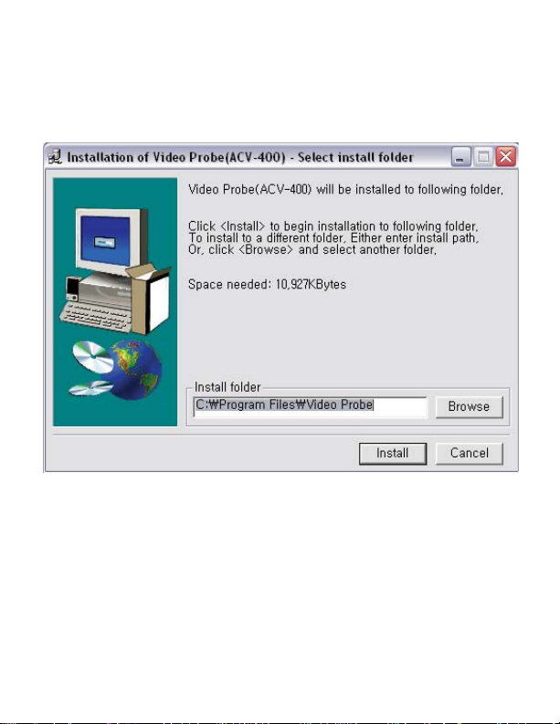
Software Installation
Click nest button and following install folder assignment
screen will appear. Click “Browse” button, select a folder
to which programs will be installed and then click “Install”.

16
Software Installation
The following screen will be displayed.
Click “OK” button and the application program will start if
application software is successfully installed.

17
USB Driver Installation
After Software installation, connect USB Cable be1.
tween VP-150 and the computer.
If the computer automatically detects VP-150 success2.
fully, manual USB driver installation is not necessary.
Otherwise, “Found New Hardware Wizard” will be
started as follows.
Choose “Install from a list or specific location (Advanced)”
and click “Next”

18
Choose “Don’t search, I will choose the driver to install”
and click “Next”
USB Driver Installation
Table of contents


