PCE Health and Fitness LD200 Series User manual

1
Dual Channel Loop Detector
The LD200 is a dual channel inductive loop detector designed for parking
and access control applications.
The detector is connected to an inductive loop mounted in the road
surface. When vehicles pass over the loop the detector switches on an
output.
The use of microprocessor and surface mount technology enables a large
number of functions to be incorporated into a small package. The LD200 is
compatible with most dual channel detectors on the market and is easy to
set-up and install.
Typical applications in the parking and access control environments are safety loops for barriers or gates, arming
loops for activating card dispensers, vehicle counting with direction logic.
Reset Switch. Pressing the reset switch enables the detector to be manually reset during commissioning and
testing. This results in the detector re-tuning the sensing loop and becoming ready for vehicle detection.
Switch selectable Sensitivity. The detect sensitivity is the minimum change in inductance required to produce a
detect output. (%ΔL/L). Eight sensitivity settings are available on the switches to allow flexibility in configuration.
Switch selectable Frequency. The frequency of the loop is determined by the inductance of the loop and the
frequency switch setting. If the frequency switch is on, the frequency is reduced. It may be necessary to change
the frequency to prevent cross-talk between adjacent loops on different detectors.
Selectable N/O or N/C relay output. Internal jumpers enable the output relay contacts to be configured for
normally open or normally closed contacts.
Extend Option. When switched on this feature extends the presence output relay for 2 Seconds after the vehicle
has left the loop.
Direction Logic. This feature enables the detector to give a pulse output on relay1 for a vehicle travelling from
loop1 to loop2 and a pulse output on relay2 for a vehicle travelling from loop2 to loop1. To enable this feature
switches 2 and 4 must be on, and switches 3 and 5 must be off.
Applications
Features
Model –LD200 Series

2
Pulse Relay Selection. The detect relay may be configured for a pulse output, and to energise on detection of a
vehicle or when the vehicle leaves the loop.
Selectable Pulse Time. This feature sets the length of time that the pulse relay will be energised. 1 Second or
0.2 Second.
Power Indicator. This LED Indicator illuminates when power is present.
Detect Indicator. This LED Indicator is illuminated when there is a vehicle over the loop or the loop is faulty. This
LED can also be used to determine the loop frequency. On reset, count the number of times the LED flashes.
Multiply this number by 10KHz.For example: if the LED flashes 6 times, then the loop frequency is between
60KHz and 70KHz.
Loop Fault Indicator. This LED Indicator is illuminated when the loop is either open circuit or short circuit and is
used to give a visual indication of a faulty loop.
Power supply
LD200 200 - 260VAC 50Hz 1.5VA
LD201 100 - 120VAC 60Hz 1.5VA
LD202 11 - 26VAC/DC 50/60Hz 95mA max.
Presence Relay Mode
0.5A/220VAC (Fail Safe –normally energized)
Pulse Relay Mode
0.5A/220VAC(Non Fail Safe–normally denergised)
Response time
Approximately 120ms after vehicle enters loop.
Indicators
LED indicators show: Power, Detect state and Loop Fault.
Detector tuning range
15 - 1500uH
Loop Frequency
Approx. 23 –130KHz (Multiplexing)
Environmental tracking
Automatic Compensation
Protection
Loop isolation transformer with zener diodes and gas discharge tube.
Connector
11 Pin Connector on rear of unit.
Dimensions
80mm (height) X 40mm (width) X 79mm (Depth excl. connector).
Operating Temperature
-40°C to +80°C
Storage Temperature
-40°C to +85°C
Indicators
Technical Specifications

3
LD200 Switch Settings
Switch No.
Function
ON
OFF
10
Presence Relay Extend Time
2 Sec
Off
7,8,9
Sensitivity 0.02%
-
S7/S8/S9
7,8,9
Sensitivity 0.01%
S9
S7/S8
7,8,9
Sensitivity 0.05%
S8
S7/S9
7,8,9
Sensitivity 0.1%
S8/S9
S7
7,8,9
Sensitivity 0.2%
S7
S8/S9
7,8,9
Sensitivity 0.5%
S7/S9
S8
7,8,9
Sensitivity 1%
S7/S8
S9
7,8,9
Sensitivity 2%
S7/S8/S9
-
6
Frequency
Low
High
5
Mode Loop 1 Relay
Pulse
Presence
4
Mode Loop 1 Relay (Pulse Mode)
Undetect
Detect
3
Mode Loop 2 Relay
Pulse
Presence
2
Mode Loop 2 Relay (Pulse Mode)
Undetect
Detect
1
Loop 1 and Loop 2 Relay Pulse Time
1 Sec
0.2 Sec
To select direction logic mode, S2/S4 must be ON and S3/S5 must be OFF.
RELAYS
(Presence or Pulse)
VEHICLE
PRESENT
NO
VEHICLE
LOOP
FAULTY
NO
POWER
PRESENCE
RELAY
N/O
CLOSED
OPEN
CLOSED
CLOSED
N/C
OPEN
CLOSED
OPEN
OPEN
PULSE
RELAY
N/O
PULSE CLOSED
OPEN
CLOSED
CLOSED
N/C
PULSE OPEN
CLOSED
OPEN
OPEN
Switch Settings
Relay Functionality
Output 1 relay
Output 2 relay
N.C.
N.O.
N.C.
N.O.
..
4
SYMPTOM
POSSIBLE CAUSE
SOLUTION
The POWER LED is not
on.
No power supply voltage on
the input.
Check that the power supply is
correctly wired to the detector.
(PINS 1 and 2)
The DETECT LED flashes
erratically.
There may be a poor
connection in the loop or
loop feeder.
The detector may be
experiencing crosstalk with
the loop of an adjacent
detector.
Check all wiring. Tighten screw
terminals. Check for broken wires.
Try changing frequencies using the
frequency switch. Put the detector
with the larger loop onto low
frequency and the detector with the
smaller loop onto high frequency.
The DETECT LED
randomly stays on.
Faulty loop or loop feeder
wiring.
Movement of the loop in the
ground.
Check the wiring. Tighten screw
terminals. Check for pinched or bent
wires. Is the feeder wire twisted?
Check for cracks in the road surface
near the loop.
The LOOP FAULT LED is
flashing.
The loop inductance is too
small or the loop is short
circuit.
Check that there is no short circuit
on the loop feeder wiring or the loop.
If there is no short circuit then the
inductance is to small and more
turns of wire should be added to the
loop.
The LOOP FAULT LED is
permanently illuminated.
The loop inductance is too
large or the loop is open
circuit.
Check that there is electrical
continuity on the loop. This can be
done using a multimeter on the
ohms range (< 5 Ω). If the loop
inductance is too large then try
reducing the number of turns.
Diagnostics
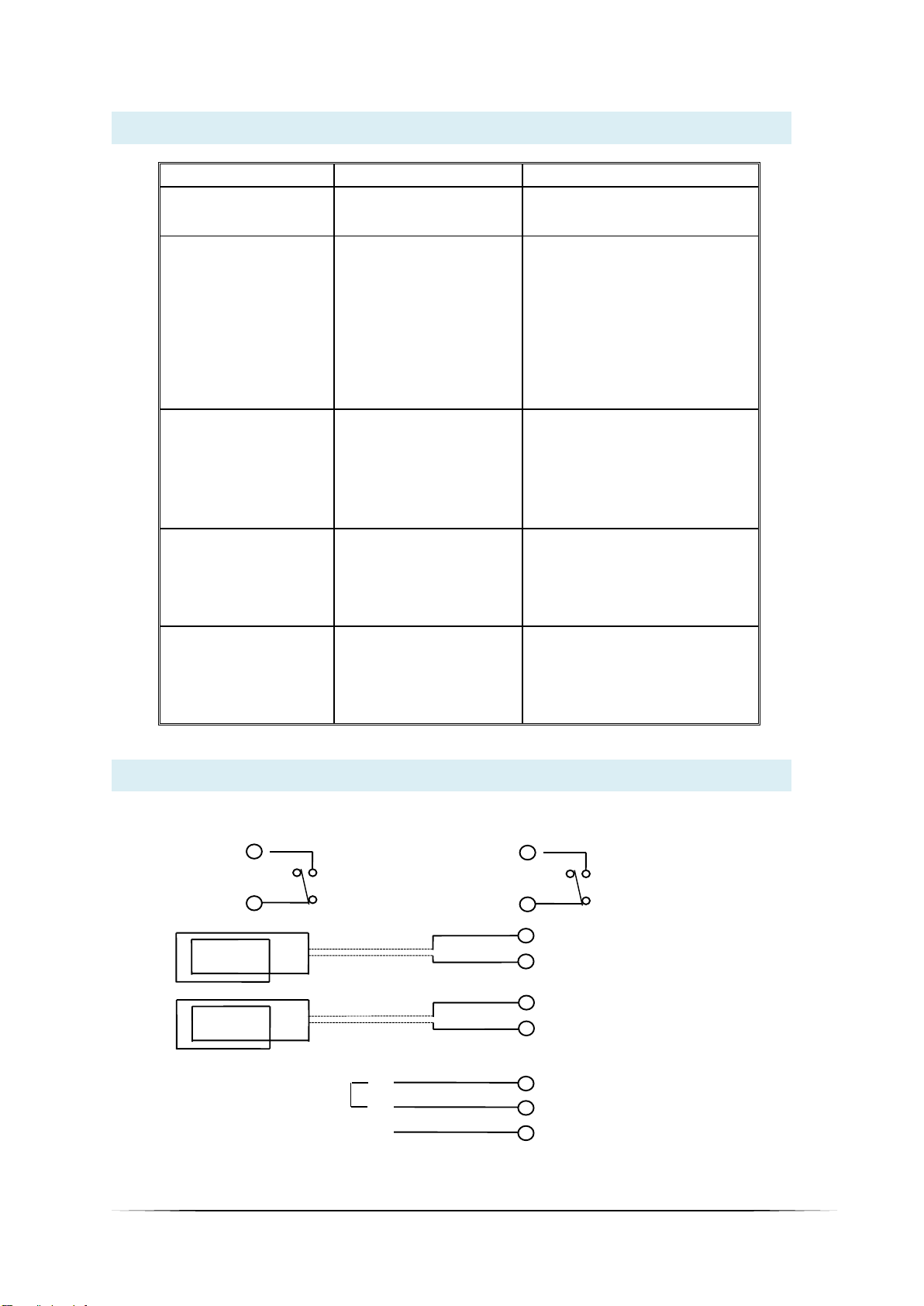
Wiring Diagram
3
LOOP1 INPUT
4
1
2 POWER INPUT
9
LD200 220VAC / LD201 110VAC
LD202 12-24VAC/DC
EARTH
LOOP1
TWISTED
10 7
PRSENCE/PULSE PRESENCE/PULSE
RELAY OUTPUT 1 RELAY OUTPUT 2
11 8
5
LOOP2 INPUT
6
LOOP2
TWISTED

5
1. The detector should be installed in a waterproof housing as close to the loop as possible.
2. The loop and feeder should be made from insulated copper wire with a minimum cross-sectional area of
1.5mm2. The feeder should be twisted with at least 20 turns per metre. Joints in the wire are not
recommended and must be soldered and made waterproof. Faulty joints could lead to incorrect operation of
the detector. Feeders which may pick up electrical noise should use screened cable, with the screen earthed
at the detector.
3. The loop should be either square or rectangular in shape with a minimum distance of 1 metre between
opposite sides. Normally 3 turns of wire are used in the loop. Large loops with a circumference of greater than
10 metres should use 2 turns while small loops with a circumference of less than 6 metres should use 4 turns.
When two loops are used in close proximity to each other it is recommended that 3 turns are used in one and
4 turns in the other to prevent cross-talk.
4. Cross-talk is a term used to describe the interference between two adjacent loops. To avoid incorrect
operation of the detector, the loops should be at least 2 metres apart and on different frequency settings.
5. For loop installation, slots should be cut in the road using a masonry cutting tool. A 45o cut should be made
across the corners to prevent damage to the wire on the corners. The slot should be about 4mm wide and
30mm to 50mm deep. Remember to extend the slot from one of the corners to the road-side to accommodate
the feeder.
6. Best results are obtained when a single length of wire is used with no joints. This may be achieved by running
the wire from the detector to the loop, around the loop for 3 turns and then back to the detector. The feeder
portion of the wire is then twisted. Remember that twisting the feeder will shorten its length, so ensure a long
enough feeder wire is used.
7. After the loop and feeder wires have been placed in the slot, the slot is filled with epoxy compound or bitumen
filler.
Loop Installation Guide
Contact Details
300mm
300mm
1M
ROAD
EDGE
45OCROSSCUT
FEEDER
TRAFFIC DIRECTION
4mm
ROAD SURFACE
30-50 mm
SLOT
SEALANT
WIRES
Refer to our web site for distributor details.
Email: proconel@proconel.com
Web: www.proconel.com
This manual suits for next models
3
Table of contents
Other PCE Health and Fitness Security Sensor manuals

PCE Health and Fitness
PCE Health and Fitness PCE-HFX 100 User manual

PCE Health and Fitness
PCE Health and Fitness LD120 User manual

PCE Health and Fitness
PCE Health and Fitness PCE-LDC 8 User manual

PCE Health and Fitness
PCE Health and Fitness PCE-186 CB User manual

PCE Health and Fitness
PCE Health and Fitness MD360P PUCK User manual

PCE Health and Fitness
PCE Health and Fitness LD213 Series User manual


