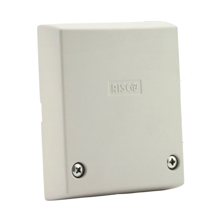
PCE Health and Fitness MD360P PUCK User manual

1 V02
433 MHzWirelessMagnetic Field Vehicle Detector
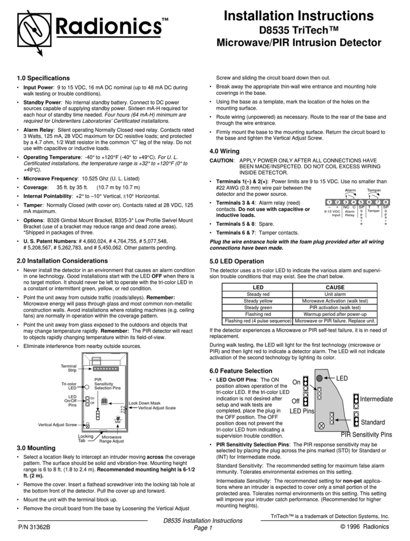
The MD360P (Puck) Combines a magneto resistive sensor with a low power
battery operated radio transceiver. This combination results in
a self-contained wireless vehicle detector that does not
require a loop or any cables to be run to it making installation
times quicker.
The Puck’s sensor detects changes in the earth’s magnetic
field due to the presence of a vehicle, which results in a
detect signal being output to the MD360 Controller.
The Puck has been designed to be buried in the road surface underneath the vehicle path. It is suitable for
installation in any stable surface (bitumen, concrete, compacted earth etc.) and can be easily installed into a
70mm core drilled hole.
The MD360C (Controller) is a wireless control unit which enables
configuration and output of the MD360P. DIP switches are used for
configuration and LED’s are used for visual indication of the operation of the
Puck. A relay output switches ON when a vehicle is detected.
The MD360 series has been designed for parking and access control
applications and is a cost-effective wireless solution for detecting vehicles in
order to facilitate the automatic opening of security gates. It requires a
minimal amount of cutting in the road surface to install.
Wireless connectivity. ● Up to 50 meters range (Line of Sight).
● ETSI EN300-220 Compliant for use in Africa/Australia/Europe/NZ/UK
Battery Life (MD360P only). Up to 5 years battery life @ 25℃(Calculated @ 1 detect per minute).
Reset Switch. ● Reset the Puck from Controller (Puck adjusts to the environment becoming ready for vehicle detection).
●Easily pair Puck to Controller (Note: Only one puck can be paired to a controller at one time).
Switch selectable Sensitivity. Two sensitivity settings are available on the switches to allow for flexibility in
configuration.
Filter Option. Prevent false detection of small or fast-moving objects.
Relay Mode. Configure the relay to operate in presence or pulse mode.
Pulse Relay Selection. Configure relay to pulse on vehicle detect or undetect.
Motion Filter. Only trigger output once the vehicle has stopped moving for at least 1 second.
Presence settings. While in detect, puck will reset after selected timeout: 5min, 30min, 2hr and no-timeout.
Features
Model –MD360P PUCK & MD360C CONTROLLER

2 V02
Power supply
12 - 24VAC/DC 50/60Hz 45mA
Radio Specifications
Frequency: 433.92 MHz
Power: 10 dBm
Modulation: 2FSK
Bandwidth: 250 kHz
Antenna: 1.8 dB Dipole Antenna (Supplied with controller)
Presence/Pulse Relay
Change over contact 0.5A/220VAC
Response time
Approximately 1s after vehicle enters Puck area.
Indicators
LED indicators show: Power, Detect and Reset State.
Connector
5 Way Screw terminal block.
Dimensions
105mm X 90mm X 22mm
Operating Temperature
-20°C to +70°C
Storage Temperature
-40°C to +85°C
Power Indicator. This LED Indicator illuminates when power is present, flashing indicates that the connected
Puck has a low battery voltage.
Detect Indicator. This LED Indicator is illuminated when there is a vehicle present, flashing indicates the device
is in pairing mode.
Reset Indicator. This LED Indicator flashes to indicate that the Puck is currently being reset.
MD360C Switch Settings
Switch
No.
Function
ON
OFF
∞
2hr
30m
5m
10
Presence
On
On
Off
Off
9
Presence
On
Off
On
Off
8
Motion Filter
On
Off
7
Relay Mode
Pulse
Presence
6
Pulse Mode
Undetect
Detect
5
Filter
2 Second
Off
4
Sensitivity
Low
High
3
N/A
2
N/A
1
N/A
Technical Specifications –MD360C (Controller)
Indicators
Switch Settings –MD360C Controller

3 V02
Screw
Terminal
Description
1
Power Supply 0V
2
Power Supply +V
3
Relay Normally Closed N/C
4
Relay Common COM
5
Relay Normally Open N/O
Power
1x 3.6V 9000 mAh Li-SOCL2
Radio Specifications
Frequency: 433.92 MHz
Power: 10 dBm
Modulation: 2FSK
Bandwidth: 250 kHz
Antenna: PCB Trace
Battery Life
Up to 5 years at 1 detect per minute.
Response time
Approximately 1s after vehicle enters Puck area.
Sensing Distance
The Puck should be placed in the ground under the vehicle. Maximum
Sensing distance is 1.5m approximately.
Environmental tracking
Automatic Compensation
Dimensions
Ø 64mm X 38mm
Weight
160g
IP Rating
IP68
Operating Temperature
-20°C to +70°C
Storage Temperature
-40°C to +85°C
Wiring Connections –MD360C Controller
Technical Specifications –MD360P (Puck)

4 V02
The MD360 PUCK has a 1.5m sensing range, best detection results are obtained when the PUCK is mounted
underneath and as close to the vehicles path as possible. The PUCK can be mounted as follows:
1. Buried in the ground alongside the passage of the vehicle.
2. Buried in the road beneath the vehicle.
Note: Battery should face downwards.
It is important that the PUCK does not move during normal operation. Any movement will result in the PUCK
giving a false detection output. It is important to ensure that the tyres going over the PUCK do not put any
downward pressure on the PUCK, any movement of the PUCK will result in a false detection. When burying the
PUCK, ensure that the fill material is concave so that it does not come into contact with the tyre of the vehicle
(See figure 1 below).
Figure 1: Installation of the Puck
Installation steps:
Step 1: Turn on the puck before installing: The puck is shipped in a low power mode, to wake up the
puck place the supplied magnet over the magnet indentation on the top of the puck, after 1s the
magnet can be removed.
Step 2: Install the puck into the road surface: Ensure that the puck is installed within 1,5m of the
vehicles path to ensure correct operation. The puck can be installed into a Ø70mm hole,
ensure that the hole is at least 43mm deep such that the puck is below the road surface.
Secure the puck in place using a suitable sealant.
Step 3: Installing the Controller: Mount the controller into a weatherproof enclosure. Connect wiring as
per wiring connections table. The controller is supplied with a swivel stick antenna, the antenna
can be connected directly to the controller, alternatively a chassis mount antenna could be
installed (1.8dB Gain Max).
Step 4: Pairing the Puck to the Controller: Apply power to the controller and ensure that the power LED
is on. To enter pairing mode, press and hold the reset switch until the detect LED starts flashing
(approx. 10 seconds). When the controller receives a response from a puck whilst in pairing
mode it will automatically pair that puck to the controller. The detect LED will stop flashing when
paired, if the detect LED has stopped flashing but is on, then follow step 5 to reset the puck.
Step 5: Resetting the puck: pressing and holding the reset switch for 2 seconds will cause the puck to
be manually reset, during this stage it is important to ensure that there is no ferrous objects
within the sensing range of the puck. The reset LED will stop flashing once the puck has been
reset. The puck is now ready for use.
Note: Only one puck can be paired to a controller at one time, to change which puck is paired follow
step 4 again. Pairing can take up to 2 minutes for the Puck to respond to the controller.
Installation

5 V02
SYMPTOM
POSSIBLE CAUSE
SOLUTION
The POWER LED is not
on.
No power supply voltage on
the input.
Check that the power supply is correctly wired
to the controller. (Terminals 1 and 2)
The POWER LED is
flashing
The PUCKS battery voltage is
low and will need to be
replaced.
Order replacement MD360P.
The DETECT LED stays
on.
Local environmental change.
Re-calibrate the PUCK by pressing the reset
button.
The DETECT and RESET
LED’s are alternatily
flashing
The Controller has lost comms
with the PUCK. There is
possible radio interference.
Try moving the Controller closer to the PUCK.
The signal range is too
short
This could be due to
attenuation of the signal if the
controller is mounted in a
metal enclosure.
Try changing the antenna direction or relocate
the antenna to the outside of the cabinet using
a relocation kit (not supplied with controller).
Order Code
Description
MD360P
MD360 433MHz Wireless Magnetic PUCK
MD360C
MD360 433MHz Wireless Controller Unit
ANT-433MHZ-KIT
433MHz Antenna Relocation Kit
Diagnostics
Order Codes
Contact Details
Refer to our web site for distributor details.
Email: proconel@proconel.com
Web: www.proconel.com
This manual suits for next models
1
Table of contents
Other PCE Health and Fitness Security Sensor manuals

PCE Health and Fitness
PCE Health and Fitness PCE-186 CB User manual
PCE Health and Fitness
PCE Health and Fitness PCE-LDC 8 User manual
PCE Health and Fitness
PCE Health and Fitness PCE-HFX 100 User manual
PCE Health and Fitness
PCE Health and Fitness LD213 Series User manual
PCE Health and Fitness
PCE Health and Fitness LD200 Series User manual

PCE Health and Fitness
PCE Health and Fitness LD120 User manual
