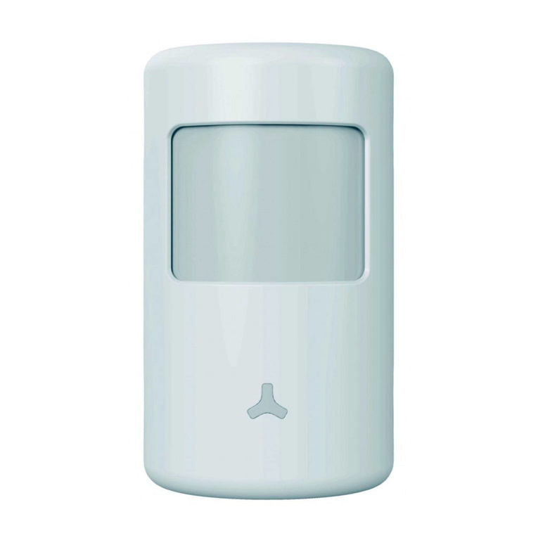
theben HTC thePrema P360-101 UP WH User manual

1
thePrema P360-101 UP WH
2070005
thePrema P360-101 UP GR
2070006
309693
Presence detector
EN
1. Product characteristics
•Passive infrared presence detector for ceiling mounting
•Square detection area 360° (up to 100 m2) for reliable and
easy planning
•Automatic presence- and brightness-dependent control for
lighting and HVAC
•Mixed light measurement suitable for uorescent lamps
(FL/PL/ESL), halogen/incandescent lamps and LEDs
•Light measurement can be switched to spot or wide
measurement
•A channel light: relay, 230V
•Choice of fully or semi-automatic operation
•Adjustable brightness switching value, teach-in function
•Self-learning time delay
•Reduction of switch-off delay time in the event of short
presence (brief-presence)
•Connection option for sensors or switches for manual swit-
ching with automatic recognition of sensor/switch
•Pulse function for staircase light time switch
•Channel H, presence: relay, oating

2
•e.g. for HVAC control
•Switch-on delay and switch-off delay congurable
•Room monitoring with selective movement detection
•Ready for immediate use due to factory preset
•Exceptionally easy conguration of the energy-saving
behaviour with the new «eco plus» function
•Test mode for checking function and detection area
•Extension of detection area via Master/Slave or Master/
Master switching, a maximum of 10 detectors can be swit-
ched in parallel with each other
•Ceiling installation in ush-mounted socket
•Ceiling installation also possible with surface-mounted
frame
•User remote control theSenda S, management remote con-
trol SendoPro (optional)

3
2. Safety
Danger of death through electric shock or fire!
Installation should only be carried out by a pro-
fessional electrician!
WARNING
•Work on electrical systems may only be carried out by
electricians or by instructed persons under the leaders-
hip and supervision of an electrician in accordance with
the technical regulations applying to electricity!
•Comply with the country-specic safety regulations for
work on electrical systems! De-energise cable before
installation!
•The device is maintenance-free. If the device is opened
or penetrated with any objects the guarantee expires.
3. Intended use
The presence detector is intended for interior installation. The
presence detector is exclusively intended for the use as con-
tractually agreed between the manufacturer and the user. Any
other use is considered to be unacceptable. The manufacturer
does not accept liability for any resulting damages.
4. Function
The presence detector is primarily used in ofces and schools,
as well as in homes, for easy and energy-efcient control of
lighting plus HVAC and shading. The switch contact „light“

4
switches lighting on with presence and insufcient brightness,
and off with absence or sufcient brightness. The light can
also be switched on/off manually using push buttons or
switches.
The „presence“ switch contact controls heating, ventila-
tion and air conditioning systems. The contact closes when
someone is present. A switch-on delay allows delayed
switching on. The contact can also be used for room monito-
ring. In this it acts with reduced sensitivity only to signicant
movement.
Functional description
Mixed light measurement
Presence detection
Articial light
Push button for manual lighting control
Incident daylight

5
Doc. Nr. 13056217 Rev.01
15.05.2013 / ZdMa
Settings on thePrema P360-101
Brightness set point value (lux)
Lighting time delay
Presence time delay
Presence switch-on delay
DIP-Switch:
DIP1 Fully automatic/semi-automatic
DIP2 Staircase light function:
room/corridor
DIP3 eco/eco plus
DIP5 Light test: normal operation/test
DIP6 Presence test: normal operation/
Walking test
Mechanical safety lock

6
Light channel
Switching response is controlled by presence and bright-
ness. The switch contact closes during darkness and when
someone is present. It opens with a delay when there is
brightness or when no one is present.
Time delay
The minimum switch-off delay (10 s - 60 min) is adjusta-
ble. It adjusts automatically to the user‘s behaviour and can
increase independently to 30 minutes or reduce back to the
set minimum time. With settings ≤ 2 mins or ≥ 30 mins the
time delay remains unchanged at the set value. If someone
goes into an unoccupied room only briey and leaves it within
30 seconds, then the light shuts off prematurely after 2 minu-
tes (brief-presence).
Push button control
The lighting can be manually switched at any time via a push
button or switch. If the light is switched on manually, the light
will remain on for at least 30 minutes providing people are
present. It then switches off when the brightness is adequate.
The light will go off after a preset time delay if the room is
vacated. If articial lighting is switched off manually. the ligh-
ting remains switched off as long as the room is occupied. The
lighting switches on again automatically after the switch-off
delay has expired.
Fully or semi-automatic
Lighting control via the presence detector operates fully
automatically for increased comfort or semi-automatically for
greater energy savings. In «fully automatic» the lights switch
on and off automatically. Light switching has to be completed
manually in «semi-automatic mode». The lighting is switched
off automatically.

7
Staircase light function
The staircase light function can be set to „room“ or „corridor“
using the DIP switch or the SendoPro management remote
control. Lighting can be switched on and off manually at any
time in the ‚room‘ position. The detector operates as a stair-
case light control in the ‚corridor‘ setting. Manual switch off is
no longer possible.
Exceptionally easy conguration of the energy-saving
behaviour
By selecting “eco” for optimal switching behaviour or “eco
plus” for maximum energy saving, users can adjust the pre-
sence detector to their requirements very easily.
Pulse function
Time delay can be set to pulse for controlling existing stair-
case light time switches. In this every 10 seconds the light
output produces a pulse of 0.5 seconds duration if people are
present or it is dark.
Presence , channel
Channel H, presence, is used for HVAC control or room moni-
toring. The switching behaviour of the oating contact is only
inuenced by presence and not by brightness. If the contact
is closed, the run-on time will be restarted at every movement.
Sensors or switches do not inuence the contact.
Switch-on delay
The switch-on delay prevents instantaneous switch on. The
contact closes only on expiry of the switch-on delay, providing
people are constantly present.

8
Time delay
Switch-off delay enables delayed switching off of HVAC
devices and system after the room is vacated.
Room monitoring
If the switch-on delay is set to monitoring this reduces the
sensitivity of the presence switching output. The contact
closes with signicant movement and indicates the presence
of people with a high degree of certainty. The switch-off delay
remains active. The switch-on delay is inactive.
5. Detection area
The square detection area of the presence detector guaran-
tees accurate and simple planning. Square detection areas
make it possible to cover a whole room with parallel swit-
ching. Note that seated and moving persons can be detected
in differently-sized areas. The recommended installation
height is 2.0 m – 3.5 m. The sensitivity of the presence
detector decreases with higher installation heights. Walking
motions are necessary from installation heights of 3.5 m and
the detection areas of several detectors should overlap in the
marginal zones.
Seated persons:
The presence detector reacts very sensitively to the slightest
movements. The details relate to the reduced detection area
for movements at table height (approx. 0.80 m). The detection
sensitivity is reduced from an installation height of > 3.5 m.
More pronounced movements are required for clear detection.

9
Moving persons:
Use of the whole detection area with low tolerance in margi-
nal area (+/- 0.5 m).
o
stationary persons
moving persons

10
Installation
height
stationary persons moving persons
2.0 m 20 m24.5m x 4.5m 36 m26.0m x
6.0m ± 0.5m
2.5 m 36 m26.0m x 6.0m 64 m28.0m x
8.0m ± 0.5m
3.0 m 49 m27.0m x 7.0m 81 m29.0m x
9.0m ± 1.0m
3.5 m 64 m28.0m x 8.0m 100 m210.0m x
10.0m ± 1.0m
Brightness measurement
The presence detector measures articial light and daylight
that is reected directly below the detector. The character of
the light measurement can be switched via remote control
(„spot“ position, opening angle approx. ± 25°, „wide“, opening
angle approx. ± 45°). The installation site is a reference
point for the lighting level. Brightness measurement can be
adapted to the conditions in a room with the room correc-
tion factor. Direct light inuences the light measurement.
The placement of the oor lamps or suspended lighting
directly below the detector is to be avoided. If the brightness
measurement is deactivated, the light channels only switch
depending on the presence (brightness threshold value set to
„lux on“ via potentiometer or set to „measurement on“ via the
remote control).
Suitable lamps
The presence detector is designed for the operation for
uorescent lamps, compact uorescent lamps, halogen/
incandescent lamps and LEDs. The maximum number of
switchable lights is restricted due to the high switch-on peaks
of the EBs and LED drivers. The use of an external contactor

11
helps with large loads. Parallel switching enables allocation of
load to several Masters. All switched loads must be properly
suppressed.
6. Installation
Flush-mounted installation
The ush-mount installation of the presence detector is done
using a standard UP (ush-mount) installation socket Size 1.

12
Ceiling installation
A ceiling installation unit is available for a simplied ceiling
installation of the presence detector (see accessories). This
ensures strain relief and contact protection at the same time.
The installation diameter is 72 mm (drill diameter 73 mm).

13
Surface-mount installation
A suitable surface-mount frame is available for surface instal-
lation (see accessories).

14
7. Connection
Switching
The presence detectors can be combined as master and slave:
master in individual switching, master in parallel switching,
master-slave parallel switching.
Several push buttons can connected to one control input. Illu-
minated push button switches can only be used with neutral
conductor connection.
Single unit operation
In individual switching, the presence detector as master
detects presence and brightness and controls lighting.

15
AC / DC
H2
H1
L’
Master/slave parallel connection
If the detection area covered by one presence detector is
insufcient (larger rooms), then up to 10 detectors can be
operated in parallel by connecting P terminals. In the process
presence detection is performed by all detectors together.
The master measures the brightness, operates the push but-
tons and controls the lighting. All other detectors are used as
slaves. They only provide presence information.

16
AC / DC
Master Slave
H2
H1
L’
•Light measurement only with the master.
•Parameters are only set on the master.
•Switch up to 10 detectors in parallel.
•Use the phase conductor with the same phase for all
detectors.
Master: thePrema P360 -101
Slave: thePrema P360 Slave, thePrema S360 Slave
Master-Master parallel switching (for several
lighting groups)
Several Masters can be used in parallel switching setup. Each
Master controls its lighting group according to its own bright-
ness measurements. Delay times and brightness switching
values are set individually on each Master. Presence continues
to be detected by all the detectors.

17
AC / DC
Master 1 Master 2
H2
H1
L’
H2
H1
L’
•One Master with individual brightness measurement per
lighting group
•Set parameters and DIP switch individually for each
Master
•Switch up to 10 detectors in parallel.
•Use the phase conductor with the same phase for all
detectors.
•The presence switch contact can be read by any master.
Parallel switching to external staircase light time
switch
One or several presence detectors control a staircase time
switch as master. Their time delay is set to short pulse. When
people are present and there is insufcient brightness their
switch contacts close every 10 seconds for a period of 0.5
seconds and thus restart the time delay of the staircase light

18
time switch.
•Switch light switch contacts of several detectors directly
in parallel.
•Set light time delay in all detectors to short pulse.
•Use the phase conductor with the same phase for all
detectors.
•Staircase automatic system e.g. Theben ELPA 1
34 H2
H1
L’ H2
H1
L’
Presence detectors functioning as staircase light
time switches
As master a presence detector assumes the function of the
staircase light time switch. With the master the DIP switch
is set to «corridor». With every detected movement or push
button activation the time delay is restarted. However the
lights cannot be switched off with the push button. If the
detection area covered by one presence detector is insufci-
ent (larger rooms), then up to 10 presence detectors can be

19
operated in parallel as slaves by connecting P terminals.
•Master switches lighting directly.
•Push button starts the time delay of the master.
•DIP switch to «corridor» prevents switching off with the
push button.
•If needed switch additional slaves in parallel via P
terminals.
•Use the phase conductor with the same phase for all
detectors.
•Potentiometers and DIP switches are only set on the
master.
N
L
H2
H1
L’
Master: thePrema P360 -101
Slave: thePrema P360 Slave
8. Settings
The presence detectors were supplied with basic settings
ready for operation. The specications are guidance values.
Management remote controls are optionally available for
start-up. They enable remote setting of all potentiometer
values and DIP switch settings from a distance.

20
Switch contact light settings
Potentiometer brightness threshold value „Lux“
The brightness setting is made in lux. According to EN 12464
the following values can be set:
•Transit zones (no work area) 150 lux
•Classroom 300 lux
•Work areas (ofce, living room) 500 lux
•Visually-intensive work (laboratory, drawing, etc.) 750 lux
•Deactivation of the brightness measurement “on”
Brightness switch-on values from 5 to 3000 lux can be set
with the management remote control.
Teach-In: the currently measured brightness value can be
applied as the brightness threshold value with the manage-
ment remote control. The lux scale applies for rooms with
average room design. It is recommended that the room
correction factor be adjusted with the management remote
control according to the place of installation, light incidence,
reection characteristics of the room and the furniture.
Table of contents
Popular Security Sensor manuals by other brands
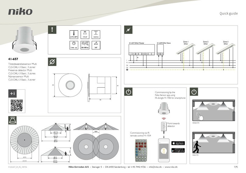
Niko
Niko Multi CLS-DALI-3 Basic quick guide

SPX
SPX Radiodetection RD7100 user guide

LEGRAND
LEGRAND Wattstopper LMPX-100-3 installation instructions
Elektrotechnik Schabus
Elektrotechnik Schabus SHT 240 operating instructions
Smartwares
Smartwares SH4-90157 instruction manual
Aritech
Aritech EV100P Series quick start guide
