PCM Apex Junior User manual

2
Section 1
SETTI NG UP I NSTRUCTI ONS
WARNI NG: ALWAYS ENSURE THAT THE POWER I S DI SCONNECTED BEFORE REMOVI NG
COVER.
a. SETTI NG UP: Load Cells.
The load cell connector is a seven way screw terminal connector:
SCN
Cable Screen
-SE
Negative Sense
+ SE
Positive Sense
-EX
Negative Excitation
+ EX
Positive Excitation
-I N
Negative Signal
+ I N
Positive Signal
NOTE REGARDI NG SENSE TERMI NATI ON
The sense inputs are for use with six wire load cells that have remote voltage sensing in order to
compensate for resistive loss within the cable run. If a load cell is used without this feature then connect the
positive excitation to positive sense and negative excitation to negative sense.
b. SETTI NG UP: Power
i. DC Applications:
N
Positive 6-26v d.c.
E
Ground
ii DC Applicat ions: Battery Versions
B+
Battery Positive
B-
Battery Negative
V+
Adapt or DC (+ 12VDC)
V-
Adaptor Earth
Suitable Charging Adaptor: approx 12vdc@300mA minimum
Correct Procedure to charge unit:
1. With the adaptor AND Junior switched OFF plug the adaptor jack into the unit.
2. Switch on the Adaptor and allow approx 12 hours to fully charge (from a fully discharged state). You can
use the unit whilst in charging mode.
3. Once the charge cycle is complete press and hold the ZERO key to switch off the Junior and sw it ch OFF
the adaptor via the mains outlet.
4. Disconnect the Adaptor jack from the Junior and use normally until the Battery Low indicator is indicated
then complete cycle.
iii. AC Applicat ions: ( 110-240VAC Auto Selection)
DANGER: WARNI NG LI VE TERMI NALS EXPOSED WHEN REAR COVER REMOVED
L
Live 110-240VAC
N
Neutral
E
Earth
Please note: AC power supply automatically senses the mains supply voltage.
3
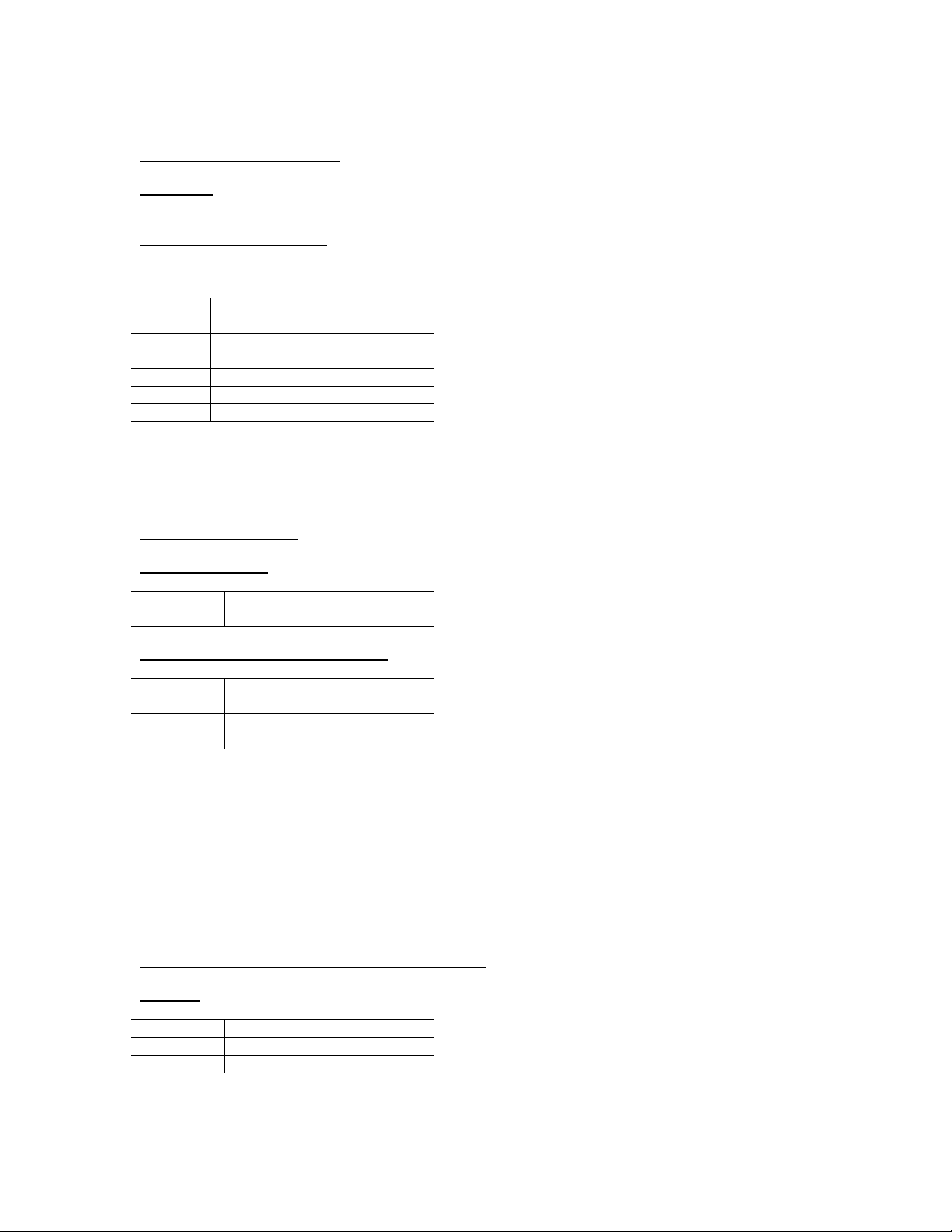
c. SETTI NG UP: SERI AL CONNECTI ONS - Print er
GD
Signal Ground
OP
RS232C Output
I P
RS232C I nput (Busy)
Serial Protocol
RS232C (+ / - 10v)
8 Data Bits
1 Stop Bit
No Parity
Baud Rate: Selectable
ASCII
Printer Requirements:
40 column RS232C compatible.
Common Connections (typical example 25pin D Type – Epson LX300)
Pin 3 (RXD) to OP
Pin 7 ( SG) to GD
Pin 20 (DTR/ Busy) to I P
Please refer to the printer manual for relevant pin descriptions/ terminations.
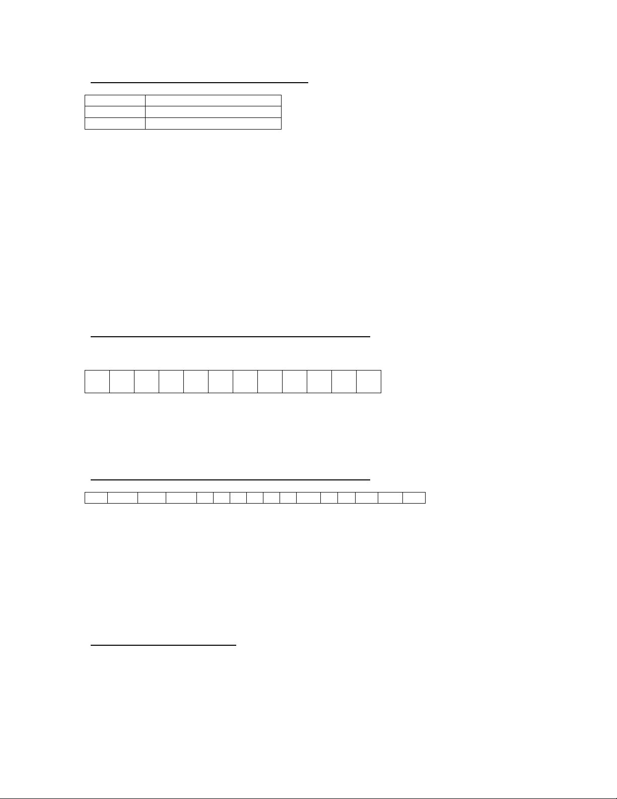
D1. SETTI NG UP: SERI AL CONNECTI ONS - PC Out put ( t ype 1 )
( For details of Hyper-terminal Mode please consult manual G8-WI NDHT-120603)
02 1 2 3 4 5 6 DP K G 0A
O
D
02 = Start
6 digits w eight plus placed decimal point (data MSD to LSD)
Units i.e. kg, g, or te
0A = line feed
0D = Carriage return
D2. SETTI NG UP: SERI AL CONNECTI ONS - PC Output (type 2)
02
N/ G
S/ U
+ / -
1
2
3
4
5
6
DP
K
G
0A
OD
03
02 = Start Message
N/ G = Nett or Gross
S= Stable U= Unstable
+ / -= polarity
6 digit s weight plus placed decimal point ( dat a MSD to LSD)
Units i.e. kg, g, or te
0A = line feed
0D = Carriage return
03 = End of message
e. SETTI NG UP: TI ME AND DATE
Restore power whilst holding PRI NT key pr essed.
Release the POWER key.
I nput 2 digits day/ month/ year/ hour/ minute each entry followed by MODE.
For Example: < M= Mode key> 12M06M03M11M30M = 12/06/ 03 11:30am.
Unit automatically returns to weighing mode.

4
Section 2
CALI BRATI ON.
Press and hold the ZERO key and then press the POWER key, when the display indicate
“888888” release the ZERO key and the display will prompt ‘DP 0000’ and the last
decimal point setting. To alter the decimal point setting press the PRI NT key until the
required position is indicated, once selected press MODE to accept.
The display will now prompt "DIV" and the last minor division increment will be
indicated. To alter this value (possible selections are: 1, 2, 5, 10, 20 or 50) repeatedly
press the PRI NT key until the required value is shown, once selected press MODE to
accept
The display will then briefly prompt “TOP” followed by the last top capacity stored. The
far left digit will indicate “E” showing that the display is in keyboard mode. To clear
existing data press the ZERO key. Press the PRINT key to increment the least significant
digit and press the TARE key to shift the digit to the left i.e. to input a value of 4000
press the PRINT key 4 times and then press the TARE key 3 times. When you have input
the required data press MODE to store the value.
The display will briefly prompt “LOAD” and then indicate ‘E00000’ awaiting the input of
your test load value, at this point check that the platform is empty then enter your
required test load value via the keyboard and press MODE to accept. The display will
now auto null any dead load and raw un-calibrated weight will be indicated. Check that
the display is zero and press the ZERO key if necessary then position the test load onto
the platform, when the display is stable press the MODE key. The display will then
indicate the existing function code for the unit, the MODE key will accept this code or
refer to Menu settings if you wish to amend it. The unit is now calibrated and ready for
use.
Post Trim Calibration
This mode is useful for Silo and large capacity applications.
Switch on the unit whilst holding the MODE key. The unit will work as a standard
weighing machine with no functions. Press the TARE key to increase the displayed
weight value or the PRI NT key to decrease the displayed weight value. Once you have
the correct weight displayed press the MODE key to return to normal weighing mode.
LOADCELL ERROR MESSAGE
I f the display prompts “L-CELL” then the input voltage is outside the working range of
the unit. Check all load cell connections are present and correct.

5
Section 3
MENU SETTI NGS
The unit may be user configured for certain functions this is set via a code input.
To access the code hold the TARE key whilst restoring power, when the display shows 888888
release the TARE key. A 5 digit numeric code number will be displayed prefixed by an alpha
character that records the build version for information purposes only. Refer to the code table for
available functions. To change the settings press the ZERO key in order to clear the existing code
and then input the new code followed by MODE key, note: the unit must have the necessary
hardware options installed if printing or relay functions are selected.
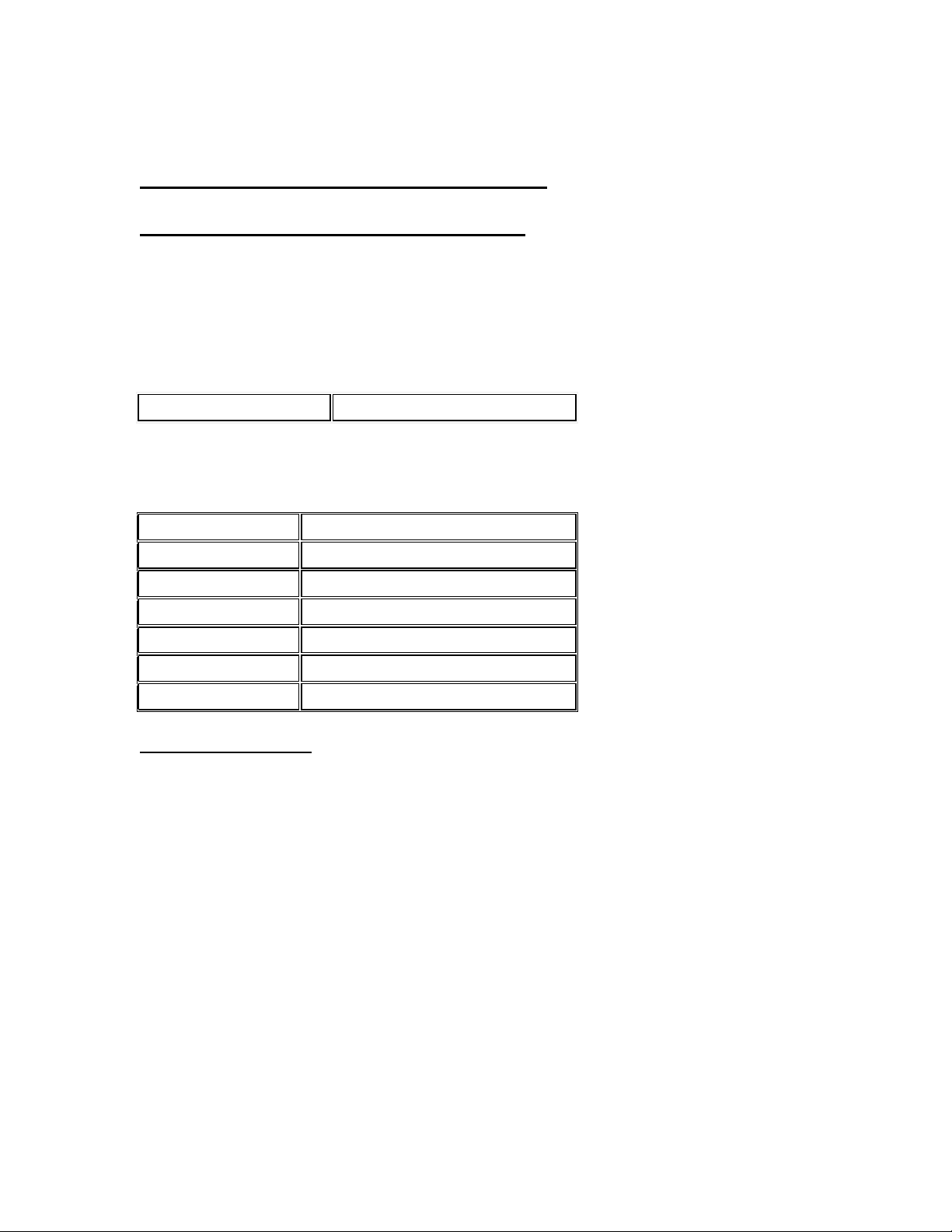
Weigh Mode Print Mode Baud Select Line Feeds Function
0 Standard 0 Nett Kg 0 1200 0 1 0 Standard
N/ Open
1 Count 1 Nett Gm 1 2400 1 2(* ) 1 N/ Open -
Fast
2 Silo 2 Nett Tn 2 9600 2 3 2 N/ Closed
3 Peak 3 G.N.T. Kg. 3 Reserved 3 4 3 N/ Closed-
Fast
4 Manual
Batcher 4 G.N.T. Gm 4 A.E.O. 4 5 4 High/ Low
Limit
5 1 Trip
Batcher 5 G.N.T. Tn 5 Reserved 5 6 5 H.L. Limit
- Fast
6 2 Trip
Batcher 6 P.C. Kg 6 Reserved 6 7 6 Reserved
7 Totalize 7 P.C. Gm 7 Reserved 7 8 7 Reserved
8 Freeze 8 P.C. Te 8 Reserved 8 9 8
Auto
Switch
off
9 Lbs \ kg 9 Reserved 9 Reserved 9 10 9 Reserved
* I f PC output is enabled this selects type 2 data string (see page 3)

6
Section 4
USER I NSTRUCTI ONS
1. STANDARD WEI GH MODE
ZERO: references the display to zero
TARE: the first press of t his key tares the display the second press clears the tare. A symbol in the far left of
the display indicates if a tare is present.
MODE: allows access for preset tare input.
PRI NT: initiates a printout if option fitted. The printout is selectable for nett or gross/ nett/ tare and for units
and linefeeds. A time and date print will also occur if installed. Note the printout will only occur when the
unit is steady and further printouts are inhibited until the load is removed.
POWER: used to switch on the unit, if this key is pressed when the unit is working the display will indicate
the supply voltage, this is useful for battery operation.
2. WEI GH COUNT MODE
Ensure that the indicator displays zero
ZERO: clears any container weights.
Count 10 items onto the platform then press the MODE key. The display should now indicate a count of 10
and further components added will be counted. The ZERO or TARE may be used if required. To return to
weigh mode press the MODE key.
PRI NT: initiates a printout of weight or count depending on mode selection.
Note the sample quantity is default to 10 however if you wish too alter this value press the POWER key and
input the desired quantity (1 to 100).
3. SI LO MODE
This mode inhibits inadvertent zero selection. To zero the display press the ZERO and then MODE key
toget her. Release the ZERO key and then the MODE key
4. PEAK HOLD
To select peak hold mode press the MODE key. Peak weight will then be displayed until the MODE key is
pressed again, the unit will then return to normal weighing.
The PRINT key initiates a printout of weight or peak weight depending on the mode.
Press POWER to view supply voltage.
5. TOTALI SI NG
Press the PRI NT key to add an indicated weight value to the store. Further additions are inhibited until the
display returns to zero. To view the total press the MODE key, press the PRINT key to clear the total or the
MODE key to exit .
If a printer is connected then printout of running number, weights and total will occur. Press POWER to view
supply voltage.
6. FREEZE MODE (Useful for Fork Lift and Animal Weighing Applications)
When a weight above 50 displayed divisions is indicated the unit will initiate a stabilise routine followed by a
locking of the indicated weight value. The display will unlock below 50 indicated divisions. To initiate a re-
weigh in lock mode press the TARE key and when the display shows zero re-press this key. Press the PRINT
key to add an indicated weight value to the store. Further additions are inhibited until the display returns to
zero. To view the total press the MODE key, press the PRINT key to clear the total or the MODE key to exit.
USER NOTE: BATTERY LOW I NDI CATOR
A small dot illuminates in the far left region of the display if the battery voltage is low.
USER NOTE: Display I ndicates “DATA”
To return back to normal weighing mode press the “MODE” key (Version C software onwards).

7
Section 4 Continued…
7. RELAY FUNCTI ONS
The unit may be user configured for several relay options.
Ensure that the necessary hardware options are installed i.e. 1 or 2 relays. The relays are solid state
devices. These relays are rated at a maximum of 100mA at 24vdc. Connections to the relays are via
terminal connections close to t he devices designated 1 & 2 = relay 1 contacts 3 & 4 = relay 2 contacts.
These relays are volt-free contacts unless specified
Three modes of relay control are selectable along with 3 patterns of operation as detailed.
a. Standard Batcher (MENU> WEI GHMODE<code 4: [4000x] )
This allows a batching sequence utilising a single relay control.
Press the MODE key the display will briefly prompt TRIP1” and then the existing value will be shown. To
clear existing data first press the ZERO key to clear the value, the far left digit will show “E” indicating that
the display is in keyboard mode. Press the PRI NT key to increment the least significant digit and press the
TARE key to shift the digit to the left i.e. to input a value of 4000 press the PRI NT key 4 times and then
press the TARE key 3 times.
Repeat the above if Trip 2 is installed.
Ensure that the indicator shows zero by selecting the ZERO or TARE key.
Press the PRINT key to initiate the sequence.
The relay will close and remain closed until the target is reached. I f a tare is selected this will be cancelled,
further batching is inhibited until the display indicates zero. Use of the TARE key to zero the display is
intended for silo batching operations from a loaded silo.
b. One trip bat cher m ode ( MENU> WEI GHMODE<code 5 – AUTOMATI C: [5000x]) .
This mode controls a single relay continuously.
c. Tw o trip bat cher m ode ( MENU> WEI GHMODE<code 6 – AUTOMATI C: [6000x]) .
This mode controls two relays continuously.
RELAY PATTERN SELECTI ON
Refer to the menu code table and menu setting instructions.
3 relay patterns are available and each may include fast or normal integrate speeds.
MENU> FUNCTI ON<code 0/ 1 will operate normally
open
contacts, the relays will
close
if equal too or
greater than trip values.
MENU> FUNCTI ON<code 2/ 3 will operate normally
closed
then
open
if equal too or above the trip
values.
MENU> FUNCTI ON<code 4/ 5 is intended for a low/ high system. Relay 1 is normally
closed
below its trip
value t hen
open
above its trip value and relay 2 is normally
open
below trip value and
closed
at the preset
high level trip value.
8. A.E.O. ( Analogue Expansion Opt ion) : Menu select [00400]
This menu setting relates to the Analogue Expansion Card that, when fitted, will transmit 4-20mA, 0-5vdc or
0-10vdc @ 16bits resolution. This output is an analogue value of the displayed weight. Refer to the data
sheet supplied with the unit for more details.
Correct Procedure to charge unit:
1. With the adaptor AND Junior switched OFF plug the adaptor jack into the unit.
2. Switch on the Adaptor and allow approx 12 hours to fully charge (from a fully discharged state). You can
use the unit whilst in charging mode.
3. Once the charge cycle is complete press and hold the ZERO key to switch off the Junior and sw it ch OFF
the adaptor via the mains outlet.
4. Disconnect the Adaptor jack from th
e Junior and use normally until the Battery Low indicator is indicated
then complete cycle.

8
Section 5
SPECI FI CATI ONS
Display: 6 digits, 18mm high LCD or LED displays
Membrane: Polyester, tactile action.
Enclosure: Splash proof, 165mm x 110mm x 60mm High Grade Stainless Steel.
Operating Temperature: -10 to + 40 degrees C
Load cell Capability: Up to 8 x 300R load cells
Conversion: 24bit Sigma Delta A-D.
I nput Range: 0 – 150mV
Linearity: 0.0015% F.S.
Temperature Drift: 2 p.p.m per degree C
Update Speed: 7ips or 30ips – user selectable
I nternal Resolut ion: 300,000 counts for 10mV input (2mV per volt load cell)
Calibration: Keyboard rout ine.
Pow er ( Mains Opt ion) : Mains version: 75-250vac 50/60Hz Auto Selection.
Pow er ( D.C. Opt ion) : 6-26vdc
Power Consumpt ion: LCD version operating 10mA, LED version operating 130mA. (add 16mA per 300R
load cell)
9
Section 7
EC Declaration of Conformity
E.M.C. STANDARD EN61326 CLASS A
We:
Electronic Weighing Services Lim ited
Of:
Lytton Street, Stoke on Trent. Staffordshire. ST4 2AG
Declare under our sole responsibility that the products:
JUNI OR DWT
EXCELSI OR DWT
To which this declaration relates is in conformity with the following transposing
harmonized standards:
DI RECTI VE
DESCRI PTI ON
EN55022
Radiated Emissions
EN61000-4-4
Fast Burst Transient
EN61000-4-3
Radiated Immunity
EN61000-4-6
Conducted I mmunity
EN61000-4-2
Electrostatic Discharge
2014/ 35/ EU
Low Voltage Safety
R.O.H.S DI RECTI VE
The instruments listed conform to the R.O.H.S directive and is therefore
compliant with the directive.
This declaration is made on the basis of certification and declarations provided to
us from our component suppliers. Under our duty of due diligence these
documents are stored for future audit purposes.
Signed
S.G. Keeling
(Managing Director)
Table of contents


