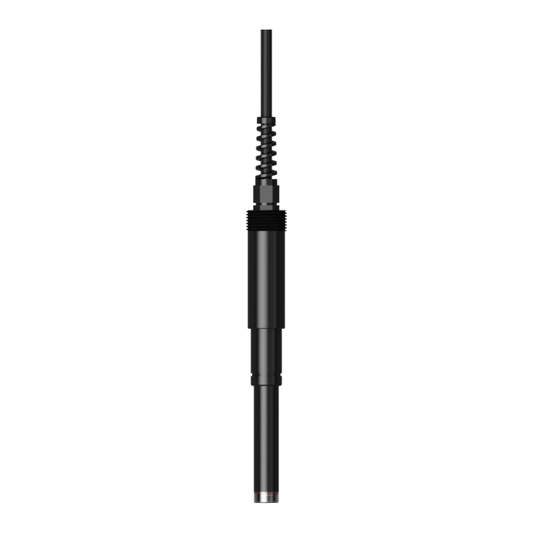
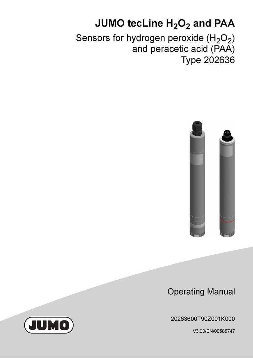
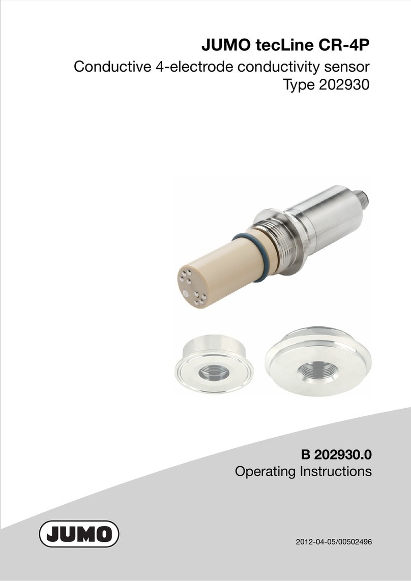
JUMO BlackLine CR 4P User manual

20293100T90Z001K000
V2.00/EN/00743106/2020-08-13
JUMO BlackLine CR 4P
Conductive 4-electrode conductivity sensor
Type 202931
Operating Manual


Contents
Contents
1 Introduction . . . . . . . . . . . . . . . . . . . . . . . . . . . . . . . . . . . . . . . . . . . . . . . . . 4
1.1 Safety information . . . . . . . . . . . . . . . . . . . . . . . . . . . . . . . . . . . . . . . . . . . . . . . . . . . . . . . . .5
1.2 General information regarding the use of the sensor . . . . . . . . . . . . . . . . . . . . . . . . . . . . . .5
1.3 Brief description . . . . . . . . . . . . . . . . . . . . . . . . . . . . . . . . . . . . . . . . . . . . . . . . . . . . . . . . . .6
1.4 Areas of application . . . . . . . . . . . . . . . . . . . . . . . . . . . . . . . . . . . . . . . . . . . . . . . . . . . . . . .6
1.5 Special features . . . . . . . . . . . . . . . . . . . . . . . . . . . . . . . . . . . . . . . . . . . . . . . . . . . . . . . . . .6
1.6 Function . . . . . . . . . . . . . . . . . . . . . . . . . . . . . . . . . . . . . . . . . . . . . . . . . . . . . . . . . . . . . . . .7
1.7 Arrangement of the electrodes in the sensor measuring insert . . . . . . . . . . . . . . . . . . . . . .7
2 Identifying the device version . . . . . . . . . . . . . . . . . . . . . . . . . . . . . . . . . . 8
2.1 Nameplate. . . . . . . . . . . . . . . . . . . . . . . . . . . . . . . . . . . . . . . . . . . . . . . . . . . . . . . . . . . . . . .8
2.2 Order details . . . . . . . . . . . . . . . . . . . . . . . . . . . . . . . . . . . . . . . . . . . . . . . . . . . . . . . . . . . . .8
2.3 Accessories. . . . . . . . . . . . . . . . . . . . . . . . . . . . . . . . . . . . . . . . . . . . . . . . . . . . . . . . . . . . . .9
3 Mounting . . . . . . . . . . . . . . . . . . . . . . . . . . . . . . . . . . . . . . . . . . . . . . . . . . . 10
3.1 General information . . . . . . . . . . . . . . . . . . . . . . . . . . . . . . . . . . . . . . . . . . . . . . . . . . . . . . .10
3.2 Installation suggestions. . . . . . . . . . . . . . . . . . . . . . . . . . . . . . . . . . . . . . . . . . . . . . . . . . . . .10
4 Electrical connection . . . . . . . . . . . . . . . . . . . . . . . . . . . . . . . . . . . . . . . . . 11
4.1 Installation notes . . . . . . . . . . . . . . . . . . . . . . . . . . . . . . . . . . . . . . . . . . . . . . . . . . . . . . . . . .11
4.2 Connection diagram . . . . . . . . . . . . . . . . . . . . . . . . . . . . . . . . . . . . . . . . . . . . . . . . . . . . . . .11
4.3 Connecting cable for CR 4P . . . . . . . . . . . . . . . . . . . . . . . . . . . . . . . . . . . . . . . . . . . . . . . . .12
4.4 Connection to transmitters/controllers . . . . . . . . . . . . . . . . . . . . . . . . . . . . . . . . . . . . . . . . .12
5 Calibrate . . . . . . . . . . . . . . . . . . . . . . . . . . . . . . . . . . . . . . . . . . . . . . . . . . . . 13
5.1 General information . . . . . . . . . . . . . . . . . . . . . . . . . . . . . . . . . . . . . . . . . . . . . . . . . . . . . . .13
5.2 Settings on the transmitter/controller . . . . . . . . . . . . . . . . . . . . . . . . . . . . . . . . . . . . . . . . . .13
6 Maintenance. . . . . . . . . . . . . . . . . . . . . . . . . . . . . . . . . . . . . . . . . . . . . . . . . 14
6.1 Cleaning . . . . . . . . . . . . . . . . . . . . . . . . . . . . . . . . . . . . . . . . . . . . . . . . . . . . . . . . . . . . . . . .14
7 Troubleshooting . . . . . . . . . . . . . . . . . . . . . . . . . . . . . . . . . . . . . . . . . . . . . 15
8 Technical data . . . . . . . . . . . . . . . . . . . . . . . . . . . . . . . . . . . . . . . . . . . . . . . 16
9 China RoHS . . . . . . . . . . . . . . . . . . . . . . . . . . . . . . . . . . . . . . . . . . . . . . . . . 17

4
1 Introduction
1Introduction

5
1 Introduction
1.1 Safety information
General
This manual contains information that must be observed in the interest of your own safety and to avoid
material damage. This information is supported by symbols which are used in this manual as indicated.
Please read this manual before starting up the device. Store this manual in a place that is accessible to
all users at all times.
If difficulties occur during startup, please do not intervene in any way that could jeopardize your warranty
rights!
Warning symbols
WARNING!
This symbol in connection with the signal word indicates that personal injury may occur if the respective
precautionary measures are not carried out.
CAUTION!
This symbol in connection with the signal word indicates that material damage or data loss will occur
if the respective precautionary measures are not taken.
Note symbols
NOTE!
This symbol refers to important information about the product, its handling, or additional benefits.
1.2 General information regarding the use of the sensor
CAUTION!
Incorrect dosage in the event of sudden failure of sensor
The sudden failure of a sensor may result in a dangerous incorrect dosage.
For this case, take appropriate precautionary measures.
NOTE!
It is not permitted to use conductive conductivity sensors in highly adhesive, oily or sticky media —
for these cases we recommend using our inductive conductivity sensors.
If you have any doubts, please contact the nearest branch office or the head office.

1 Introduction
6
1.3 Brief description
The JUMO BlackLine CR 4P acquires the electrolytic conductivity of a measuring liquid according to the
conductive four-electrode measuring principle. When combined with a suitable transmitter, precise mea-
surements over a broad measuring range from 1 µS/cm to 300 mS/cm are ensured. A temperature probe
which is integrated into the sensor (either Pt100 or Pt1000) simultaneously acquires the temperature of
the measuring liquid.
Compared to 2-electrode sensors, this sensor offers a multitude of application-based advantages in the
field and in the lab, and can be used both for measuring purified water and for determining ion concen-
trations in salty, acidic and alkaline media.
The sensor shaft is made from robust PPE, and a high-quality, abrasion-resistant special graphite is used
for the electrode material. All of the materials used are physiologically safe.
The tried-and-tested design, with a 120-mm insertion length, 12-mm shaft diameter and the standardized
Pg 13.5 process connection, enables easy installation in commercially available fittings, and means that
this conductivity sensor can be used, for example, with conventional pH and redox electrodes in corre-
sponding combination fittings.
The sensor is also particularly suited for connection to hand-held and laboratory measuring devices.
1.4 Areas of application
Thanks to its broad measuring range of 1 µS/cm to 300 mS/cm, the sensor is ideal for application in gen-
eral water technology. This means it is possible to reliably measure different levels of conductivity using
just a single measuring system, for example for:
• Cleaning and rinsing processes
• Backwashing in the case of ion exchangers
• Inspecting industrial process waters
• Measuring salt concentration levels
Other liquid analysis application areas include environmental technology, horticultural technology and
fish breeding.
In all application cases, make sure that you comply with the specifications set out in the "Technical Data"
section, and do not use the sensor with highly adhesive, oily or sticky media.
NOTE!
Use in combination with a suitable transmitter/controller, e.g. JUMO AQUIS 500 CR according to data
sheet 202565 or JUMO dTRANS CR 02 according to data sheet 202552 or JUMO AQUIS touch S/P ac-
cording to data sheet 202580/81.
1.5 Special features
• Wide measuring range
(1 µS/cm to 300 mS/cm)
• Suitable for both low and high conductivity
• Reliable and precise measurements
• Reduced sensitivity to pollutants
• No measurement uncertainty resulting from polarization effects
• For universal use
7
1 Introduction
1.6 Function
The measuring sensors have two pairs of electrodes. The transmitter applies alternating current at the
outer pair of electrodes. A voltage is released at the inner electrodes - subject to the conductivity of the
measuring material. The transmitter acquires the voltage and uses it to calculate the electrolytic conduc-
tivity value. Functionally, excitation and measurement are kept separate. This has some advantages
compared to 2-electrode measuring sensors, as the effects of polarization recede into the background.
To a large extent, incoming resistances are automatically compensated. Measurement errors as a result
of contamination or deposits, are reduced.
1.7 Arrangement of the electrodes in the sensor measuring insert
voltage/current
voltage
current/voltage
control
voltage measurement
(1) (4)
(2) (3)
Figure Label Function
A2 Outer electrode 2
I2 Inner electrode 2
A1 Outer electrode 1
I1 Inner electrode 1

8
2 Identifying the device version
2.1 Nameplate
On the sensor
(1) Sensor type (type)
Compare the specifications on the nameplate with your order documents. The supplied sensor version
can be identified using the order code specified under "order details".
(2) Fabrication number (Fab. no.)
The fabrication number provides information such as the production date (year and week). These are
represented by the numbers in positions 12 to 15 (from left).
In the example shown above, the sensor was produced in 2020, in week 30.
(3) Cell constant K
This is where the nominal cell constant of the sensor is specified.
2.2 Order details
(1) Basic type
202931 JUMO BlackLine CR 4P – Conductive 4-electrode conductivity sensor
(2) Basic type extension
10 With internal temperature probe
(3) Measuring insert
1003 1 × Pt100 in two-wire circuit
1005 1 × Pt1000 in two-wire circuit
(4) Electrode material
84 Special graphite
(5) Connection
71 Screw head Pg 13.5 (S8), black, can be rotated
70 Screw head Pg 13.5 with M12 connector
(6) Cable length
0 Without cable (for connection 70)
5000 5000 mm
(7) Insertion length
120.0 120 mm
(1) (2) (3) (4) (5) (6) (7)
Order code /-----
Order example 202931 / 10 - 1003 - 84 - 71 - 5000 - 120

9
2 Identifying the device version
2.3 Accessories
Item Part no.
CR 4P-cable, 5 m, assembled, with M12 connector 00528699
CR 4P-cable, 10 m, assembled, with M12 connector 00528700
CR 4P-cable, 5 m, assembled, with M12 connector,
version for connection to JUMO AQUIS touch
(extended connecting cable for Pt1000)
00502027
CR 4P-cable, 10 m, assembled, with M12 connector,
version for connection to JUMO AQUIS touch
(extended connecting cable for Pt1000)
00502029

10
3 Mounting
3 Moun ting
3.1 General information
Mounting site
• Ensure that the device is easily accessible for calibration later on.
• Make sure that the sensor is mounted securely and with minimum exposure to vibration.
• Ensure that the operating conditions (temperature, pressure, chemical constitution of the medium,
etc.) do not cause damage to the sensor.
• Do not make any mechanical alterations to the sensor (e.g. by shortening it, boring into it, grinding it).
Installation position
The conductivity sensor can be mounted in any position. But it is essential to make sure that the sensor
electrodes are fully immersed in the measurng material.
Incident flow
No incident flow is required to make the conductivity sensor work, but is recommended for fast, stable
measurement values and to prevent the accumulation of deposits. Structural measures must be taken
to prevent flow separation or gas bubbles in the measuring material.
Insertion length
The insertion length of the conductivity sensor must be coordinated with the installation situation.
3.2 Installation suggestions
The sensor can be installed in the following JUMO fittings:
• Flow fittings (product group 202810)
• Combination fitting (product group 202811)
• Immersion fittings (product group 202820)
• Retractable fittings1 (product group 202822)
• Process immersion fitting1 (product group 202821)
• Process fittings1 (Product group 202825/202831)
When installing the sensor, please follow the instructions in the operating manual supplied with the fitting.
NOTE!
When using in the fittings, please observe the permissible limits for the sensor with respect to process
pressure and the temperature of the medium.
1The electrodes of the sensor are located on the inside of the measuring insert (see chapter 1.7 „Ar-
rangement of the electrodes in the sensor measuring insert“). After installing the sensor in the fitting,
it is recommended that you turn the sensor in a manner that ensures that the medium flows through
the measuring insert. This will ensure a fast, reliable measuring process.

11
4 Electrical connection
4.1 Installation notes
4.2 Connection diagram
Type 71 with fixed cable, 6 × 0.14 mm, shielded
Type 70 with M12 connector, 8-pole, A-coded
• Route input, output, and supply lines separately and not parallel to one another
• To connect the conductivity sensor, use the CR 4P-cable (see "Accessories") if possible; do not run
the connecting cable close to current-carrying components or cables
• Implement the cables continuously (not via terminal blocks or similar)
• Do not connect any additional loads to the supply terminals of the sensor
• Follow the instructions regarding the electrical connection in the operating manual for the transmitter
used
• Make sure that you always use safety devices that are independent of the device, and ensure that
only qualified personnel configure the settings. In addition to incorrect installation, incorrectly set val-
ues on the transmitter can impair the performance of the downstream process or cause damage
Figure Wire color Function
Green Pt1000
Yellow Pt1000
Gray Inner electrode 2
Brown Outer electrode 2
White Outer electrode 1
Pink Inner electrode 1
Figure PIN Function
1 Pt100/Pt1000
2 Pt100/Pt1000
3 Inner electrode 2
4 Outer electrode 2
5 Pt100/Pt1000 three-wire circuit
6 Outer electrode 1
7 Inner electrode 1
8Not used

4 Electrical connection
12
4.3 Connecting cable for CR 4P
To connect the conductivity sensor, use only the following cables:
• CR 4P-cable, 5 m, assembled, with M12 connector, part no. 00528699
• CR 4P-cable, 10 m, assembled, with M12 connector, part no. 00528700
• CR 4P-cable, 5 m, assembled, with M12 connector, version for connection to JUMO AQUIS touch
(extended connecting cables for Pt1000), part no. 00502027
• CR 4P-cable, 10 m, assembled, with M12 connector, version for connection to JUMO AQUIS touch
(extended connecting cables for Pt1000), part no. 00502029
For measurement-related reasons, the maximum cable length is restricted to 10 m.
4.4 Connection to transmitters/controllers
The sensor is suitable for connection to the following transmitters/controllers:
NOTE!
Please consult the respective device's operating manual for the necessary information on connecting the
sensor to the aforementioned transmitters/controllers.
M12 cable socket Metal, 8-pole
Cable diameter 7.5 mm
Cable material PUR, blue
Ambient temperature -30 to +80 °C
Cable length 5 m or 10 m
YE
ø7.5
GN
BN
BL
GR
PK
RD
Type Features Data sheet
JUMO dTRANS CR
02
Modular, compact multichannel transmitter and controller with backlit graphic
display for conductivity in the panel housing or surface-mounted housing, 1
main input, 1 analog input, 2 digital inputs, other inputs via optional boards; up
to 3 analog outputs, up to 7 relays
202552
JUMO AQUIS 500 CR Transmitter and controller with backlit graphic display for conductivity, 2 analog
outputs, 2 relays with changeover contacts, comprehensive controller and
switching functions
202565
JUMO AQUIS touch
P/S
Modular multichannel measuring devices for liquid analysis with integrated
controller and paperless recorder, USB host, USB device, Modbus, PROFIB-
US DP, and Ethernet using optional boards
202580
and
202581
JUMO digiLine CR
with separate sensor
Intelligent electronic components for conductive conductivity sensors for auto-
mation systems with JUMO digiLine, IO-Link, analog or binary signals
202762

13
5 Calibrate
5 Calibrate
5.1 General information
Depending on production, the cell constants of commercial conductivity sensors are subject to a certain
level of dispersion. When a more accurate measurement is required, the sensor, measuring line and
transmitter have to be coordinated. This coordination is achieved through calibration.
To achieve optimum accuracy, we recommend performing the calibration in the same conductivity range
in which the measurement will be conducted.
Furthermore, the cell constant of a conductivity sensor can change through ageing and, in particular,
through dirtying of the electrodes (coatings).
That is why it is necessary to clean the sensor and calibrate the transmitter on the conductivity sensor
at regular intervals. The frequency of this depends on the measurement medium and the operating con-
ditions.
NOTE!
Before conducting the calibration, make sure that the sensor is clean and in perfect working condition.
5.2 Settings on the transmitter/controller
NOTE!
For the calibration, it is essential that you observe the operating manual of the transmitter/controller used
(e.g. JUMO AQUIS 500 CR, JUMO dTRANS CR 02, JUMO AQUIS touch S/P or JUMO digiLine CR with
separate sensor).
At least the following settings are required:
• Cell type (connection type): 4-electrode or 4-wire
• Nominal cell constant: 0.51cm-1
Reference solutions
A reference solution is used to calibrate the relative cell constant.
The conductivity of commercial potassium chloride reference solutions include e.g.:
To ensure the measurement is as accurate as possible, the reference solution chosen must be close to
the setpoint of the conductivity measurement when in operation.
When performing the calibration, proceed as instructed in the operating manual for the transmitter/con-
troller used.
1Value for AQUIS 500 CR and dTRANS CR 02; for AQUIS touch and digiLine CR the value 0.25 can
be entered manually for this sensor.
Potassium chloride concentration Conductivity at 20 °C Conductivity at 25 °C
C(KCl) = 0.01 mol/l 1278 µS/cm 1413 µS/cm
C(KCl) = 0.1 mol/l 12.2 mS/cm 12.9 mS/cm
C(KCl) = 3 mol/l 275 mS/cm 298 mS/cm

14
6 Maintenance
6 Mai ntenan ce
6.1 Cleaning
The electrodes of the conductive conductivity sensor come into direct contact with the measurement me-
dium. Therefore, make sure they are cleaned on a regular basis, depending on the soiling tenden-
cy of the measurement medium.
For cleaning, you can use all suitable, common household cleaning chemicals.
Avoid using abrasive cleaning agents.
Ensure that the measuring electrodes do not suffer any mechanical damage.
Cleaning the electrodes in an ultrasonic bath is also good for removing various deposits.
When cleaning, proceed as follows:
• Wipe off minor dirt with a soft, preferably lint-free cloth
• Wash off stubborn dirt and greasy or oily deposits with warm soapy water and a soft brush; you can
also use ethanol to clean the sensor, if necessary
• For calciferous coatings or precipitated metal hydroxides or metal oxides, use diluted hydrochloric
acid (3 % by weight) to dissolve the dirt
•After cleaning, always rinse the sensor with water.
NOTE!
It is not permitted to use conductive conductivity sensors in highly adhesive, oily or sticky media
— for these cases we recommend using our inductive conductivity sensors.

15
7 Troubleshooting
7 Tro ublesh ooti ng
When troubleshooting, all of the components of the conductivity measuring chain must always be taken
into account. As well as the conductivity sensor, also check the transmitter and the connecting cable
used.
You can also check whether the conductivity sensor has suffered a short circuit or has internal contact
problems, see chapter 1.7 "Arrangement of the electrodes in the sensor measuring insert", Page 7, and
chapter 4.2 "Connection diagram", Page 11.
For this you need a continuity tester (e.g. the diode tester of a multimeter).
Error Possible cause Remedy
Measured value too high or too
low
Conductivity sensor dirty Clean conductivity sensor
Transmitter does not show con-
ductivity (e.g. display "0")
Line breakage or incorrect elec-
trical connection
Check electrical connection
Sensor in air (not immersed in
medium)
Check installation location of
sensor
Medium present?
Conductivity displayed on trans-
mitter too high or too low
Electrical connection of sensor
not correct:
Check electrical connection
Poles reversed or incorrect "right
– left" allocation
Transmitter does not display
temperature
Line breakage or incorrect elec-
trical connection
Check electrical connection
Display value unstable, fluctu-
ates
Malfunction due to incorrect/in-
sufficiently shielded connecting
cable
Use CR 4P-cable for connection
Malfunction due to gas bubbles Check line connection and cable
routing
Check the installation location
and installation position of the
sensor

16
8 Technical data
8 Tech ni cal da ta
Measuring principle for conductivity Conductive, 4-electrode measurement
Cell constant K = 0.25 ± 5 %a
Typical measuring rangeb1 µS/cm to 300 ms/cm
Temperature sensor Either Pt100 or Pt1000 (both at least class A)
Response time t90c<96s
Process connection Screw connection Pg 13.5
Materialsd
Sensor body PPE, PS
Electrodes Special graphite
Admissible temperature of medium -5 to +80 °C
Admissible process pressure 6 bar at 80 °C
Protection typeeIP65 and IP67
Electrical connection Either securely connected cable, 5 m long, with tin-plated wire ends, or M12
connector
aThe manufacturing-related deviation of the sensor can be equalized on the transmitter. The measuring accuracy
of the overall conductivity measurement is determined by the transmitter used. Therefore, it is not possible to make
a general assertion as to the accuracy of the measuring system.
bThe measuring range also depends on the transmitter being used.
cDIN EN 60751.
dPlease also refer to the dimensional drawings for the sensors.
eValid for the electrical connection.

17
9 China RoHS
9 C hina R oHS
żżżżżż
;żżżżż
żżżżżż
ż
ℶ❐兓Ⓔ
3URGXFWJURXS
ℶ❐₼㦘⹂䓸德䤓⚜䱿♙⚺摞
&KLQD((3+D]DUGRXV6XEVWDQFHV,QIRUPDWLRQ
捷ↅ⚜䱿
&RPSRQHQW DPH
杔
᧤3E᧥
㻭
᧤+J
柘
᧤&G᧥
⏼ↆ杻
᧤&U9,᧥
⮩䅃勣啾
᧤3%%᧥
⮩䅃ℛ啾搩
᧤3%'(᧥
ཆ༣
+RXVLQJ
*HKlXVH
䗷〻䘎᧕
3URFHVVFRQQHFWLRQ
3UR]HVVDQVFKOXVV
㷪⇽
XWV
0XWWHU
㷪ṃ
6FUHZ
6FKUDXEH
żżżżż
㦻嫷㫋∬㗽^:dϭϭϯϲϰ䤓屓⸩冥Ⓟᇭ
7KLVWDEOHLVSUHSDUHGLQDFFRUGDQFHZLWKWKHSURYLVLRQV6-7
ż᧶嫷䯉年㦘⹂䓸德⦷年捷ↅ㓏㦘⧖德㧟㠨₼䤓⚺摞⧖⦷*%7屓⸩䤓棟摞尐㻑ⅴₚᇭ
,QGLFDWHWKHKD]DUGRXVVXEVWDQFHVLQDOOKRPRJHQHRXVPDWHULDOV¶IRUWKHSDUWLVEHORZWKHOLPLWRIWKH
*%7
î᧶嫷䯉年㦘⹂䓸德咂⺠⦷年捷ↅ䤓㩟⧖德㧟㠨₼䤓⚺摞怔⒉*%7屓⸩䤓棟摞尐㻑ᇭ
,QGLFDWHWKHKD]DUGRXVVXEVWDQFHVLQDWOHDVWRQHKRPRJHQHRXVPDWHULDOV¶RIWKHSDUWLVH[FHHGHGWKH
OLPLWRIWKH*%7


JUMO GmbH & Co. KG JUMO Instrument Co. Ltd. JUMO Process Control, Inc.
Street address:
Moritz-Juchheim-Straße 1
36039 Fulda, Germany
JUMO House
Temple Bank, Riverway
Harlow, Essex, CM20 2DY, UK
6733 Myers Road
East Syracuse, NY 13057, USA
Delivery address:
Mackenrodtstraße 14
36039 Fulda, Germany
Phone:
Fax:
Email:
Internet:
+44 1279 63 55 33
+44 1279 62 50 29
sales@jumo.co.uk
www.jumo.co.uk
Phone:
Fax:
Email:
Internet:
+1 315 437 5866
+1 315 437 5860
info.us@jumo.net
www.jumousa.com
Postal address:
36035 Fulda, Germany
Phone:
Fax:
Email:
Internet:
+49 661 6003-0
+49 661 6003-607
mail@jumo.net
www.jumo.net
This manual suits for next models
1
Table of contents
Other JUMO Accessories manuals

JUMO
JUMO 902454/10 User manual

JUMO
JUMO tecLine Series User manual

JUMO
JUMO 201040 User manual

JUMO
JUMO tecLine ClO2 User manual

JUMO
JUMO tecLine CR-4P User manual

JUMO
JUMO MAERA S29 SW User manual

JUMO
JUMO digiLine CR Series User manual

JUMO
JUMO digiLine O-DO S10 User manual

JUMO
JUMO tecLine ClO2 User manual