Omron F3M-S User manual

AB-288
Features
Detects Transparent Glass Wafers with a
Trans-parency
The F3M-S allows the mapping of cassettes that have both
silicon wafers and glass wafers. Furthermore, the F3M-S ac-
curately detects inexpensive opaque dummy wafers used for
process checks, thus contributing to cost reductions.
Note: Operating conditions are restricted for the detection of transparent wa-
fers. Contact your OMRON representatives for details.
AutomaticTeachingSavesSetting Time Re-
mote Teaching Available
The F3M-S has an automatic teaching function that ensures
easy output adjustments within a minimal time.
Furthermore, the F3M-S has a remote teaching function that
ensures easy output readjustments.
Answerback function during setup and self-
diagnostic function during operation issue
warnings when errors occur!
These alarms contribute to the minimization of system down-
time.
Note: The self-diagnostic output function is not incorporated by the F3M-S826/
-S626.
Prevents Sensor Malfunction and Damage by
OMRON's originaloptical system,including an emitter and re-
ceiver, is built into the F3M-S. This system prevents Sensor
malfunction and damage by protecting the Sensor from static
electricity that may be charged on semiconductor wafers at
the time of mapping.
Ordering Information
Applicable wafer size No. of tiers Functions Model
6 inches (5 inches)
(4.76-mm pitch) 25 F3M-S625
26 --- F3M-S626
8 inches (6.35-mm pitch) 25 F3M-S825
26 --- F3M-S826
12 inches (10-mm pitch) 13 F3M-S1213
25 F3M-S1225
Self diagnostic
Self diagnostic
Self diagnostic
Self diagnostic
Downloaded from Elcodis.com electronic components distributor

AB-289
Rating/performance
* Operating conditions are restricted for the detection of transparent wafers. Contact your OMRON representatives for details.
Item Model F3M-S625 F3M-S626 F3M-S825 F3M-S826 F3M-S1213 F3M-S1225
No. of tiers 25 26 25 26 13 25
Optical axis pitch 4.76 mm 6.35 mm 10 mm
Optical axis width 1.5 mm
Sensing object 6-inch (5-inch) silicon semiconduc-
tor wafer, transparent wafer (work
having 92% or less transparency) *
8-inch silicon semiconductor wafer,
transparentwafer (workhaving 92%
or less transparency) *
12-inch silicon semiconductor wa-
fer, 12-inch sic wafer (work having
30% or less transparency)
Light source
(wave length) Infrared LED (940 nm)
Power supply voltage 12 to 24 VDC ±10%, ripple (p-p) : 10% max.
Current consumption 120 mA max.
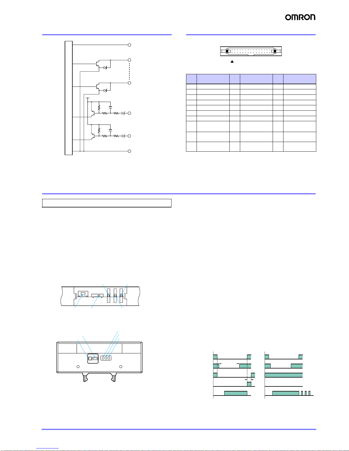
Output
Control
output Load power supply voltage: 30 VDC or less; Load current: 20 mA or less (residual voltage 1 V or less); Input
current: 20 mA; All-channel parallel output, NPN open collector output; DARK: ON
Answer-back output
When remote teaching is ON, pin 28 will be used for this function.
Self-diagnos-
tic output
Load power sup-
ply voltage: 30 V
DC or less; Load
current:20mAor
less (residual
voltage 1 V or
less); Input cur-
rent: 20 mA;
NPN open col-
lector output
---
Load power sup-
ply voltage: 30 V
DC or less; Load
current:20mAor
less (residual
voltage 1 V or
less); Input cur-
rent: 20 mA;
NPN open col-
lector output
---
Load power supply voltage: 30 VDC
or less; Load current: 20 mA or less
(residual voltage 1 V or less); Input
current: 20 mA; NPN open collector
output
Indica-
tor
lamp
P indicator When power is turned on: Illuminates (green)
Warning Illuminates (red) during teaching, when there is no work, when there is insufficient light, and when other problems
occur.
Response time 10 ms max.
Control output
interrupt
When all outputs are stopped: shorts GND and control output stop input (0-V short current: 1 mA or less) When
output stop is canceled: opens GND and control output stop input (open or 9 V or higher, less than or equal to
power supply voltage used)
Remote teaching
input When ON: shorts GND and remote input (0-V short current: 1 mA or less) When OFF: opens GND and remote
input (open or 9 V or higher, less than or equal to power supply voltage used)
Teaching test function
Indicator lamp (orange)
Ambient illuminance Fluorescent lamp: 1,500 lux max.
Ambient temperature Operating: 0 to +40°C, Storage: -25°C to +60°C (with no icing or conden-
sation)
Operating:0°to+55°C,Storage:-25
to +60°C (with no icing or condensa-
tion)
Ambient humidity Operating/Storage: 35% to 85% RH (with no condensation)
Noise resistance
Power supply line:
±
480 V (using normal mode and noise simulator)
Static electrical noise: No malfunction or destruction at ±8 kV
Vibration resistance Destruction: 10 to 55 Hz, 0.5-mm double amplitude for 2 hrs each in X, Y, and Z directions
Shock resistance 300 m/s2, 3 times each in X, Y, and Z directions
Protective structure IEC60529 IP40
Connection method Pull-out cable with connector (standard cable length: 100 mm) Connector
Weight (packed state) Approx. 110 g Approx. 200 g Approx. 300 g
Mate-
rial
Optical axis Polycarbonate
Case ABS ABS, aluminum (Alumite coating,
clear finish)
Cable Vinyl-insulated, bending type ---
Accessories Spacer and instruction manual Instruction manual
Downloaded from Elcodis.com electronic components distributor

AB-290
Output Circuit Diagram Input/output wiring schematic
Pin assignment
* Pin 28 only functions as an answerback output during remote teaching input.
At all other times it functions as a self-diagnostic output, except on the F3M-
S626 and F3M-S826 where it functions as the output of OUT26.
Note: For the F3M-S1213, terminals for pins 16 to 27 are not used.
Precautions
Wiring Considerations
About connection and mounting
The maximum power supply voltage is 24 V DC+10%. Verify
that the power supply voltage does not exceed the maximum
voltage before turning on the power. Use a power supply in
which the secondary circuit is separated by an isolating trans-
former.
●For adjustment
F3M-S6 @and F3M-S8 @
F3M-S12 @
The remote or manual automatic teaching of the F3M-S is possi-
ble with the following two sensitivity settings:
Max. Sensitivity Setting: Detects semiconductor silicon wa-
fers, semi-transparent dummy wa-
fers, and SIC wafers.
Teaching with No Sensing Object: Detects transparent wafers
(except F3M-S12 @).
The sensitivityis set to maximum before shipping. Refer to the
Instruction Manual when setting the sensitivity of the F3M-S.
Answer-back Function and Self-diagnostic
This sensor has a answerback function that warns you of
problemsduring setup and a self-diagnostic function(on mod-
els other than the F3M-S626 and F3M-S826) that warns you
of errors during operation.
• Answer-back Function: Normal or error teaching output
turns
• Self-diagnostic Function: Warning output turns ON for a de-
crease in optical input.
Time chart for manual setup (when teaching without work)
+V
Output
(OUT 1)
Output
(OUT 26) *
Control output
Stop input
Remote teaching input
0V
Main circuit
* With remote teaching input, output becomes answerback output.
And output becomes self diagnostic output except of F3M-S626/F3M-S826.
F3M-S626 and F3M-S826 are outputted from OUT 26.
Pin
No.
Assignment
Pin
No.
Assignment
Pin
No.
Assignment
1GND(0V) 11 OUT9 21 OUT19
2Vcc (12 to 24 V) 12 OUT10 22 OUT20
3 OUT1 13 OUT11 23 OUT21
4 OUT2 14 OUT12 24 OUT22
5 OUT3 15 OUT13 25 OUT23
6 OUT4 16 OUT14 26 OUT24
7 OUT5 17 OUT15 27 OUT25
8 OUT6 18 OUT16 28 Self-diagnostic
output/ OUT26 *
9 OUT7 19 OUT17 29
Control output in-
terrupt
10 OUT8 20 OUT18 30 Remoteteaching
input
2 4 6 8 10 12 14 16 18 20 22 24 26 28 30
1 3 5 7 9 11131517192123252729
Correct Use
Teaching
button
Caution indicator (red)
Teaching indicator (orange)
Power supply indicator (green)
Mode Selector
(RUN/TEACH)
Teaching button
Mode Selector (RUN/TEACH) Caution indicator (red)
Teaching indicator (orange)
Power supply indicator (green)
0.5~2.5s
1s
RUN
TEACH
OPEN
GND
H
L
ON
OFF
ON
OFF
Mode
Selector
Pushed teaching
button
Answer back
function
Teaching indicator
(orange)
Caution indicator
(red)
(Normal) (Error)
Downloaded from Elcodis.com electronic components distributor

AB-291
Dimensions (Unit: mm)
14
10
15
100±
10
1.5
4.76
4.75 135
120.5 (4.76 x 25 + 1.5)
98.6
5120
130
10 5
50
Optical axis
Side mark
Vinyl insulated
bending type Flat cord
Width: 38.1, Pitch: 1.27
(19/0.08 dia.) 30
Connector OMRON
XG4E-3031
Two, 4.2 dia.
(mounting holes)
99
3
52-R4
Teaching button Caution indicator (red)
Teaching indicator (orange)
Power supply indicator (green)
Mode Selector (RUN/TEACH)
18.5
120±
0.2
2-M4
Mounting Dimensions
CAD file F3M_03
F3M-S625
14
10
15
100±
10
1.5
4.76
4.75 135
125.26 (4.76 x 26 + 1.5)
98.6
5120
130
10 5
50
Optical axis
Side mark
Vinyl insulated
bending type Flat cord
Width: 38.1, Pitch: 1.27
(19/0.08 dia.) 30
Two, 4.2 dia.
(mounting holes)
99
3
52-R4
Teaching button Caution indicator (red)
Teaching indicator (orange)
Power supply indicator (green)
Mode Selector (RUN/TEACH)
18.5
120±
0.2
2-M4
Mounting Dimensions
Connector OMRON
XG4E-3031
CAD file F3M_04
F3M-S626
F3M-S825
14
10
15
100
±
10
1.5
6.35
4.875
170
160.25 (6.25 x 25 + 1.5)
118.6
5160
170
10 5
50
Optical axis
Side mark
Vinyl insulated
bending type Flat cord
Width: 38.1, Pitch: 1.27
(19/0.08 dia.) 30
Two, 4.2 dia.
(mounting holes)
20
20 35
2-R5
Teaching button Caution indicator (red)
Teaching indicator (orange)
Power supply indicator (green)
Mode Selector (RUN/TEACH)
18.5
16
±
0.2
2-M4
Mounting Dimensions
Connector OMRON
XG4E-3031 equivalent
CAD file F3M_01
14
10
15
100±10
1.5
6.35
4.875
18.5
175
166.6 (6.35 x 26 + 1.5)
118.6
5160
170
10 5
50
Optical axis
Side mark
Vinyl insulated
bending type Flat cord
Width: 38.1, Pitch: 1.27
(19/0.08 dia.) 30
(5)
Two, 4.2 dia.
(mounting
holes)
20
20 35
2-R5
Teaching button Caution indicator (red)
Teaching indicator (orange)
Power supply indicator (green)
Mode Selector (RUN/TEACH)
160±0.2
2-M4
Mounting Dimensions
Connector OMRON
XG4E-3031 equivalent
CAD file F3M_02
F3M-S826
Downloaded from Elcodis.com electronic components distributor

AB-292
CAD file F3M_05
F3M-S1213
Optical axis
50
14.4
10
7.8
20.3
Two, M4 depth: 8 (mounting holes)
17.7
19.5
17.8
16.2
15.3
19.6
70
25
18
P = 10
Optical axis
1.5
Connector OMRON
XG4A-3034
10
Optical axis
13
140 15
9
8.2
10 x 13 = 130
Teaching button
Mode Selector
(RUN/TEACH) Caution indicator (red)
Teaching indicator (orange)
Power supply indicator (green)
Optical axis
50
14.4
10
Two, M4 depth: 8 (mounting holes)
17.7
19.5
17.8
19.6
70
25
18
P = 10
Optical axis
1.5
Connector OMRON
XG4A-3034
10
Optical axis
13
260 15
9
8.2
10 x 25 = 250
Teaching button Caution indicator (red)
Teaching indicator (orange)
Mode Selector
(RUN/TEACH)
Power supply indicator (green)
7.8
20.3
16.2
15.3
CAD file F3M_06
F3M-S1225
Downloaded from Elcodis.com electronic components distributor
This manual suits for next models
6
Table of contents
Other Omron Accessories manuals

Omron
Omron FQ User manual

Omron
Omron ZFX-C Installation manual

Omron
Omron ZX Series User manual

Omron
Omron E3FS-10B4 2M User manual

Omron
Omron ZFV-C Installation manual

Omron
Omron E3X-DAC-S Series User manual

Omron
Omron E32-L25T User manual

Omron
Omron F3W-D052C Series User manual

Omron
Omron ZFV-CA50 User manual

Omron
Omron ES1 N Series User manual

Omron
Omron V680-HAM91 User manual

Omron
Omron D6T Series User manual

Omron
Omron E3C-LDA - 3 User manual

Omron
Omron E39 Series User manual

Omron
Omron F10 User manual

Omron
Omron fh series Instruction Manual

Omron
Omron Z550 User guide

Omron
Omron E2FM - User manual

Omron
Omron E2Q2 User manual

Omron
Omron E3S-C - User manual