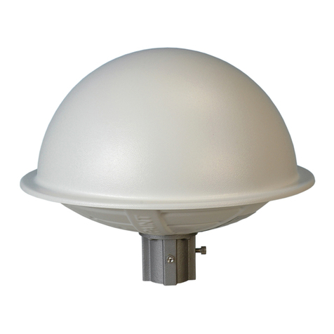
PCTEL VENU MPMI2458 Quick start guide

471 Brighton Drive
Bloomingdale, IL 60108
MPMI2458 Mount
© 2014 PCTEL, Inc.
All Rights Reserved
PRODUCT WARRANTY
GENERAL WARRANTY. PCTEL, Inc. (“PCTEL”) warrants that the PCTEL antenna products
furnished herewith shall be free from defects in material and workmanship for a period of two
(2) years from the date of shipment by PCTEL under normal use and operation; provided,
however, that (a) MPRC and MPRD parabolic reector antennas, Bluewave series antennas,
and PCTEL bulk cable products are similarly warranted for ve (5) years from the date of
shipment by PCTEL; (b) PCTEL enclosure and coaxial cable assembly products are similarly
warranted for one (1) year from the date of shipment by PCTEL; and (c) PCTEL data line
surge and PCT series coaxial surge products are similarly warranted for ten (10) years from
the date of shipment by PCTEL. PCTEL’s sole and exclusive obligation under the foregoing
warranty shall be, at its option, to repair or replace any defective product that fails during the
warranty period. The expense of removal and reinstallation of any item is not included in this
warranty. THE FOREGOING WARRANTY IS EXCLUSIVE AND IN LIEU OF ALL OTHER
WARRANTIES, EXPRESS OR IMPLIED, INCLUDING THE IMPLIED WARRANTIES OF
MERCHANTABILITY AND FITNESS FOR A PARTICULAR PURPOSE AND ANY WARRAN-
TIES ARISING FROM A COURSE OF DEALING, USAGE OR TRADE PRACTICE WITH
RESPECT TO THE PRODUCTS. Repair or replacement in the manner provided herein shall
be the sole and exclusive remedy of the buyer for breach of warranty and shall constitute
fulllment of all liabilities of PCTEL with respect to the quality and performance of the product.
EXCEPTIONS. PCTEL DOES NOT WARRANT THAT THE OPERATION OF THE PROD-
UCTS IS ERROR-FREE OR THAT OPERATION WILL BE UNINTERRUPTED. IN NO EVENT
SHALL PCTEL BE LIABLE FOR: (i) ANY SPECIAL, INCIDENTAL OR CONSEQUENTIAL
DAMAGES TO THE BUYER OR ANY THIRD PARTY ARISING OUT OF THESE TERMS
AND CONDITIONS OR ANY DEFECTIVE PRODUCT WHETHER THE DEFECT IS WAR-
RANTED AGAINST OR NOT, WHETHER THE CLAIM IS BASED UPON CONTRACT, TORT,
STRICT LIABILITY OR OTHERWISE, (ii) ANY AMOUNT EXCEEDING THE PURCHASE
PRICE OF THE PRODUCT, (iii) SYSTEM PERFORMANCE, INCLUDING COVERAGE, (iv)
THE BUYER’S SELECTION OF PRODUCTS FOR THE BUYER’S APPLICATION, AND/OR
(iv) FAILURE OF PRODUCTS TO MEET GOVERNMENT OR REGULATORY REQUIRE-
MENTS. The foregoing general warranty shall apply only if: (a) the product has been properly
installed and used at all times in accordance, in all material respects, with the applicable prod-
uct documentation; (b) no modication, alteration or addition has been made to the product
by persons other than PCTEL or PCTEL’s authorized representatives or otherwise approved
by PCTEL in writing; and (c) the product has not been subjected to abuse, misuse, neglect or
unusual physical, electrical or electromagnetic stress, or some other type of accident.
WARRANTY PROCEDURES: In the event of a warranty claim, the buyer must contact
PCTEL to arrange for product return. No product will be accepted for replacement or repair
without rst obtaining a Return Material Authorization (RMA) number from PCTEL Customer
TEL reserves the right to inspect all defective products. Products returned without an RMA
number will not be processed and will be returned to the buyer freight collect. The warranty
period of any repaired or replaced product shall not extend beyond its original term.
Equipment to be repaired or replaced under warranty is to be returned, freight prepaid, to the
following address with the assigned RMA number displayed on the box:
PCTEL, Inc.
Attention: RMA Coordinator
471 Brighton Drive
Bloomingdale, Illinois 60108 U.S.A.

INSTALLATION NOTES
Antennas transmit and receive radio signals which are susceptible to RF obstructions and
common sources of interference that can reduce throughput and range of the device to which
they are connected. Follow these guidelines to ensure the best possible performance:
• Install the antenna vertically and mount it with the cables pointing toward the ground
• Keep the antenna away from metal obstructions such as heating and air-conditioning
ducts, large ceiling trusses, building superstructures, and major power cabling runs. If
necessary, use a rigid conduit to lower the antenna away from these obstructions.
• The density of the materials used in a building’s construction determines the number of
walls the signal can pass through and still maintain adequate signal strength. Consider
the following before choosing the location for your antenna:
- Signals penetrate paper and vinyl walls with little change to signal strength
- Signals penetrate only one or two solid and pre-cast concrete walls without
degrading signal strength.
- Signals penetrate three or four concrete and wood block walls without degrading
signal strength
- Signals penetrate ve or six walls constructed of drywall or wood without degrading
signal strength
- Signals will likely reect off a thick metal wall and may not penetrate it at all.
- Signals will likely reect off a chain link fence or wire mesh spaced between 1
and 1.5 inches (2.5 and 3.8 cm). The fence acts as a harmonic reector that blocks
the signal.
• Install the antenna away from microwave ovens and 2 GHz cordless phones. These
products can cause signal interference because they operate in the same frequency
range as the device to which your antenna is connected.
CHOOSING A MOUNTING LOCATION
The antenna should be mounted clear of any obstructions to the sides of the radiating ele-
ments. Generally, the higher an antenna is above the oor, the better it performs. If possible,
nd a mounting place directly above your wireless device to ensure the lead-in cable can be
as short as possible.
INSTALLING THE ANTENNA
You can install the antenna on any at vertical surface, on a pole, or on a ceiling. All hardware
for mounting the antenna on a wall or ceiling is provided. If you intend to install your antenna
on another surface, you must provide the appropriate hardware.
TOOLS AND EQUIPMENT REQUIRED
A mounting installation kit is included with the antenna and consists of the following:
• Mount interface bracket
• Mount base
• Wall bracket
• One 1/4-20 x 1/2-in. cap screw
• One 1/4-20 wing screw
• Two #10 x 3/4-in. screws
• Two #10 x 1/2-in. screws
• One screen mesh washer
• One spherical washer
• 3/16 allen wrench
• Rubber gasket
• Jam nut
You may need the following tools and equipment, which are not provided:
• A #2 Phillips screwdriver
• A drill and drill bit
• A pencil
• Two hose clamps
MOUNTING ON A VERTICAL SURFACE
STEP 1:
Attach the antenna bracket to the antenna using the jam nut provided (Figure 1).
STEP 2:
With the screen mesh washer between the two brackets, attach the antenna bracket to the
mounting bracket using the spherical washer and wing bolt provided (Figure 2).
Figure 1 Antenna Bracket
Figure 2 Antenna Bracket Attached to Mounting Bracket
STEP 3:
Determine the mounting location for the antenna.
STEP 4:
Attach the wall bracket to the wall using the two screws provided (Figure 3).

Figure 3 Wall Mounting
STEP 5:
Slide the mounting bracket onto the wall bracket and secure it in place (optional) with the two
screws provided (Figure 4).
Figure 4 Attaching Mounting Bracket to Wall Bracket
Once the antenna is secured on the wall, you can adjust the azimuth and elevation.
STEP 6:
To adjust the azimuth and elevation, loosen the bolt that attaches the antenna bracket to the
mounting bracket (Figure 5). Azimuth can be adjusted ±90°. Elevation can be adjusted +15°
and -35°.
Figure 5 Azimuth and Elevation Adjustment
OUTDOOR INSTALLATIONS
You can mount this antenna outdoors. If you mount the antenna outdoors, you must ensure
that the antenna cables exit from the bottom to prevent any water intrusion and to provide a
drain for any moisture that may accumulate inside the antenna.
MOUNTING ON A CEILING
STEP 1:
Drill a hole in the ceiling approximately 1.25 inches in diameter.
STEP 2:
Fit the rubber gasket onto the bottom of the antenna.
STEP 3:
Insert the antenna shaft through the hole in the ceiling.
STEP 4:
Thread the jam nut onto the antenna shaft and tighten.
Figure 6 shows the ceiling mount process.
MOUNTING ON A MAST
The antenna can be mounted on a mast rather than on a wall using two 1/2 inch-wide hose
clamps (not provided). To mount the antenna on a mast, follow these steps:
STEP 1:
Follow Step 1 & Step 2 from the “Mounting on a Vertical Surface” section.
STEP 2:
Position the antenna, mounting bracket, and hose clamps on the mast.
STEP 3:
Tighten the hose clamps until the antenna is secure on the mast. Once the antenna is se-
cured on the mast, you can adjust the azimuth and elevation.
STEP 4:
To adjust the azimuth and elevation, loosen the bolt that attaches the antenna bracket to the
mounting bracket (Figure 5). Azimuth can be adjusted ±90°. Elevation can be adjusted +15°
and -35°.
Figure 6 Mounting on a Ceiling
This manual suits for next models
3
Other PCTEL Antenna manuals

PCTEL
PCTEL Glass Mount GPS L1 Antenna User manual
PCTEL
PCTEL VenU PCTHP-CBRS-4-NF User manual

PCTEL
PCTEL GPS-TMG-HR-26N User manual
PCTEL
PCTEL GNSSPSM-S1-S1 User manual

PCTEL
PCTEL PCTSMI2458-3 Installation instructions
PCTEL
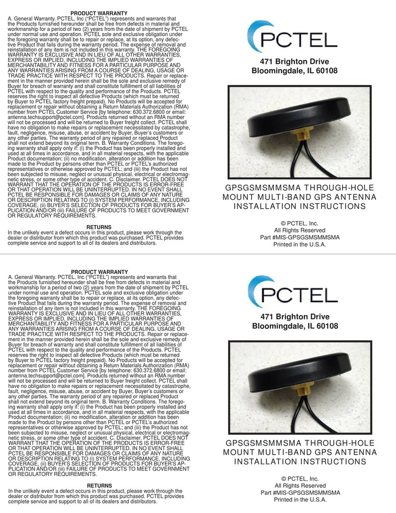
PCTEL GPSGSMSMMSMA User manual
PCTEL
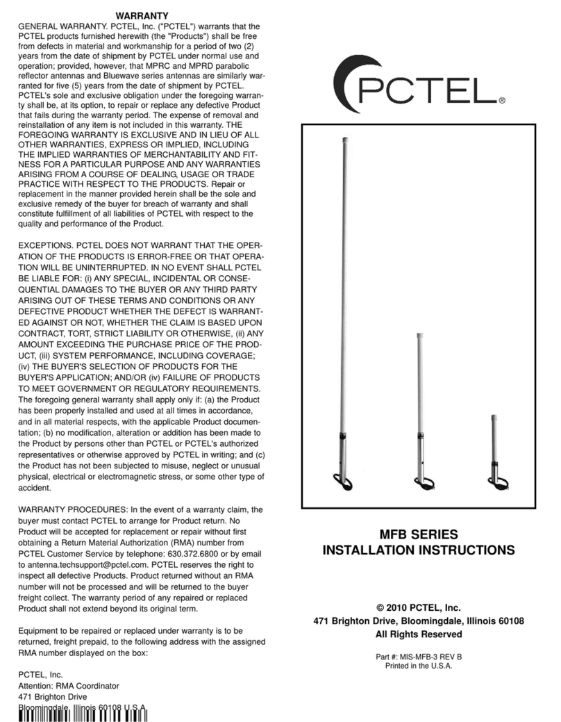
PCTEL MFB1443 User manual
PCTEL
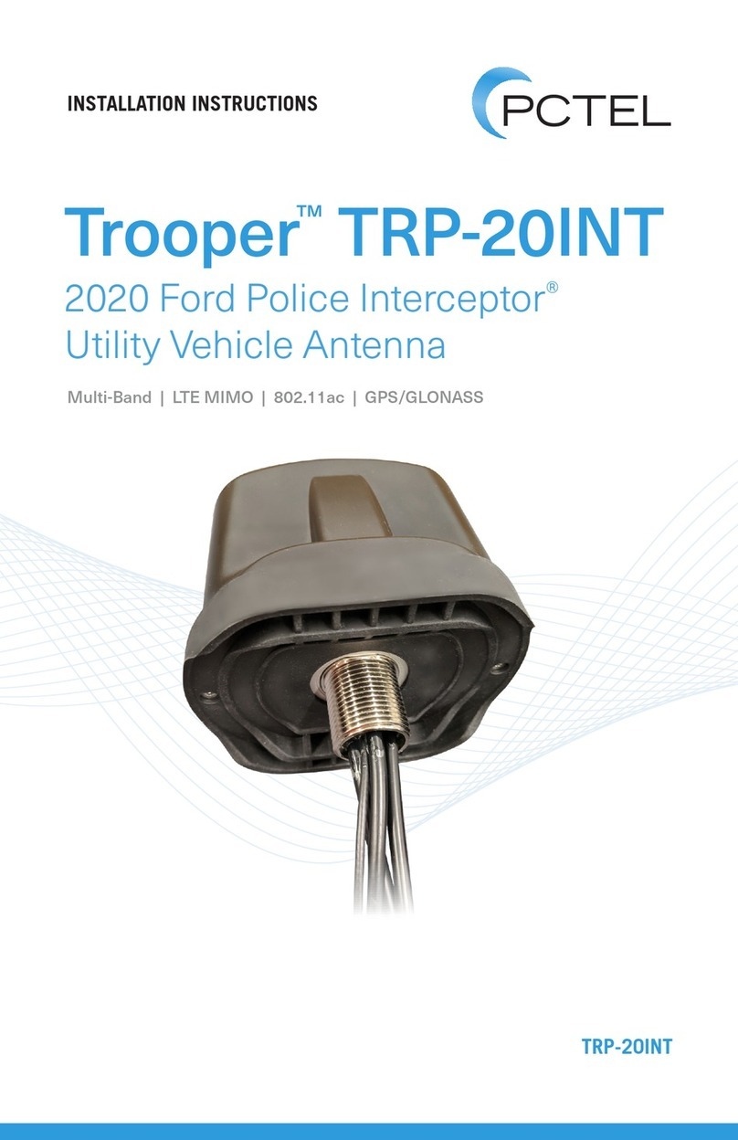
PCTEL Trooper TRP-20INT User manual
PCTEL
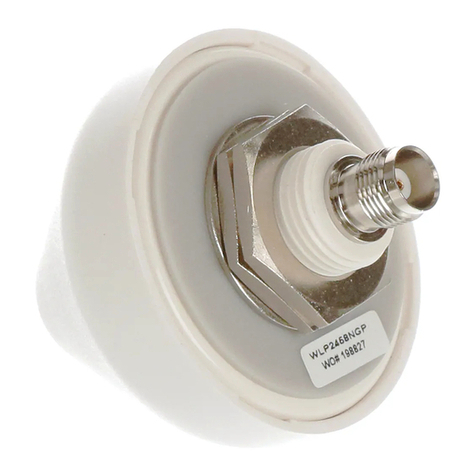
PCTEL WLP2458NGP User manual
Popular Antenna manuals by other brands
Barrett
Barrett 2018 OPERATING AND INSTALLATION Manual
CUSHCRAFT
CUSHCRAFT 20-3CD Skywalker Assembly and installation

Sennheiser
Sennheiser A 6 Instructions for use
TRENDnet
TRENDnet TEW-IA06D Specifications

KING
KING ONEPRO KOP4800 owner's manual
Dormakaba
Dormakaba BEST BACKSIDE ANTENNA KIT installation instructions
