PDi PowerWave 2 Busway Manual instruction

PowerWave 2TM Bus System
250-800A
Branch Circuit Monitoring System
Setup and Operation
Ctrl Nr: PM375107
Revision: 002

PowerWave 2 Bus System BCMS Setup and Operation
Cntl Nr: PM375107-002 2
Thank you for your recent purchase of a PowerWave 2™ Bus System from Power Distribution, Inc. For
safety reasons as well as to ensure optimal performance of your PowerWave 2™ Bus System, please
carefully read the instructions before trying to install, operate, service, or maintain the system.
For any questions regarding the installation, operation, service, or maintenance of your PowerWave 2™
Bus System, please contact us:
Power Distribution, Inc. | 4200 Oakleys Court | Richmond, VA 23223
PowerWave 2™ Bus System
250–800A
Branch Circuit Monitoring System
Setup and Operation
Control Number: PM375107 Rev 002
© 2017 by Power Distribution, Inc. All rights reserved.
Release date: November 2017
PDI, JCOMM, Quad-Wye, ToughRail Technology, and WaveStar are registered trademarks of Power
Distribution Inc. All other trademarks are held by their respective owners.
Power Distribution, Inc. (PDI)
Power Distribution, Inc. (PDI) designs, manufactures, and services mission critical power distribution,
static switching, and power monitoring equipment for corporate data centers, alternative energy,
industrial and commercial customers around the world. For over 30 years, PDI has served the data center
and alternative energy markets providing flexible solutions with the widest range of products in the
industry.

Contents
Cntl Nr: PM375107-002 3
Contents
Safety ............................................................................................6
1BCMS Options........................................................................7
2Customer Network Connections ............................................9
2.1 Comm Box Customer Connections ....................................................... 9
2.2 Making a Modbus RTU Connection ....................................................... 9
2.3 Daisy-chaining Power Feeds ............................................................. 11
2.3.1 Daisy-chaining Power Feeds using Modbus RTU ........................ 11
2.3.2 Daisy-chaining Power Feeds using Modbus TCP/IP..................... 12
2.4 Tap Off Box Connections .................................................................. 12
3BCMS Setup: Accumulator Application.................................14
3.1 Download Setup Software and Other Documentation ........................... 14
3.2 Start the Accumulator Setup Application ............................................ 15
3.3 Accumulator Setup Application Tabs .................................................. 15
3.4 Setup Tab ...................................................................................... 16
3.4.1 Finding New Devices on the Bus Run ....................................... 18
3.4.2 Updating Setup Information ................................................... 18
3.5 Setup Tab: Identifying Devices on a Bus Run...................................... 18
3.5.1 Addressing on a Bus.............................................................. 18
3.5.2 Setup Device Designations ..................................................... 18
3.6 Setup Tab: Manipulating the Device List............................................. 19
3.6.1 Add, Remove, or Swap Devices .............................................. 19
3.6.2 Identify Tap Off Boxes with Blinking LED ................................. 20
3.7 Ibus Setup Tab: Global Settings for Tap Off Boxes .............................. 20
3.7.1 Set Electrical Characteristics for All Tap Off Boxes..................... 20
3.7.2 Calibrate Voltage for the Bus Run ........................................... 21
3.7.3 Current Settings ................................................................... 21
3.8 Data Tab ........................................................................................ 22
3.8.1 Set Unit Name ...................................................................... 24
3.8.2 Setting Point Values and Clearing Alarms ................................. 24
3.8.3 Option Registers ................................................................... 25
3.8.4 Interacting with EPROM ......................................................... 25
47-Inch Local Display............................................................26
4.1 Customer Connections ..................................................................... 27
4.1.1 Mounting and Opening Enclosure ............................................ 27
4.1.2 Customer Power Connections to Display Interface Board............ 28

PowerWave 2 Bus System BCMS Setup and Operation
Cntl Nr: PM375107-002 4
4.1.3 Modbus Network Connections ................................................. 28
4.1.4 Modbus TCP/IP Network Connection ........................................ 29
4.2 Home Screen .................................................................................. 30
4.3 7-in Local Display Setup................................................................... 30
4.3.1 Login................................................................................... 31
4.3.2 Setup Screen Buttons............................................................ 31
4.3.3 Setting Parameters for Upstream Modbus TCP/IP ...................... 32
4.4 Modbus Addresses with Local Display................................................. 33
4.5 Operational Use of the Local Display .................................................. 35
4.5.1 System View Screen.............................................................. 35
4.5.2 End Feed Information Screen ................................................. 35
4.5.3 Tap Off Box Information Screen.............................................. 37
4.6 Setting up System View ................................................................... 37
4.7 Device Configuration: Setting Up Device Screens ................................ 39
Bibliography ................................................................................41
Glossary ......................................................................................42

Contents
Cntl Nr: PM375107-002 5
Figures
Figure 1 Customer Network Connections on Comm Box ...................................................................................................... 9
Figure 2 Attach Modbus RTU Cable to Accumulator ............................................................................................................ 10
Figure 3 Daisy-chaining Accumulators....................................................................................................................................... 12
Figure 4 Tap Off Box with Bus Rail Monitoring Connection ............................................................................................. 13
Figure 5 Quick Connect Tap Off Box Monitoring Cable ....................................................................................................... 13
Figure 6 Download Busway Customer CD ................................................................................................................................ 14
Figure 7 Start the Accumulator Setup Application................................................................................................................ 15
Figure 8 Accumulator Setup: Setup Tab..................................................................................................................................... 16
Figure 9 Setup Tab: Device Characteristics .............................................................................................................................. 17
Figure 10 Setup Tab: Modbus Parameters................................................................................................................................ 17
Figure 11 Setup Tab: Identify Tap Off Boxes with Blinking LEDs .................................................................................. 20
Figure 12 IBus Setup Tab.................................................................................................................................................................. 21
Figure 13 Setup: Data Tab Basic Operations............................................................................................................................ 23
Figure 14 Setup Data Tab: Enter Device or Unit Name ....................................................................................................... 24
Figure 15 Setup Data Tab: Selecting and Changing Specific Point Values .................................................................. 24
Figure 16 Setup Data Tab: Setting Option Register Values................................................................................................ 25
Figure 17 Setup Data Tab: Saving or Rejecting Point Changes ........................................................................................ 25
Figure 18 7-in Local Display with Six Bus Runs ..................................................................................................................... 26
Figure 19 7-in Local Display Enclosure Opened, Rear View ............................................................................................. 27
Figure 20 Customer Power Connections to Display Interface Board ........................................................................... 28
Figure 21 Customer Modbus Connections ................................................................................................................................ 29
Figure 22 Local Display Ethernet Connection for Modbus TCP/IP................................................................................ 29
Figure 23 Home, Setup, and System View Screens................................................................................................................ 30
Figure 24 Setup Screen...................................................................................................................................................................... 31
Figure 25 Login and Password Change ...................................................................................................................................... 31
Figure 26 Setup Options.................................................................................................................................................................... 32
Figure 27 System View Screen ....................................................................................................................................................... 35
Figure 28 End Feed Information Screen .................................................................................................................................... 36
Figure 29 Tap Off Box Information Screen ............................................................................................................................... 37
Figure 30 System View Screen with Corresponding Enable Screen.............................................................................. 38
Figure 31 End Feed Configuration Screen ................................................................................................................................ 39
Figure 32 Tap Off Box Configuration Screen............................................................................................................................ 40
Tables
Table 1 Modbus Settings ................................................................................................................................................................... 33
Table 2 Modbus Addresses When Using the 7-In Local Display ..................................................................................... 34

PowerWave 2 Bus System BCMS Setup and Operation
6
Safety
Please pay special attention to the use of “Danger” symbols throughout this manual indicating electrical
or other safety hazards. Following these safety instructions is extremely important to avoid possible
injury or death.
DANGER!
This symbol is used throughout this manual to indicate the presence of high voltages,
representing a hazard for electric shock, burn or explosion. Follow the instructions
carefully to avoid serious or fatal injury.
Follow safe electrical work practices:
•Read, understand, and follow the instructions before installing this product.
•Disconnect and lock-out all power supplying equipment before working on or installing
PowerWave 2 Bus System components, including the Branch Circuit Monitoring System.
Use a properly rated voltage sensing device to confirm power is OFF. However, Tap Off
Boxes can be inserted into an operational Bus System, if the Bus System has been tested and
certified.
•Install equipment in an appropriate electrical environment per local regulations.
•PCBs are ESD sensitive equipment. Ground yourself, discharge any static charge and ensure
that the device is effectively grounded before handling the unit.
Electrical equipment should be installed, operated, serviced, and maintained only by qualified personnel
and in accordance with all local safety codes. Power Distribution, Inc. assumes no responsibility for any
consequences arising out of the use of this manual. This document should not be viewed as sufficient
by otherwise non-qualified personnel to operate, service, or maintain the equipment discussed.

BCMS Options
Cntl Nr: PM375107-002 7
1BCMS Options
PowerWave 2™ Bus Systems can be deployed with optional power monitoring using PDI’s Branch Circuit
Monitoring System (BCMS). PowerWave 2 Bus Systems integrate power distribution and monitoring into
the same bus run. There is no need for a parallel facility to support monitoring and monitoring
communications. BCMS on PowerWave 2 Bus Systems is part of a family of PDI BCMS products.
PowerWave 2 BCMS can integrate with a WaveStar® BCMS Hub or the site Building Management System
(BMS) in the same way as BCMS on other PDI products.
There are several options for monitoring power:
•Input power source: BCMS Plus provides current and voltage monitoring at the power feed
(Standard End Feed or Center Feed)
•Tap Off Boxes: BCMS Plus provides current and voltage monitoring at each Tap Off Box circuit
oMonitoring is individually selectable by Tap Off Box
oIf any Tap Off Box has BCMS Plus, a communications cable is installed throughout the
bus run.
•Up to (32) devices can be monitored on a single bus run:
•(1) input power source and up to (31) Tap Off Boxes, or,
•No input power source and up to (32) Tap Off Boxes.
There are also several presentation options:
•Choice of any one of three upstream protocols (mutually exclusive options):
oModbus RTU (standard) at 9600 or 19200 bps, 4-wire or 2-wire
oModbus TCP/IP with a front-end protocol converter
oSimple Network Management Protocol (SNMP) with a front-end protocol converter
oNote: The protocol converters for Modbus TCP/IP and SNMP are different units. Only
one protocol converter can be installed.
•Modbus communication to an upstream Modbus master device includes these upstream devices:
oBuilding Management System (BMS) or Data Center Infrastructure Management (DCIM)
system.
oWaveStar® BCMS Hub, which can display information from many PowerWave 2 Bus
Systems and other PDI products.
▪Modbus RTU or Modbus TCP/IP is required upstream from the power feed to
the BCMS Hub
▪Note: SNMP cannot be used as a protocol upstream from the power feed to the
BCMS Hub.
▪The BCMS Hub can pass information through to another upstream Modbus
master such as a BMS or DCIM system.
▪Upstream Modbus TCP/IP from the BCMS Hub to another Modbus master is
available with an optional protocol converter.
oWaveStar® PowerWave 2 Bus System 7" Local Display, providing a local display hub for
Bus Systems:
▪Displays information for up to (6) bus runs with up to (1) power feed and up to
(15) Tap Off Boxes per bus run.
▪Modbus RTU is required upstream from the power feed to the 7" Local Display.
▪The Display can pass data through to another upstream Modbus master.

PowerWave 2 Bus System BCMS Setup and Operation
Cntl Nr: PM375107-002 8
▪An optional TCP/IP protocol converter can be installed on the upstream side of
the 7" Local Display.
▪Chapter 4 in this manual describes setup and operation for the 7" Local Display.

Customer Network Connections
Cntl Nr: PM375107-002 9
2Customer Network Connections
When you select any BCMS monitoring option, a Comm Box with monitoring PCBs is installed on the
power feed (Standard End Feed or Center Feed.). The Comm Box contains monitoring PCBs and may
contain an optional protocol converter (for either Modbus TCP/IP or SNMP upstream).
2.1 Comm Box Customer Connections
The following customer network connections are made to the Comm Box:
•(1) Modbus RTU cable entry hole. Installer runs the site network Modbus RTU cable through the
Modbus RTU hole and connects it to the Accumulator PCB in the Comm Box.
•(1) or (2) Ethernet ports (IN/OUT):
o(1) port if a protocol converter is installed for SNMP.
o(2) ports if a protocol converter is installed for Modbus TCP/IP.
•(1) USB port for connecting a PC to perform BCMS Setup.
With input power source monitoring, (3) fuses are also installed on the power feed to protect PCBs while
monitoring power input power phases (ABC).
Figure 1 Customer Network Connections on Comm Box
2.2 Making a Modbus RTU Connection
To present monitoring data to an upstream Modbus master, such as a BMS, BCMS Hub, or the 7-inch Local
Display, you must connect your upstream Modbus RTU cable directly to the Accumulator PCB. This is the
only network connection that requires you to open the Comm Box.
(2) Ethernet ports if Modbus
TCP/IP installed
(1) Ethernet port if SNMP
Protocol Converter installed
USB Port for
Setup from PC
Modbus RTU
Cable entry
hole
Fuses for
phase
connections
Standard End Feed with Comm Box
Comm Box

PowerWave 2 Bus System BCMS Setup and Operation
Cntl Nr: PM375107-002 10
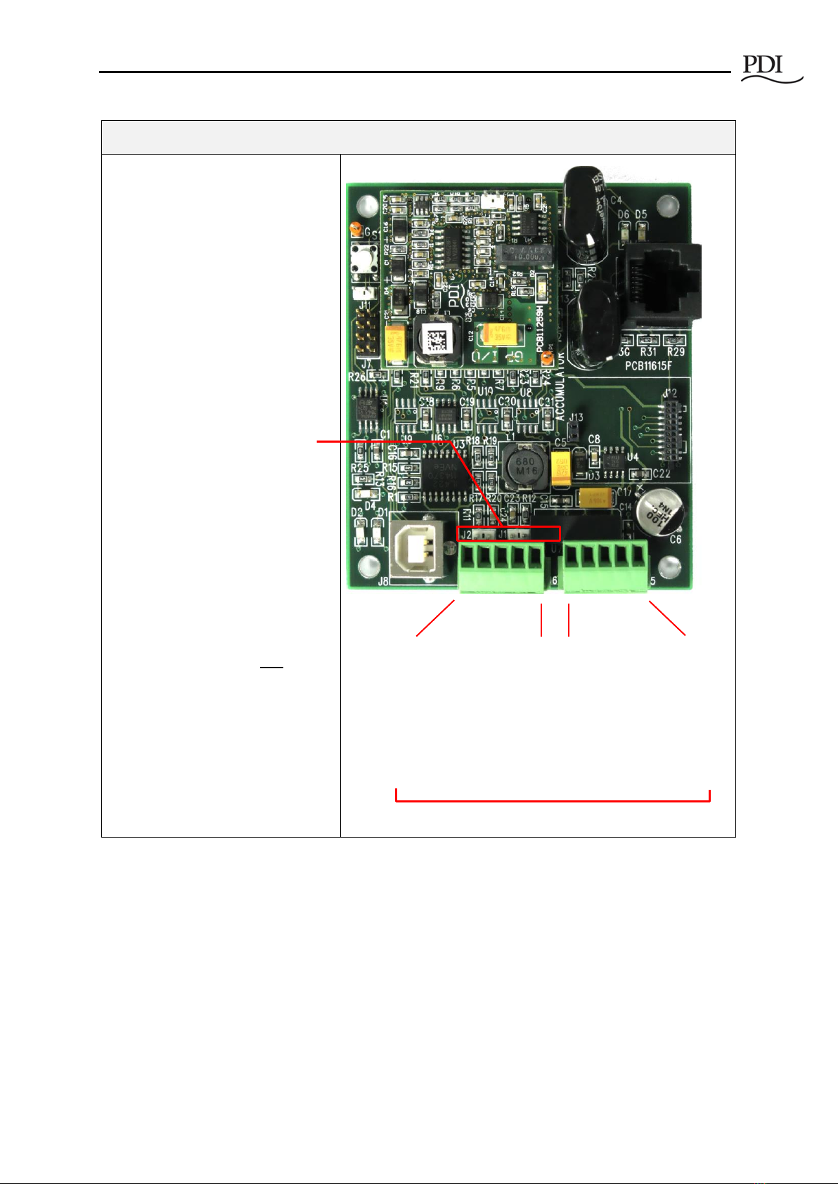
Figure 2 Attach Modbus RTU Cable to Accumulator
Attach Modbus RTU Cable to the Accumulator PCB in the Comm Box
1. Open the Comm Box door.
Unscrew the captive screws on
the Comm Box door and open
the door.
The door swings up to 180°.
2. Locate the Accumulator PCB in
the Comm Box.
The Accumulator PCB is in the
bottom right corner of the Comm
Box.
Note: If Modbus TCP/IP or SNMP
is a selected option, a protocol
converter is installed as shown.
When either option is selected,
you cannot connect a Modbus
RTU cable to the Accumulator
PCB because the protocol
converters and the Modbus RTU
cable use the same J5 connection
on the PCB.
3. Run your network Modbus RTU
cable through the Modbus RTU
cable entry hole on the bottom
of the Comm Box.
Accumulator PCB
Optional Protocol Converter for
Modbus TCP/IP or SNMP is installed here.
Customer Network Connections
Cntl Nr: PM375107-002 11
Attach Modbus RTU Cable to the Accumulator PCB in the Comm Box
4. Connect your Modbus RTU cable
to the Accumulator PCB at J5.
Accumulators can be daisy-
chained using J5-J6 connections.
(See Section 2.3.1, Daisy-
chaining Power Feeds using
Modbus RTU.)
5. Set 4-wire or 2-wire Modbus
RTU.
4-wire Modbus RTU is the
default configuration.
For 2-wire Modbus RTU install
jumpers on J1 and J2.
If Accumulator PCBs are daisy-
chained together, Modbus RTU
will be 2-wire if jumpers are
installed on J1-J2 on any
Accumulator PCB in the chain.
2.3 Daisy-chaining Power Feeds
It is often desirable to daisy-chain a cluster of nearby power feeds to consolidate data presentation onto a
single uplink. Power feeds can be daisy-chained using Modbus RTU or Modbus TCP/IP. All power feeds
must use the same upstream protocol. Power feeds cannot be daisy-chained using SNMP.
2.3.1 Daisy-chaining Power Feeds using Modbus RTU
When your upstream network link is Modbus RTU, power feeds are daisy-chained together by daisy-
chaining their Accumulator PCBs. Up to (32) Accumulator PCBs (or power feeds) can be daisy-chained
Accumulator PCB is shown here
rotated 180° from its orientation
in the Comm Box.
J6: G RX-RX+TX-TX+
J5
: G RX
-
RX
+
TX
-
TX
+
J6 is input from
another daisy-chained
Accumulator PCB.
J5 is output to a Modbus
master device, such as a
BMS or DCIM system or a 7"
Local Display, or to another
Accumulator PCB.
PowerWave 2 Bus System BCMS Setup and Operation
Cntl Nr: PM375107-002 12
together. However, the total number of devices in the chain—power feeds and Tap Off boxes—cannot
exceed the Modbus limit of 247 total devices.
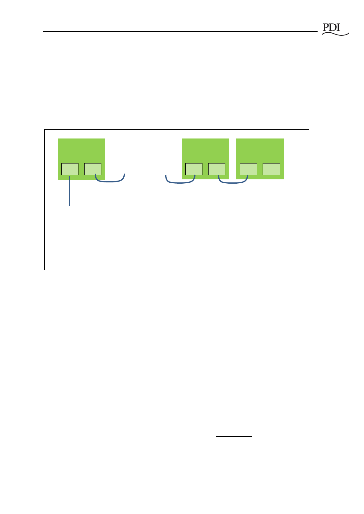
An Accumulator has two (2) RS 485 connectors for Modbus RTU device chaining (see Figure 2, Steps 4-5
and Figure 3). For chaining Accumulators:
•J5 is the upstream connection to the next Accumulator PCB or to the upstream Modbus master
device.
•J6 is the downstream connection to the previous PCB in the chain.
Figure 3 Daisy-chaining Accumulators
2.3.2 Daisy-chaining Power Feeds using Modbus TCP/IP
You can daisy-chain up to (32) power feeds with Modbus TCP/IP using the (2) Modbus TCP/IP Ethernet
ports on the Comm Box (see Figure 1).
2.4 Tap Off Box Connections
If you have selected Tap Off Box monitoring, then each Bus Rail, Elbow, and Tee in the bus run will have a
Communications Cable installed. The Communications Cable carries 24VDC and Modbus communication
for Tap Off Box BCMS (see Figure 4).
See PowerWave 2™ Bus System, 250A-800A, Installation and Operation, PM375106 for instructions on
inserting Tap Off Boxes into a Bus Rail. To connect the Tap Off Box to the Communications Cable, connect
the monitoring cable from the left side of the Tap Off Box to the Bus Rail (see Figure 4). The connection to
the Communications Cable is the same for all generations of Tap Off Boxes. However, the Quick Connect
Tap Off Box has a USB cable that must first be connected to an adapter (Figure 5).
IMPORTANT! Tap Off Boxes should be inserted in the bus run during setup to correctly identify
and address the units. Alternatively, you can install Tap Off Boxes, but delay connecting the Tap
Off Box Communications Cable to the Bus Rail until setup. See Chapter 3, “BCMS Setup: Accumulator
Application,”in this manual.
. . . .
J5
J6
Accumulator 32
J5
J6
Accumulator 1
J5
J6
Accumulator 2
To Modbus Master Device:
BMS, DCIM system,
WaveStar BCMS Hub, or
PowerWave 2 7-in Local Display
Up to (32) Accumulators (or power feeds)
can be chained together if the Modbus total
device limit (247) is not exceeded.
If the 7" Local Display is used, at most (6)
Accumulators (or power feeds) can be
chained together.
Customer Network Connections
Cntl Nr: PM375107-002 13
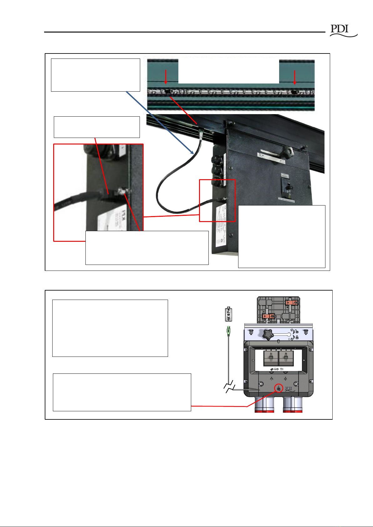
Figure 4 Tap Off Box with Bus Rail Monitoring Connection
Figure 5 Quick Connect Tap Off Box Monitoring Cable
Alarm Indicator Light
- Slow blink identifies Tap Off Box in setup
- Fast blink indicates alarm(s) present on Tap
Off Box
Modbus Communications Cable
connection from Bus Rail
After inserting a Tap Off Box into
the Bus Rail, connect the
monitoring cable from the Bus
Rail to the Tap Off Box.
Bus Rail has Modbus connections for
Tap Off Boxes every 13".
Tap Off Boxes with Universal U-
Channel and legacy Tap Off
Boxes connect to the
monitoring cable with the same
monitoring cable.
Legacy PowerWave Tap Off Box
is shown.
USB
Communications
Cable Adapter
Quick Connect Tap Off Box has a USB cable
for monitoring. Plug the USB connector into
a Communications Cable Adapter.
The USB cable with its adapter connects to
bus rail communications cable in the same
way as other Tap Off Boxes.
Maintenance Light:
- Slow blink identifies Tap Off Box in setup.
- Fast blink indicates fault loading firmware or bad
firmware image in Tap Off Box.
PowerWave 2 Bus System BCMS Setup and Operation
14
3BCMS Setup: Accumulator Application
The Accumulator Setup Application lets you identify, define, and calibrate monitored devices in a bus
run. A “device” is a monitored unit or connection that is represented by a points list. PowerWave 2
monitored devices are the following:
•The input power source at the power feed.
•Tap Off Boxes (each monitored Tap Off Box has its own points list).
3.1 Download Setup Software and Other Documentation
1. To do busway BCMS setup, you will need the following as prerequisites:
a. A PC with Microsoft Windows installed.
b. (1) Male A to Male B USB cable sufficient to reach from your PC to the Comm Box on the
Power Feed enclosure.
c. Setup software and USB device driver:
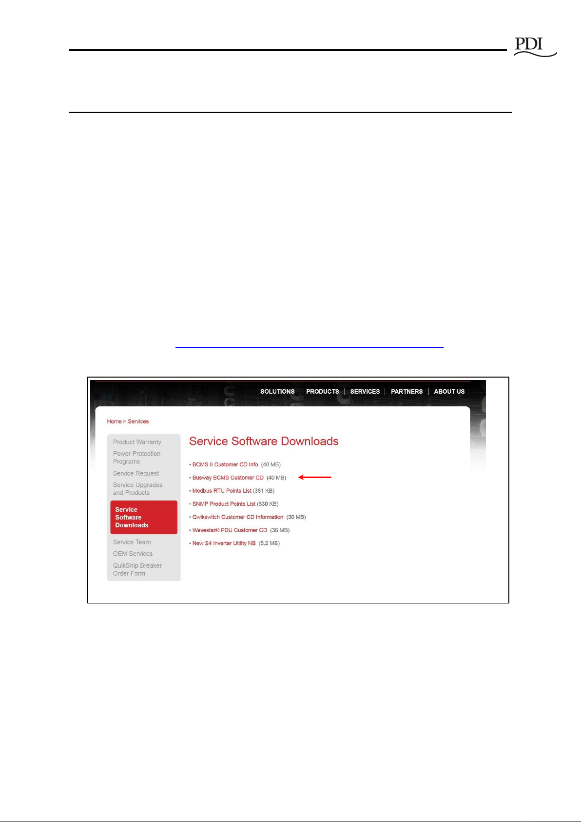
i. Download the software from the PDI website (or use the CD with your
shipment):
http://www.pdicorp.com/services/service-software-downloads
ii. Select Busway BCMS Customer CD.
Figure 6 Download Busway Customer CD
2. The Busway BCMS Customer CD is compressed. Extract the contents of the CD to its own directory.
The CD includes these files:
a. Setup application (Accumulator_Setup_Version)
b. Points Lists for input power source monitoring (IN PM) and Tap Off Box monitoring
(iBus)
c. Documentation

BCMS Setup: Accumulator Application
Cntl Nr: PM375107-002 15
3.2 Start the Accumulator Setup Application
1. Connect your USB cable to the USB connection on the Comm Box. If this is your first time using
Setup on this PC, wait for Windows to register the USB device.
Figure 7 Start the Accumulator Setup Application
2. Start the Accumulator_Setup (version).exe application (Figure 7) from the directory to which you
extracted the CD files.
a. A screen will appear on your PC like the screen in Figure 8 with the Setup tab selected.
All devices that the Accumulator has found in the bus run are listed on this screen with
the device count.
b. Possible errors:
i. If you get a DLL error, you may not have the Microsoft Dot.net core installed.
ii. If the message “Accumulator connected via USB” does not appear at the top of
the application page, you may not have the USB FTDI drivers installed and
recognized by Windows.
iii. If the message “No Accumulator found on USB” appears at the top of the page,
you may have disconnected the USB cable.
3.3 Accumulator Setup Application Tabs
The Accumulator Setup application has four tabs (Figure 7) that perform the following functions:
•Setup tab—set network addresses and parameters
oSet Modbus network parameters.
oManage Tap Off Box positions by address; add, remove, and rearrange Tap Off Boxes
along the bus run.
oAssociate devices (input power source and Tap Off Boxes) with Modbus addresses along
the bus run.
oReserve Modbus addresses for future Tap Off Box additions.
•iBus Setup tab—set parameters globally for all Tap Off Boxes on the bus run:
oSet voltage and current parameters for all Tap Off Boxes globally.
oCalibrate voltage for all Tap Off Boxes at once.
oClear alarms, min/max readings, and KWH for all Tap Off Boxes.
•Data tab—set Modbus register values for individual devices
oAssign name to device
PowerWave 2 Bus System BCMS Setup and Operation
Cntl Nr: PM375107-002 16
oSet Modbus register values
oClear individual alarm registers
•Window tab—for use by PDI engineering and service; not for customer use.
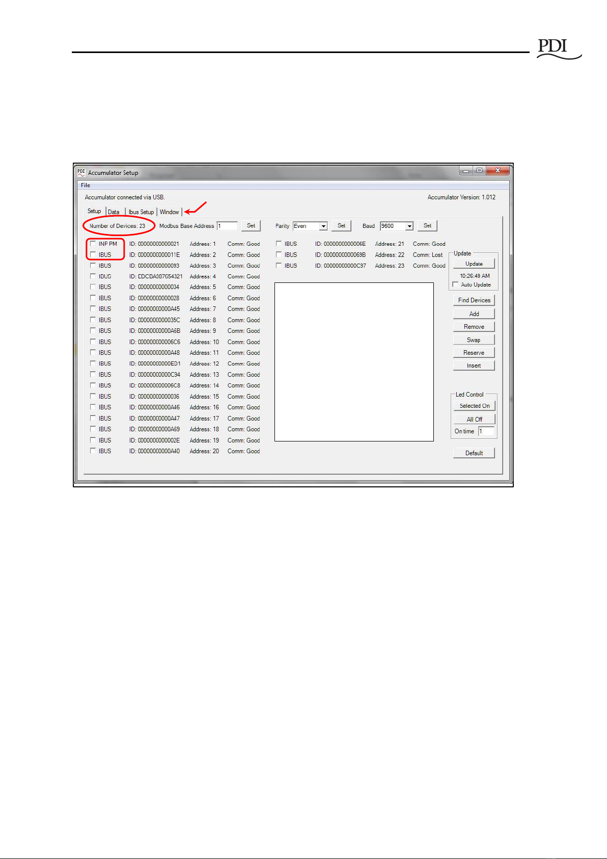
Figure 8 Accumulator Setup: Setup Tab
3.4 Setup Tab
The Setup Tab (Figure 8) lets you identify the monitored devices along the bus run, which are source
input power or Tap Off Boxes. Because devices are on a bus, devices are not identified by their order on
the bus.
1. Devices are listed by the PCBs that monitor power:
a) Input Power Source: INP PM = Input Power Monitor PCB. This PCB monitors the input power
source. There is only be one of these PCBs.
b) Tap Off Box: IBUS = iBus PCB. This PCB is in the Tap Off Box and monitors up to (6) poles.
c) The Number of Devices = INP PM + IBUS counts, or
= (0) input power source and ≤(32) Tap Off Boxes, or
= (1) input power source and ≤(31) Tap Off Boxes.
d) Note: If the bus run is monitored from the 7" Local Display, you are limited to (1) power feed and
up to (15) Tap Off Boxes in the bus run. The number of Tap Off Boxes is not increased if you do
not monitor the input power source.
Setup Tab lists all devices that the
Accumulator has found on the bus run.
A “device” is a logic unit associated with
a Points List. There are two device types:
INP PM (Input Power Monitor PCB):
monitors input power source at power
feed
IBUS (iBus PCB) in Tap Off Box:
monitors up to (6) poles in a Tap Off Box
(4) Setup tabs

BCMS Setup: Accumulator Application
Cntl Nr: PM375107-002 17
Warning: Connecting more than (32) devices for monitoring on a single bus
run may render the monitoring PCBs inoperable.
2. Devices are listed with these characteristics (Figure 9):
a) Device type (INP PM or IBUS)
b) ID = unique device ID (this is not the MAC ID), used to identify the device on the bus run
c) Modbus address
d) Comm: Good or Lost (showing whether the Accumulator can communicate with the device)
Figure 9 Setup Tab: Device Characteristics
3. Set Modbus parameters (Figure 10) for the bus run and the upstream network using boxes in the top
row of the Setup tab.
a) The Modbus Base Address is assigned to the first device in the device list. Other device addresses
increment up from this address.
b) Set network parity and baud rate using drop-down boxes or take defaults.
c) Addresses are fixed if the bus run is monitored by the PowerWave 2 Bus System 7" Local Display.
See the Setup Screen on the display for address requirements. See section 4.4 Modbus
Addresses with Local Display.
Figure 10 Setup Tab: Modbus Parameters
Device
Type
Unique
Device ID
Device Modbus
address
Unique physical device ID is
associated with Modbus address.
Comm: Lost indicates that the
Accumulator cannot
communicate with the device.
Modbus address of
first device in bus run
Network parameters

PowerWave 2 Bus System BCMS Setup and Operation
Cntl Nr: PM375107-002 18
3.4.1 Finding New Devices on the Bus Run
During setup, the Accumulator searches the bus for new physical devices every 30 seconds.
Click Find Device to force an immediate search for new devices. When you are adding Tap Off Boxes,
Find Device can save you a few seconds getting the device recognized by the Accumulator.
3.4.2 Updating Setup Information
Click Update to update all information including new devices and data from the points list for each
device.
Check Auto Update to have the Accumulator update data every (2) seconds.
Note: Turn off Auto Update if you are calibrating voltage or physically configuring the bus run. Auto
Update can clear or modify data you are entering.
3.5 Setup Tab: Identifying Devices on a Bus Run
3.5.1 Addressing on a Bus
As you add devices to the bus run, Setup assigns Modbus addresses sequentially starting at the specified
Modbus base address. The Accumulator can service up to (32) Modbus addresses on the bus run. For
example, if the Modbus base address is 64, devices are assigned addresses in sequence: 64, 65, 66, ..., up to
a maximum address of 95. There are no gaps in the address list.
The physical order of devices on a bus does not identify them:
•The communication connections along the Bus Rail simply provide a connection into the bus;
they are of no importance in assigning addresses.
•A device is identified by its ID and associated in Setup with a Modbus address.
•A Tap Off Box, once identified to the Accumulator by its ID, can be plugged into any bus rail
connector and will have the same Modbus address.
Note: If you are using the PowerWave 2 Bus System 7" Local Display, the Modbus addresses of your bus
runs have predetermined base addresses and address ranges. See section 4.4 Modbus Addresses with
Local Display.
3.5.2 Setup Device Designations
An Accumulator can monitor (32) Modbus addresses, and each address has one of four designations:
•INP PM (input power monitor PCB in end feed): There will be (1) INP PM per power feed, if
input power source monitoring is selected, or (1) per bus run.
•IBUS (iBus PCB in a Tap Off Box): There is (1) IBUS for each Tap Off Box that has BCMS
monitoring.
•Reserved. A Reserved device takes one of the (32) address positions in the Accumulator, even
though there is no physical device for this position.
•No Device. A Modbus address that has no associated physical device, is available for assignment,
and is not Reserved. When a new physical device (Tap Off Box) is installed, the first available No
Device address is assigned to it. (Note: This is a Modbus address, not a physical Modbus

BCMS Setup: Accumulator Application
Cntl Nr: PM375107-002 19
connection on the Bus Rail. A new Tap Off Box can be plugged into any available Modbus
connector and will be assigned the first available No Device Modbus address.)
To monitor (32) physical devices, you cannot have Reserved or No Device designations in the bus run,
once all devices are identified.
When you insert a new Tap Off Box into the bus rail, Setup replaces the first available (lowest address) No
Device position with an IBUS entry for the Tap Off Box. If a No Device address is not available, Setup
assigns the next sequential Modbus address at the end of the existing address list.
3.6 Setup Tab: Manipulating the Device List
Setup creates the initial device list from the devices it recognizes when it first starts up. Each device will
have a Modbus address associated with the ID of the device (assigned during manufacturing).
Recommendation: To better control assignment of Modbus addresses to Tap Off Boxes, do not connect
the Tap Off Box monitoring cable to the bus rail until you are ready to assign its address. This will allow
you to assign addresses one-by-one in sequence.
3.6.1 Add, Remove, or Swap Devices
Use the buttons on the right side of the Setup Tab screen to add, substitute, swap, or remove devices from
the Modbus address list.
“No Device” Entries
A No Device entry has a Modbus address, but has no physical device. A No Device entry can be replaced
by a new device, usually a Tap Off Box or iBus PCB.
•Insert Check a device box. Click Insert to add a No Device entry before the checked device. The
Modbus address of every device after the insertion point is incremented by 1.
•Remove Check the box for the device to be removed. Remove changes this address location to
No Device:
oReserved No Device
oIBUS No Device
oIN PM No Device
oNo Device Deleted Modbus address (Remove deletes the address only if No Device is
the last device in the list. Remove has no effect if No Device is not the last entry in the
address list.)
“Reserved” Entries
•Add Adds a new Reserved device at this address. This relative address in the device list will
unavailable for use until its status is changed to No Device.
•Reserve Check the box next to a No Device entry.
•Reserved addresses must be changed to No Device be available for assignment.
Swap Check two boxes in device list. Click Swap to swap the address of the two devices, and hence
change their positions in the list.
PowerWave 2 Bus System BCMS Setup and Operation
Cntl Nr: PM375107-002 20
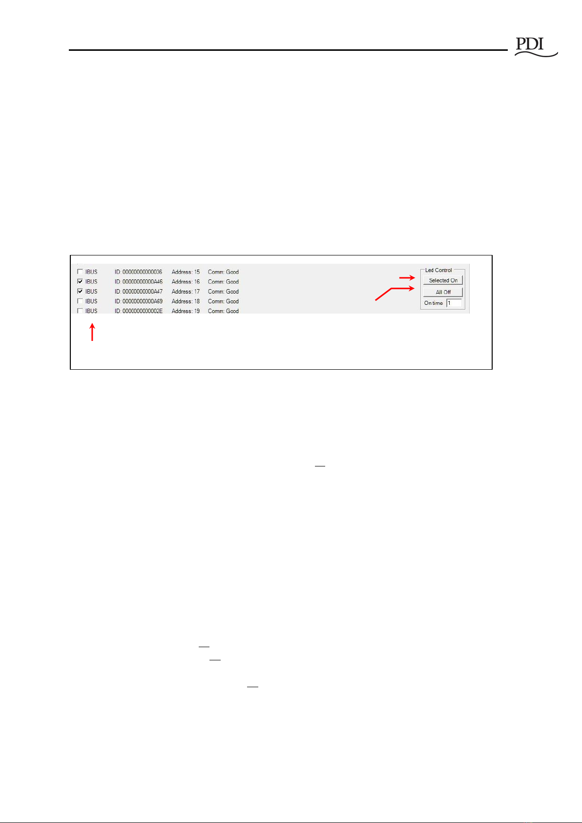
3.6.2 Identify Tap Off Boxes with Blinking LED
During Setup, to help you locate the Tap Off Box associated with an address, you can set the Alarm LED
blinking for up to (2) Tap Off Boxes. Check the box(es) for the specified IBUS unit(s) and click Selected
On in Led Control (Figure 11).
Typically, you will identify one unit only. But if you are swapping Tap Off Boxes, you may wish to select
(2) devices.
The Alarm LED (or Maintenance LED on Quick Connect Tap Off Box) on selected Tap Off Box(es) will blink
slowly. (When a Tap Off Box has an alarm, the LED blinks faster.) See Figures 4-5 for LED locations.
To stop the blinking, click All Off.
Figure 11 Setup Tab: Identify Tap Off Boxes with Blinking LEDs
3.7 Ibus Setup Tab: Global Settings for Tap Off Boxes
Use the Ibus Setup Tab to set electrical characteristics for all Tap Off Boxes in the bus run (Figure 12).
After setting global parameters, you can set parameters for individual Tap Off Boxes using the Data Tab
(see section 3.8 Data Tab).
3.7.1 Set Electrical Characteristics for All Tap Off Boxes
Set Voltage Type: Click the drop-down box to choose a standard AC voltage, such as 208, 400, or 575.
Voltage Settings automatically changes you check an option, for example, Voltage Enabled. Check these
boxes as appropriate:
•Voltage Enabled: Check box to have monitor voltage in addition to current on Tap Off Boxes.
•Frequency: Check 50Hz if 50 Hz frequency; leave the box unchecked if 60 Hz.
•Blink Led:
oCheck to turn on for all Tap Off Boxes (useful to check LEDs on all units).
oUncheck to turn off LED blinking for all Tap Off Boxes (useful to turn off previous
selections, making sure all LEDs are off).
•Un-check Blink Led to make turn off blinking on all Tap Off Box LEDs. This essentially resets the
LEDs on all Tap Off Boxes. Turn Blink Led on to test the LEDs.
Next to Voltage Type is Set Settings: Click Set Settings to accept the listed settings.
1. Select (1) or (2) IBUS
(Tap Off Boxes).
2. Select blink
interval in seconds
(On time).
3. Click “Selected On.”
4. When done, click “All
Off” to stop blinking.
Table of contents


