NSM ES 80 Series User manual

ALTERNATORI SERIE
ALTERNATORS TYPE
ALTERNATEURS SERIE
ACGENERATORS
ES 80
ISTRUZIONI D`USO
Lo scopo delle presenti istruzioni é indicare agli
utilizzatori le corrette condizioni d`impiego degli
alternatori NSM.
ATTENZIONE!
Le istruzioni fornite riportano informazioni atte ad
essere utilizzate da personale tecnico qualificato;
esse devono essere integrate dalle leggi ed dalle
norme vigenti.
Le macchine elettriche rotanti presentano parti pe-
ricolose in quanto poste sotto tensione ed in rota-
zione. Pertanto un uso improprio, la carenza di
manutenzione e lo scollegamento dei dispositivi di
protezione possono essere causa di gravi danni a
persone o cose.
VERIFICHE PRELIMINARI
Al momento della ricezione si raccomanda di
esaminare l`alternatore per controllare che non
abbia subito danni durante il trasporto.
IMMAGAZZINAGGIO
Se l`alternatore non viene posto immediatamente
in servizio dovrà essere immagazzinato in luogo
coperto, pulito, eprivo d`umidità.
Prima della messa in servizio dopo lunghi periodi
di inattività é consigliabile verificare la resistenza
di isolamento di tutti gli avvolgimenti. Con mac-
china a temperatura ambiente si devono misurare
valori
maggiori di 2 MΩ. In caso contrario bisogna pro-
cedere all`essicazione in forno
(a circa 60º-80º C).
ACCOPPIAMENTO MECCANICO
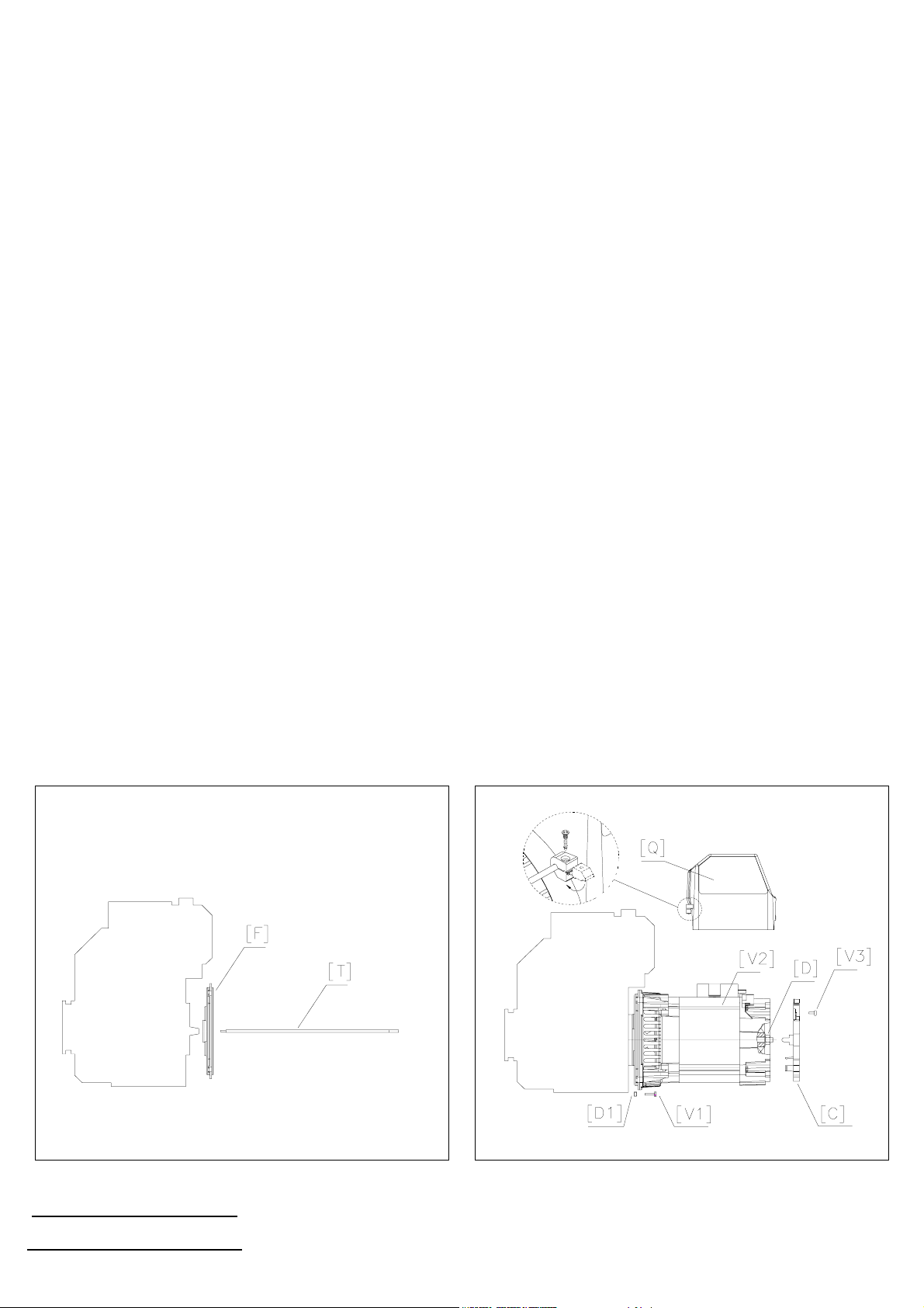
Si vedano le istruzioni per il montaggio a pag.4.
COLLEGAMENTO ELETTRICO
Verificare che i dati di targa siano conformi alle ca-
ratteristiche dell`impianto a cui l`alternatore é col-
legato. Eseguire i collegamento di pag.2. Provve-
dere anche al collegamento a terra dell`alternatore
utilizzando i morsetti predisposti.
Prima della messa in funzione é necessario verifi-
care la bontà di tutti i collegamenti e l`assenza di
impedimenti alla rotazione del rotore.
INSTALLAZIONE
Installare il gruppo in un locale ben ventilato. Fare
attenzione che le aperture di aspirazione ed
espulsione dell`aria di raffreddamento siano libere.
E' importante evitare che l`alternatore aspiri l`aria
calda espulsa dall`alternatore stesso e/o dal moto-
re primo nonchè i gas di scarico del motore.
MANUTENZIONE
L`alternatore e gli eventuali accessori devono es-
sere sempre tenuti puliti.
Verificare periodicamente che il gruppo funzioni
senza vibrazioni o rumori anomali e che il circuito
di ventilazione non sia ostruito.
INSTRUCTIONS
Object of these instructions is to give the user cor-
rect operating-conditions about NSM alternators.
ATTENTION!
The operating instructions include only the direc-
tions to be followed by the qualified personnel;
they must be supplemented by the relevant legal
provisions and standards.
Electric rotating machines have dangerous parts:
they have live and rotating components. There-
fore: improper use inadequate inspection and
maintenance and the removal of protective covers
and the disconnection of protection devices can
cause severe personal injury or property damage.
PRELIMINARY CHECKS
On receipt it is recommended to inspect the alter-
nator to find out whether it has got damages dur-
ing transportation.
STORAGE
If the alternator is not installed immediately, it
should be kept indoor, in a clean and dry place.
Before starting up the alternator after long periods
of inactivity or storage, the insulation resistance
winding is to be measured.
That should be higher than 2 MΩat room tem-
perature. If this value cannot be obtained it is nec-
essary to reset the insulation drying the winding
(using an oven at 60º-80º C).
MECHANICAL COUPLING
See assembling instructions at pag.4
ELECTRIC CONNECTION
As to the electric connection, the security ruling
standard are to be complied with. Check that data
on the plate are according to the circuit features,
to which the alternator is to be connected.
Connections to be made are in pag.2. Earthing the
alternator using the suitable terminals.
Before starting up it is advisable to check the
quality of all connections and there is not obstacle
to the rotation of the rotor.
INSTALLATION
Set up the unit in a well-cooled place.
Make sure that cooling air intake and discharge
openings are free and unblocked.
It is important the alternator doesn’t such the warm
air coming from the outlet of the alternator itself
or/and from the prime mover and motors gas.
MAINTENANCE
The alternator as well as the possible accessories
should always be kept clean.
It is recommended to periodically check whether
the set operates without anomalous vibrations or
noises, and the ventilation circuit is not obstructed.
MODE D`EMPLOI
L`objet des ces instructions est d`indiquer aux uti-
lisateurs les correctes conditions d`emploi concer-
nant NSM alternateurs.
ATTENTION!
Les instructions fournies contiennent des informa-
tions destinèes au personnel qualifiè; elles doivent
etre completèes par le dispositions de loi ou par
les Normes techniques en viguer.
Les machines electriques rotatives sont des ma-
chines prèsentant des parties dangereuses car
elles sont sous tension ou en mouvement. Par
consèquent: une utilisation anormale, la non in-
spection et le dèbranchement des disposititifs de
protection peuvent entrainer de graves dommages
pour les personnes ou les choses.
VERIFICATION PRELIMINAIRES
Aprés la réception on récommande d`examiner le
alternateur afin de vérifier qu`il n`a pas été en-
dommagé pendant le transport.
STOCKAGE
Au cas où l`alternateur ne doit pas être mis en
service immédiatament, il faut le stocker dans un
endroit couvert, propre et sec. Aprés de longues
périodes d`inactivité ou de stockage, on conseille
de measurer la résistance d`isolation de enroule-
ment qui devra être au dessue de 2 MΩ.
Si l`on ne peut pas obtenir cette valeur il est né-
cessaire de remettre l`isolation en état, en séchant
l`enroulement
(utilisant un four a 60º-80º C).
ACCOUPLEMENT MECANIQUE
Voyez l`operation de montage à la pag.4.
CONNEXION ELECTRIQUE
En ce qui concerne la connexion électrique, il vaut
bien respecter les dispositions de sécurité en vi-
gueúr, et s`assurer que les données nominales
soient en conformité aux circuit auquel
l`alternateur doit être connecté. Effectué le con-
nexions de la fig.4 à la pag.2 et la mise á la terre
de l`alternateur. Avant la mise en service il est né-
cessaire de contrôler le qualité des connexions et
qu`il n`existe aucun empechement a la rotation du
rotor.
INSTALLATION
Le groupe doit être installé dans un endroit bien
ventilé. S`assurer que les ouvertures de ventilation
ne sont pas obstruées. Éviter l`aspiration de l`air
chaude émise par l`alternateur lui-meme ou par le
moteur principal et du gaz d`èchappement du
moteur.
ENTRETIEN
L`alternateur et les éventuels accessoires doivent
être toujourus propres. Vérifier périodiquement
que le groupe fonctionne sans vibrations ou bruits
anomaux, et que le circuit de ventilation ne soit
pas obstruée.

Schema di collegamento - Wiring diagram - Schema des connexions
Anschlubschema - Esquema de conexiones
Resistenze avvolgimenti (20°C) e condensatori - Winding resistance (20°C) and capacitors
Resistances des bobinage (20°C) et condensateurs - Wicklungswiderstande (20°C) und kondensator
Resistencias de los bobinados (20°C) e condensador
STATORE AUS. CARICABATT. ROTORE STATORE AUS. CARICABATT. ROTORE
ST AT OR AUX. BAT T .CHARG. ROT OR ST AT OR AUX. BAT T .CHARG. ROT OR
kVA ESTATOR HILFSW. CHARGEBATT. kVA ESTATOR HILFSW. CHARGEBATT.
(*) BATT.LADER (**) BATT .LADER
ΩΩ Ω Ω
230V 240V ΩΩ Ω Ω
115V 120V
ES80 1000 1,0 6,50 19,3 0,21 3,97 7,5 8 1,3 1,20 12,5 0,19 3,97 7,5 8
ES80 A 1,5 3,63 8,85 0,18 4,85 13 14 2,2 0,66 6,35 0,15 4,85 13 14
ES80 B 2,2 2,18 7,75 0,14 5,60 13 14 3,0 0,38 5,52 0,12 5,60 13 14
ES80 C 2,7 1,57 5,10 0,12 6,30 18 20 3,4 0,28 3,10 0,11 6,30 18 20
(*) dual voltage version: Rblue-white = Rblack-brown = R/2 (**) dual voltage version: Rblue-white = Rblack-brown = 2R
50Hz - 3000rpm - 230÷240V 60Hz - 3600rpm - 115/120V
CONDENS .
CAP ACIT OR S
KONDENSATOR
µF (***) µF (***)
tipo
type
CONDENS .
CAP ACIT OR S
KONDENSATOR
MAX CORRENTEPER UNAPRESA
MAX CURRENT FROM ONE SOCKET
MAX COURANT POUR UNE PRISE
MAXIMALSTROM FUR EINEN STECKER
MAX CORRIENTE PARAUNATOMA
: 16A
(***): Valori indicativi: possono essere modificati in sede di collaudo. Indicative values: they can be changed during the test.
Valeurs indicatives: ils peuvent changer dans les essais. Ungefahre Angaben: Konnen bei der Abnahme abgeandert werden.
Valores indicativos: pueden ser modificados en el control final.

DIFETTO CAUSA - RIMEDIO DIFETTO CAUSA - RIMEDIO
Tensionecorretta
avuoto,
troppobassa
acarico.
Surriscaldamento
dellamacchina
Tensione
instabile
Macchinarumorosa
a)Diodorotantedifettoso:sostituirlo
b)Possibile sovraccarico: controllare la corrente di
carico
c)Ilmotorerallenta:contattareilcostruttoredelmotore;
possibilesceltaerratadelmotore
a)Aperturediventilazioneparzialmenteostruite:smon-
tare epulirelacuffiadiaspirazione eleaperturedi
espulsione ariadelloscudoanteriore
b)Possibile sovraccarico: controllare la corrente di
carico
a)Contattiincerti:controllareleconnessioni
b)Irregolaritádirotazione:verificarel'uniformitádiro-
tazione(contattareilcostruttoredelmotore).
a)Cuscinettiavariati:sostituirli
b)Accoppiamentodifettoso:verificareeriparare
a)Macchinasmagnetizzata:amacchinaavviataapplica-
reaimorsettid'uscitaperun secondounatensione
continuacompresatrai4.5e12V
b)Condensatore difettoso:sostituirlo
c)Diodorotantedifettoso:sostituirlo
d)Avvolgimentoin ctoodifettodiisolamentooconnes-
sioni difettose. Controllare le resistenze degli
avvolgimenti(veditabella)el`isolamento
a)Velocitádelmotoretroppobassa:regolarelavelocitá
a3150rpm (50Hz) o 3750rpm (60Hz) a vuoto.
b)Diodorotantedifettoso:sostituirlo
c)Avvolgimentiincortocircuito:controllareleresistenze
degliavvolgimenti(veditabella)
a)Condensatoreerrato:sostituirlo
b)Velocitádelmotoretroppoalta:regolarelavelocitáa
3150rpm (50Hz) o 3750rpm (60Hz) a vuoto.
Thereisn't
no-loadvoltage
after thestart
Toolow
no-loadvoltage
Toohigh
noloadvoltage
a)Lossofresidualmagnetism:feedforone secondthe
outputterminalwithaDCvoltage(4.5V-12V)without
stoppingthemachine
b)Faultcapacitor:changeit
c)Rotordiodefailureorshortcircuit:changeit
d)Winding short circuit or insulation fault or loose
connections. Check the winding resistance ( as
table)andtheinsulation
a)Speedofengine toolow:setit to3150rpm(50Hz)or
3750rpm(60Hz)withnoload
b)Rotordiodefailureorshortcircuit:changeit
c)Shortcircuitinwinding:checkthe windingresistance
(as table)
a)Wrongcapacitor:changeit
b)Speedofenginetoohigh:setit to3150rpm(50Hz)or
3750rpm(60Hz)withno load
Correct
no-loadvoltage,
lowloadvoltage
Excessiveheat
(overheating)
Unstablevoltage
Noisygenerator
a)Rotordiodefailureorshortcircuit:changeit
b)Possibleoverload:checkvalueofload current
c)The engine speed falls off: contact the engine
specialist; toolowenginepower
a)Ventilationaperturepartiallyblocked:disassemble
and clean the inlet casing or front cover if is
necessary.
b)Possibleoverload:checkvalueofload current
a)Loosecontact:checkconnections
b)Uneven rotation:check foruniformrotationspeed
(contacttheenginespecialist)
a)Brokenbearing:replace
b)Poorcoupling:checkandrepair
DEFAUT CAUSES - QUOI FAIRE DEFAUT CAUSES - QUOI FAIRE
Absence
detension
avide
audemarrage
Tensionavidedu
générateurinferieur
au80% dela
nominale
Tensiondu
générateur
supérieurau
nominal
a)Perteduremanent:aveclamachinetournanteappliquer
aux bornes de sortie pour 1 sec une impulsion de
tensioncontinue(batterie4.5-12V)
b)Condensateurdéfectueux:lechanger
c)Dioderotorencourt-circuit:changerlediode
d)Bobinages en cto ou a la masse ou connection
désserrées: vérifier les résistances des bobinages
suivantletableauetl`isolementverslamasse
a)Vitessedumoteurtropfaible:augmenterlavitessede
rotationavidea3150rpm(50Hz)ou3750rpm(60Hz)
b)Dioderotorencourt-circuit:changerlediode
c)Bobinagesenctooualamasse vérifierlesresistances
desbobinagessuivantletableau
a)Condensateuracapacitétropimportante:lechanger
b)Vitessedumoteurtropéleveé:diminuer lavitessede
rotationavidea3150rpm(50Hz)ou3750rpm(60Hz)
Tension
correcteavide
mais tropbasse
encharge
Echauffement
excessif
delamachine
Tension
instable
Machinebruyante
a)Dioderotorencourt-circuit:changerlediode
b)Possibilitédesurcharge:controlerlecourantdesortie
c)Le moteur thermique ralentit trop avec le charge:
celásignifiequelemoteurn`estpassuffisamment
puissantouqu'ilestmalregulé:regarderetconta-
cteréventuelmentleconstructeurdumoteur
a)Orifices de ventilation partiellement bouchées:
démonteretnettoyer
b)Possibilitédesurcharge:controlerlecourantdesortie
a)Controler que toutes les connections sont bien
serrées
b)Irregularité de rotation du moteur: conctacter le
constructeurdumoteur
a)Roulementdéfectueux:changerleroulement
b)Accouplementdéfectueux:vérifier
FAULT CAUSES - REPAIR FAULT CAUSES - REPAIR
RICERCA GUASTI - TROUBLE SHOOTING - RECHERCHES DE PANNES
Mancatensione
inuscita
avuoto
allapartenza
Tensioneinuscita
avuotominore
dell'80%
delvalorenominale
Tensioneinuscita
avuoto
troppoalta

UFF.COMMERCIALE / SALES OFFICE: Via Gran Sasso d'Italia 35/B, 42100 REGGIO EMILIA - ITALY - Tel ++39 0522330311 Fax ++39 0522330392
S
EDE E STABILIMENTO / HEAD OFFICE
:
Via Brandellero 2, 36036 TORREBELVICINO (VI) - ITALY - Tel ++39 0445595888 Fax ++39 0445595800
NUOVA SACCARDO MOTORI s.r.l.
E-MAIL: nsmsrl@tin.it - WEB SITE: http://w w w.nsmgenerators.com
ISTRUZIONI PER IL
MONTAGGIO
FORMA B3/B9 MONOSUPPORTO
ATTENZIONE: prima del montaggio
verificare che le sedi coniche di accoppia-
mento (sia dell'alternatore che del motore)
siano regolari e ben pulite.
1) Fissare la flangia [ F ] al motore (fig. 1).
2) Applicare il tirante [ T ] per il fissaggio
assiale del rotore avvitandolo a fondo sulla
sporgenza dell'albero motore (fig. 1).
3) Fissare l'alternatore completo alla flangia
con le 4 viti [ V1 ] inserendo nelle apposite
sedi i dadi [ D1 ] (fig. 2).
4) Bloccare assialmente il rotoreapplicando
e serrando il dado "serpress" [ D ] sul tirante
con chiave dinamometrica (coppia di serrag-
gio 25÷30 Nm). (fig. 2)
Attenzione: prima di applicare il dado osser-
vare che la porzione filettata del tirante entri
nel rotore permettendo cosí un sicuro bloc-
caggio.
5)Posizionare la cuffia di aspirazione aria
[ C ] nella sua sede (fig. 2)
6) Effettuare i collegamenti sul quadro elet-
trico [ Q ] e posizionarlo sulla carcassa,
fissandolo alle due viti [ V2 ] superiori con le
apposite due viti automaschianti (vedi parti-
colare in fig. 2)
7) Fissare quadro elettrico e cuffia di aspira-
zione aria con le due viti automaschianti [ V3 ]
(fig. 2)
ASSEMBLING
INSTRUCTIONS
B3/B9 FORM SINGLE-BEARING
CAUTION: before assembling verify that the
conical coupling parts are in order and clean.
1) Clamp the flange [ F ] on the drive motor
(fig. 1).
2) Apply the rod [ T ] for the axial clamping
of the rotor, and screw it tight on the engine
shaft (fig. 1).
3) Secure the complete alternator to its
flange using the 4 screws[ V1 ] inserting in to
theappropriate housingthe nuts [D1 ](fig.2).
4) Lock axially the rotor by placing and tight
the "serpress" nut [ D ] on the rod , using a
torque spanner (driving torque 25÷30 Nm).
(fig. 2)
Caution: before applying the nut, make sure
that the threaded part of the rod enters the
rotor in order to obtain a tight lock.
5)Place the rear inlet grill [ C ] in proper own
seat (fig. 2)
6) Make electric connections on the electric
board [ Q ] and place it on the frame, fixing it
to the two upper screws [ V2 ] with the
appropriate two self-threading screws. (look
at particular in fig. 2)
7) Fix electric board and rear inlet grill with
the two self-threading screws [ V3 ]
(fig. 2)
OPERATION
DE MONTAGE
FORME B3/B9 MONOPALIER
ATTENTION: Avant le montage verifier que
les siéges coniques pour l`accouplement (de
l`alternateur et du moteur) soient en ordre et
propres.
1) Fixer le flasque [ F ] sur ler moteur
thermique (fig. 1).
2) Monter la tige centrale [ T ] pour la fixation
axiale,la vissant afond surle boutd`arbre du
moteur (fig. 1).
3) Fixer l`alternateur complet a son flasque
avec les 4 vis [ V1 ] en inserant les écrous
[ D1 ] dans les sieges appropieés (fig. 2).
4) Bloquer axialementle rotor, enutilisant et
vissant a fond l`écrou "serpress" [ D ] sur la
tige centrale en utilisant la clef dynamometri-
que(couple de serrage de25÷30 Nm). (fig. 2)
Attention: avant de mettre l`écrou, controler
que la partie fileteé de la tige centrale entre
dans le rotor, permettant ainsi un bloquage
fermé.
5)Disposer le couvercle d`aspiration [ C ]
dans la propre siège (fig. 2)
6) Effectuer les connexions sur le tableau
electrique [ Q ] et le disposer sur la carcasse;
fixerlesurledeuxvis[V2]superieur avecles
deux vis de fixation autotaraudeuses (voir le
detail dans fig. 2).
7) Fixer le tableau electrique et le couvercle
d`aspiration avec les deux vis de fixation
autotaraudeuses [ V3 ]. (fig. 2)
FIG.1 FIG.2
This manual suits for next models
4
Other NSM Industrial Equipment manuals
Popular Industrial Equipment manuals by other brands

Centa
Centa CENTAX-G Assembly and operating instructions

Schmalz
Schmalz FXP operating instructions

Digital Control
Digital Control TERATRAK R1 user manual

Frontier
Frontier SA20F Owner's/operator's manual

Wilo
Wilo Wilo-Flumen EXCEL-TRE 20 Installation and operating instructions

Afag
Afag PDZ-128 Assembly and operating instructions

Parker
Parker mPR Series User's information guide

TECO
TECO MOTOVARIO PBH Series Instructions for installation, use and maintenance

SCHUNK
SCHUNK PGH Series Assembly and operating manual

Graco
Graco Series A Instructions-parts list

Bend-Tech
Bend-Tech Dragon mAchines troubleshooting guide

Bradley
Bradley S19-324D2 installation manual