Overview AXR Hardware Manual
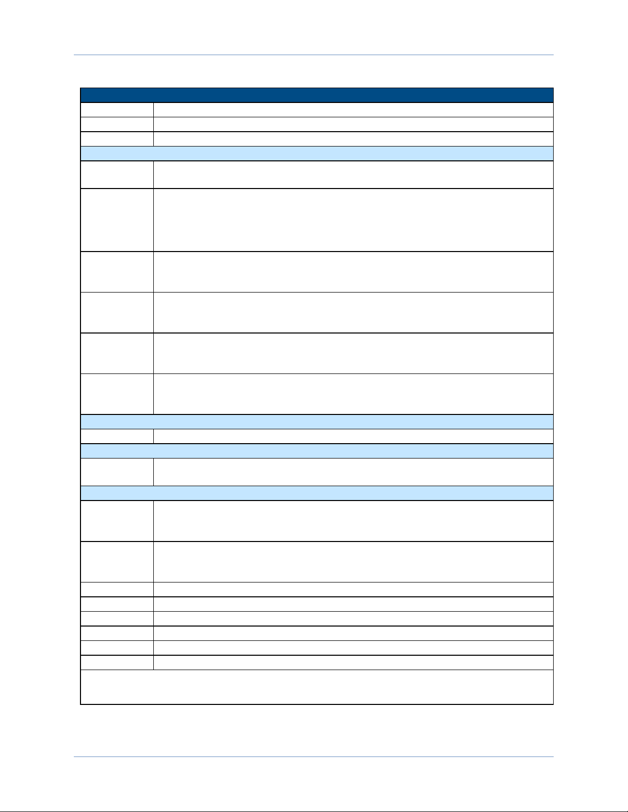
Table 1-1: Model Numbering System
AXRSeries Rotary Assembly
-100D Direct-drive tilt (A) axis and yaw (B) axis rated for 15 kg maximum load
-150D Direct-drive tilt (A) axis and yaw (B) axis rated for 30 kg maximum load
-150G Gear-drive tilt (A) axis with direct-drive yaw (B) axis; rated for 30 kg maximum load
Yaw Axis Configuration
-0 Yaw (B) axis tabletop height of AXR100D and AXR150x located at the center of rotation
of the tilt (A) axis; no counterweight attachment supported
-0E
Yaw (B) axis tabletop height of AXR100D and AXR150D located at the center of rotation
of the tilt (A) axis; includes attachment features for counterweights to balance offset
loads
NOTE:0E option not available on gear-driven AXRs (150G). Gearbox has sufficient holding torque to balance
maximum moment load.
-100
Yaw (B) axis tabletop height for AXR100D is located 100 mm above the center of rotation
of the tilt (A) axis; includes attachment features for counterweights to balance offset
loads
-100C
Yaw (B) axis with 3-jaw 3.25-inch (82.6 mm) diameter manual scroll chuck; chuck jaws of
AXR100D are located 100 mm above the center of rotation of the tilt (A) axis; includes
attachment features for counterweights to balance offset loads and 3-jaw manual chuck
-125
Yaw (B) axis tabletop height for AXR150x is located 125 mm above the center of rotation
of the tilt (A) axis; includes attachment features for counterweights to balance offset
loads
-125C
Yaw (B) axis with 3-jaw 5-inch (127 mm) diameter manual scroll chuck; chuck jaws of
AXR150x are located 125 mm above the center of rotation of the tilt (A) axis; includes
attachment features for counterweights to balance offset loads and 3-jaw manual chuck
Brake Configuration (Optional)
-B Holding brake for tilt (A) axis; only available on 100D and 150D configurations
Sealing Configuration (Optional)
-S Seals on the tilt (A) and yaw (B) axes to prevent ingress of airborne particulates into the
stage; the seal does not protect the AXR system from contact with fluids
Counterweight Configuration(Optional)
-CW1
Counterweight kit for AXR100 (-100, -100C) for offset loads ranging from:
-100: 23.5 N·m to 338 N·m
-100c: 48 N·m to 242 N·m
-CW2
Counterweight kit for AXR100 (-100, -100C) for offset loads ranging from:
-100: 1.4 N·m to 48 N·m
-100c: 6 N·m to 36 N·m
-CW3 Counterweight kit for AXR100 (-100) for offset loads of 41.3 N·m
-CW4 Counterweight kit for AXR100 (-100C) for offset loads of 23.4 N·m
-CW5 Counterweight kit for AXR100 (-0E) for offset loads ranging from 10.8 N·m to 54.2 N·m
-CW6 Counterweight kit for AXR100 (-0E) for offset loads ranging from 31.1 N·m to 124.4 N·m
-CW7 Counterweight kit for AXR100 (-0E) for offset loads of 15.7 N·m
-CW8 Counterweight kit for AXR100 (-0E) for offset loads of 13.1 N·m
1. Offset loads include both the payload and stage unbalance.
2. A linear combination of counterweight kits can be employed to achieve balance. Refer to Section 0.0.1. determine if application
falls within balance limits.
10 Chapter 1 www.aerotech.com