Robland KM 775 User manual

i
INSTRUCTIONS MANUAL
EDGE BANDING MACHINE
OF HOT-MELT GLUE
Model: KM 775 - 785
Document: Rev.1

Instructions manual KM 775 - 785
ii

Instructions manual KM 775 - 785
iii
TECHNICAL SPECIFICATION:
THICKNESS BOARD
MÍN.
MAX
8 mm
60 mm
WIDE BOARD
MIN.
75 mm
LONGITUDE BOARD
MÍN.
120 mm
THICKNESS EDGING
MAX.
3 mm (* 5 mm Solid Wood OPTION)
DRAG CHAIN SPEED
2 speed
9-14 m/mi
ELECTRIC CONNECTION:
END TRIMMING STATION: V-7
MOTOR: 0.35 Kw
TRIMMING STATION: JC-5 BC-5
MOTOR: 2 x 0.35 Kw OPTIONAL (2 x 0.55 Kw)
RADIUS SCRAPE UNIT: RB-8
FLAT SCRAPE UNIT: RR-7 (OPTIONAL)
POLISHER STATION: PC-9
MOTOR: 2 x 0.09 Kw
DRAG UNIT:
GEAR MOTOR: 1.5 Kw
PREMILLING STATION:PF-12
MOTOR: 2 x 1.5 Kw

Instructions manual KM 775 - 785
iv

Instructions manual KM 775 - 785
v
CE Declaration of Conformity
EG Conformiteitsverklaring - EG Konformitätserklärung
EC Declaration of Conformity - Déclaration de Conformité CE
Geachte Klant - Sehr Geehrter Kunde - Dear Customer - Cher Client,
Wij, wir, we, nous
NV WERKHUIZEN LANDUYT
Kolvestraat 44
8000 BRUGGE - BELGIE
verklaren hierbij dat de bouwwijze van de machines - erklären dass die Bauart der
Maschines - herewith declare that the construction of the machines - certifions par la
présente que la fabrication des machines
ROBLAND
voldoen aan de volgende richtlijnen / folgende Bestimmungen entsprichen / comply with
the following relevant regulations / sont conformes aux Normes suivantes:
Machine Directive 2006/42/CE - 2006/95/EC Low Voltage CE Directive
EMC Directive 2004/108/CE - EN 12100- Part 1 and Part 2 / EN 60204 Part 1 / EN 861
Nr. Serie
KM 775 - 785 0101012012-2031122012
Brugge 15/03/2011 Yves Damman
Aftersales
tevens gemachtigd om technisch dossier samen te stellen
also authorized to establish the technical file
également authorisé d’établir le dossier technique
auch ermächtigt die technische Unterlagen zusammen zu stellen

Instructions manual KM 775 - 785
vi
1Introduction:........................................................................................................ 1
1.1 Purpose of the operating manual:.................................................................. 1
1.2 Presentation:.................................................................................................. 1
1.3 Reference standards:..................................................................................... 1
1.4 General warnings and recommendations:...................................................... 1
1.5 Technical specifications:................................................................................ 2
2MACHINE Installation: ........................................................................................ 3
2.1 General safety rules at the KM 775 edge banding machine installation:........ 3
2.2 Limits of use:.................................................................................................. 3
2.3 Machine movement and sitting: ..................................................................... 4
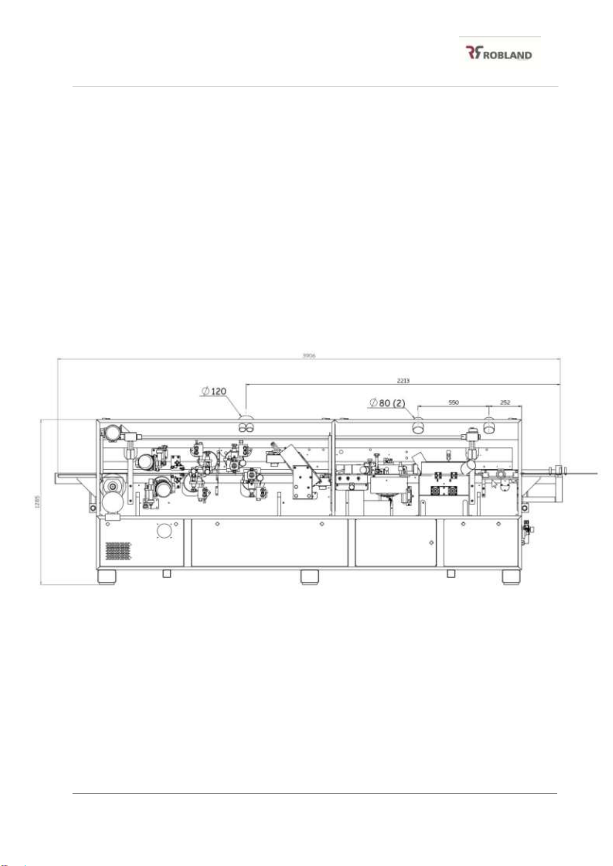
2.4 Dimensions and safety zones: ....................................................................... 5
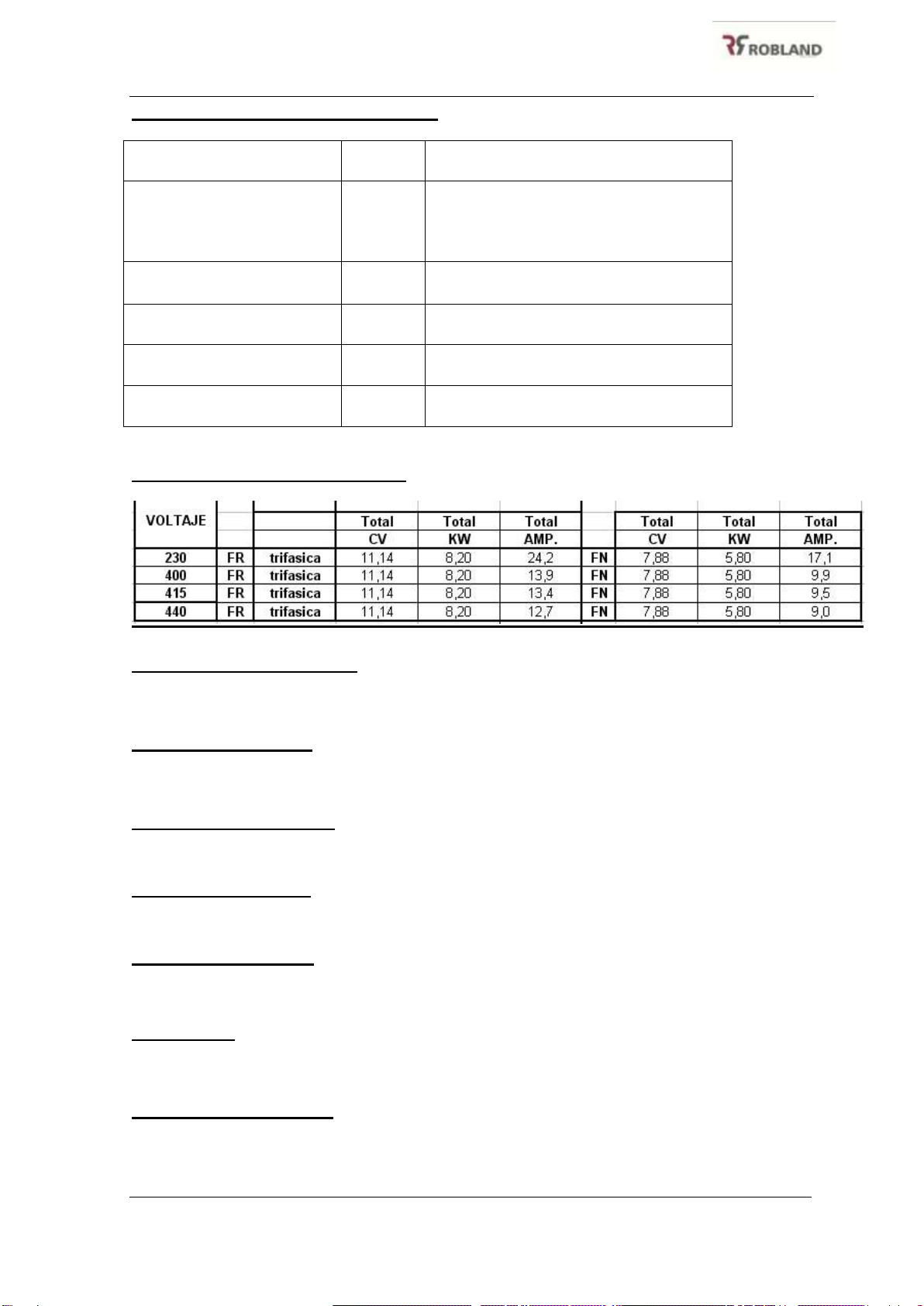
2.5 Electrical installation:...................................................................................... 5
2.6 Pneumatic installation:................................................................................... 7
2.7 Fitting the roll-holder tray: .............................................................................. 7
2.8 Fitting the apron:............................................................................................ 8
3Setting up and starting the machine:................................................................ 8
3.1 Control devices on the button panel:.............................................................. 8
3.2 Start-up and stop the machine....................................................................... 9
3.3 Adjusting presser height:................................................................................ 9
3.4 Loading and regulating the band in roll form:................................................. 9
3.5 Regulating surplus strip:............................................................................... 10
4Working stations:.............................................................................................. 11
4.1 PREMILLING STATION PF-12.................................................................... 11
4.1.1 Depth regulation of the pre-trimming:.................................................... 11
4.1.2 Adjusting the motor’s premilling: ........................................................... 11
4.1.3 Adjustment of the first motor:................................................................ 11
4.1.4 Adjustment of the second motor: .......................................................... 11
5Working stations:.............................................................................................. 12
5.1 Glue pot station:........................................................................................... 12
5.1.1 Dispensing glue: ................................................................................... 12
5.1.2 Glue level in the tank: ........................................................................... 12
5.1.3 Setting up for correct gluing:................................................................. 13
5.1.4 Replacing heating resistances:............................................................. 13
5.1.5 Security:................................................................................................ 15
5.2 Roller base:.................................................................................................. 15
5.2.1 Security:................................................................................................ 16
5.3 V-7 end trimming station:............................................................................. 16
5.3.1 Pneumatic regulation:........................................................................... 16
5.3.2 Security................................................................................................. 17
5.3.3 Safety systems:..................................................................................... 17
5.3.4 Working limits:....................................................................................... 18
5.3.5 Mechanical regulation:.......................................................................... 18
5.3.6 Replacing the end trimmer discs:.......................................................... 18
5.4 Trimming station JC-5:................................................................................. 19
5.4.1 Adjustment with flat cutters:.................................................................. 19

Instructions manual KM 775 - 785
vii
5.4.2 Replacing cutters:................................................................................. 19
4.5 Security......................................................................................................... 19
5.5 Radius Scraper station RB-8:....................................................................... 21
5.6 Flat Glue Scraper (Option)........................................................................... 23
5.6.1 Glue scraper adjustment....................................................................... 23
5.6.2 Regulation of the tracing tension........................................................... 23
5.6.3 Scraping depth regulation..................................................................... 23
5.6.4 Disengagement of the glue scraper unit ............................................... 23
5.7 Polisher station PC-9: .................................................................................. 25
6Maintenance:..................................................................................................... 26
6.1 Routine maintenance:.................................................................................. 26
6.2 Special maintenance:................................................................................... 26
7TROUBLESHOOTING:....................................................................................... 28
7.1 Machine does not start:................................................................................ 28
7.2 Irregular band feed:...................................................................................... 28
7.3 The end trimming station moves the piece when the board is passed
through it:................................................................................................................ 28
7.4 Router trimming diminishes:......................................................................... 29
7.5 The board moves:........................................................................................ 29
7.6 Uneven gluing:............................................................................................. 29
8INVERTER parameters...................................................................................... 29
9Pneumatic sketch.............................................................................................. 31
9.1 PNEUMATIC SCKETCH NOMENCLATURE............................................... 31
10 SPARE PARTS............................................................................................... 36
11 electric scheme.............................................................................................. 63

1
1 INTRODUCTION:
1.1 Purpose of the operating manual:
This manual is aimed at the operator and especially the personnel responsible for
using the machine correctly and thereby achieving good safety at work. It is, then,
recommended that the manual be read through carefully, paying particular attention to
the sections on warnings, precautions and methods of use, and that it is kept close to
hand for future reference, preferably next to the machine itself.
1.2 Presentation:
KM 775 edge banding machines are automatic machines equipped with a bottom
vertical gluing station, pressure rollers, front and back end trimming station, trimming
station, radius scraper, polisher and both top and bottom corner rounding station, as
well as a number of other features depending on version.
1.3 Reference standards:
KM 775 edge banding machines are designed and built in accordance with the
following standards:
Directive community: 2006/95/CE, 2004/108/CE, 2006/42/CE
Harmonized norms: EN 14121:2007, EN 60204-1:1999, EN 13849-1:2008, EN
953:1998, EN 1088:1996, EN 13850:2007
1.4 General warnings and recommendations:
Proper use of this machine involves perfect knowledge of these instructions for
use and of all the risks arising out of improper use. The machine must therefore only be
used by authorized personnel.
Safety when using this machine is only guaranteed for the functions and
materials specified in these instructions for use. ROBLAND accepts no responsibility in
cases where the machine has been used for purposes other than those indicated in and
complying with these instructions for use.
ROBLAND accepts no responsibility in matters related with machine safety,
reliability and performance in cases where the warnings and suggestions in this manual
have not been respected, in particular concerning the activities of erection and
assembly, use, routine and special maintenance and repair.
The electrical installation for the machine must comply with CEI 64.8 (CENELEC
HD 384-IEC 408) standards. The machine builder renounces all types of responsibility in

Instructions manual KM 775 - 785
2
cases where the machine has not been correctly connected to the earthed (grounded)
equipotential installation, such that the protective devices behind the machine itself are
not operative. For this reason, explicit reference is made to the entire contents of the
chapter relating to the characteristics of the electrical installation.
Original spare parts only must be used for special maintenance and repair work.
It is always advisable to contact our technical assistance service concerning
repairs. The responsibility for perfect machine operation rests solely with the user, if the
equipment has not been repaired or maintained by personnel authorized by ROBLAND.
1.5 Technical specifications:
Dimensions of machine:
Dimensions of the edge banding machine it is shown in a following shape:
(Measures mm) 3780 x 1400
(thickness of machine ivariable, depending on the position of the apron to a maximum of
2030 mm)
Weight machine: 1120 Kg.
Dimension cable: Electric cable 5x4.
Protection necessary for the installation of the machine:
Automatic diferencial swich pole 63 Amp. Sensibility 300 mA.
Pneumatic pressure of work / maxim: 6 - 8 Kg/cm2.Consumption 4 L/min
Diameter machine`s mouth aspiration (1) 120 mm and (2) 80 mm.
Air consumption Aspiration 800 m3/h. Speed min. 20 m/sec
Noise emitted by the machine. Empty 81 dB(A), full charge 84 dB (A).

Instructions manual KM 775 - 785
3
2 MACHINE INSTALLATION:
2.1 General safety rules at the KM 775 edge banding machine
installation:
The person in charge of the machine must be instructed in how to use the machine
correctly and informed of the relevant safety devices and tools and accessories.
The devices fitted to the edgebander must be correctly set up and adjusted.
The appropriate routine and special machine maintenance tasks must never be
neglected.
Before starting each job and before switching the machine on, check that the
control and working stations are free from chippings of previously removed
material.
The machine operator must always wear suitable safety clothing bearing in mind
the type of activity being carried out, protective gloves, safety footwear and
spectacles or goggles for example. Remember never to wear clothing or objects
that may get caught in the machine such as loose clothing, ties, watches, rings and
so on.
Before beginning any operation, check that there are no persons or other obstacles
in the vicinity of the machine that may present a risk.
Make sure the cable connecting the machine to the electrical supply is fully
unwound and not coiled up.
Do not situate inflammable substances near the machine to prevent the risk of an
accidental spark causing fire or explosion.
The machine operator must always consider the possible consequences before
moving his hands towards the most dangerous zones.
Never remove the yellow protections located on the gluing set, as they prevent the
risk of burns to the operator.
The operator must always be particularly careful when working the pedal that sets
the machine into operation.
Always keep the machine switched off when not in use.
Do not enter, touch or handle zones where movements take place before switching
the machine off.
2.2 Limits of use:
This machine has been designed to work with the following materials:
Solid wood
Laminated or unlaminated chipboard
M.D.F.
Various compound materials, provided they are wood-based
The machines have been designed and built to work in closed industrial
environments. Sitting the machine in an unsuitable location must be considered as
improper use. The machines are not intended for edge banding materials other than
those described, and any such use must also be considered as improper.

Instructions manual KM 775 - 785
4
To trim edges made of the following materials:
Laminated plastics
ABS
PVC
Melamine products
Wood band in roll form
Strip up to 3 mm thick
* For max edge thickness. 3 mm, thickness max. board 40 mm.
The command post of machine is easily accessible for workers, and is located
outside danger zone for them. From that zone and to be in position to operate the controls,
worker is the increased visibility of the machine, being away and protected from danger
zone. The staff required for the work of the machine will be as maximum of two operators.
One located at the entrance to introduce boards and other to collect boards mechanized.
The space required for these, is found in paragraph 2.4. The connection of the machine
should be carried out only by authorized personnel.
Before any handling in the machine and safety and proper functioning of the
machine, must be read with care this manual.
2.3 Machine movement and sitting:
The machine must be lifted and transported taking into consideration that the
support points must be as close as possible to the transporting bars. Take all possible
precautions in machine lifting, handling and moving operations to avoid the risks of
unforeseen movements which could endanger persons or property.
The machine must be sited on a flat surface able to withstand the weight of the
machine. Site it in an optimum position with regard to operational requirements, where
electrical connection is easy and with enough light to ensure that all parts of the
machine are visible. If the machine is unstable once in position, the support bolts should
be adjusted until the machine is stable and level.
Machine transporting
points

Instructions manual KM 775 - 785
5
2.4 Dimensions and safety zones:
The utmost care must be taken to avoid allowing objects that obstruct correct
working from occupying the safety zones as detailed in the figure below.
2.5 Electrical installation:
The electrical connection to the bottom right of the machine interior must be
opened to make ready the electrical installation. It is recommended that the machine is
not connected up the electricity supply until it is in its final position, and a check has
confirmed that the line voltage is the same as that shown on the machine nameplate at
the top of the main supply connection box. A check must also be made to confirm that
the main electrical supply to be connected to the machine complies with the following
safety requirements:
The installation must conform to IEC 408 standards.
Presence of earthed equipotential supply.
Presence of fuses or circuit-breakers to guard against short circuits on each
conducting cable, except the earth and neutral cables.
2.5 meters
2.5 meters
1.5 meters
2.5 meters

Instructions manual KM 775 - 785
6
To make the connection, insert the cables from the main supply in the four
terminals L1-L2-L3-N, securing them with the cable-press and fixing the earth cable
using the appropriate nut. Connection is via terminals, and the cable cross-section must
be at least 6 mm.
If the chain turns in the wrong direction, change two phases in the terminal
connection .
NAMEPLATE
MAIN-SWITCH PR-20
ELECTRICAL
CONECTION (INTERIOR)
RIGHT DOOR
CABLE-PRESS

Instructions manual KM 775 - 785
7
2.6 Pneumatic installation:
Connection to the line is made with a rubber or nylon tube of 6mm minimum
inside diameter, 10/12mm being ideal. Connect the air service (FRL) unit using a
minimum ¼” female fitting (supplied with the machine). Pressure must be at least 6
atmospheres, with a maximum of 7 atmospheres.
The air service unit consists of a Filter, to clean the air of dust and humidity
capable of damaging the valves and seals on the pneumatic cylinders; a pressure
Regulator to adjust the machine’s working pressure to its optimum value.
2.7 Fitting the roll-holder tray:
This accessory is supplied dismantled for transport purposes. Assembly consists
simply of fitting the crosspiece to the angle, then inserting the roll-holder disc, securing it
with the lever as shown in the figure.
Roller-holder disc
rollers
Roller-holder disk
brake
Centring rollers
Fixing screw
Disc height fixing
device
Angle

Instructions manual KM 775 - 785
8
2.8 Fitting the apron:
Insert the bars, fit the supports and finally fix the apron. Correct apron level is
1mm below the tops of the chain rollers, its function being to help to introduce the board.
If at a level higher than the chain, it would put a slope on the board and spoil the finish
on the final piece.
3 SETTING UP AND STARTING THE MACHINE:
3.1 Control devices on the button panel:
Emergency button
Main voltage pilot
ON / OFF button at touch screen. See specific instruction manual.
Apron
support bar
Fixing
screw
Apron
Fixing
screw
Apron
support

Instructions manual KM 775 - 785
9
3.2 Start-up and stop the machine
To start the machine, turn the main switch to ON. The general voltage pilot lamp
must be illuminated.
BEFORE CARRYING OUT ANY TASK AT OR AROUND THE MACHINE,
MAKE SURE IT IS COMPLETELY STOPPED, THAT IT CANNOT POSSIBLY MAKE
ANY MOVEMENT AND THAT THE MICROSWITCHES CANNOT BECOME ACTIVE:
DO THIS BY PRESSING ANY OF THE EMERGENCY STOPS.
Make sure there is enough glue in the container for the job to be done.
Operate the resistances On selector. (Q3)
Select the desired working stations.
Insert the strip as far as the first pressure roller.
Adjust the height of the presser to suit the panel to be passed through.
When the heating pot temperature reaches the set point figure, reset the machine
by deactivating the emergency stop, then pressing the green reset button. The
motors may now be switched on by pressing the motor On and chain activated
buttons.
The machine is totally stopped by opening the cabin, operating any of the
emergency stops or turning the main switch to OFF.
3.3 Adjusting presser height:
The height of the presser needs resetting every time the thickness of the board to
be edged changes. This simply involves loosening the levers on the presser fixing pads,
and using the lever to raise or lower the presser to the required value as indicated on
the numerical counter.
3.4 Loading and regulating the band in roll form:
To introduce the roll in the tray carries roll in having felt schedule, to go the first
song by the fixation roller, until it surpasses the center of pressure roller. To adjust the
Presser fixing
lever

Instructions manual KM 775 - 785
10
regulators of height of the song, leaving a small separation so that this it can move
easily. Set the pressure on the feed press using the pressure regulator located on the
door under the heating pot to a pressure of approximately 2,5 bar. To observe that so
much the faucet of the piston of ribbon feeding as that of the cutter is open. Finally to
adjust the pressure of the rollers of pressure by means of their regulators to the wanted
value, for further detail to look at "rollers base. To adjust the pressure of the cutter
according to the thick of the material 2-5 bar.
3.5 Regulating surplus strip:
AT THE FRONT: The amount of surplus may be adjusted via the feed time
regulator timer in the “CONTROL PANEL SCREEN”:
More time: more surplus at the front.
Less time: less surplus at the front.
AT THE BACK: This involves regulating micro S-13.
Moving the micro to the left increases the surplus at the back.
Moving the micro to the right decreases the surplus at the back.
Fixing
roller
Height
regulator
Feed
press

Instructions manual KM 775 - 785
11
4 WORKING STATIONS:
4.1 PREMILLING STATION PF-12
Composed by two high frequency motors (200 Hz, 12.000 RpM) of 1,5 Kw e/o. to
performance the pre-cleaning of the edge of the panel up to max. 3 mm of depth and 30
mm of height, before the gluing operation. To avoid chip, first motor turns in clock sense
and second against.
4.1.1 Depth regulation of the pre-trimming:
Adjust the readout onto the infeed fence. Be careful before to slack the fixing
pawls.
4.1.2 Adjusting the motor’s premilling:
Take care of one motor commands over the another one, in this case the first
one is the reference one and with the second one it should be taken the final trim, so it
is important the adjustment to follow up the first one.
4.1.3 Adjustment of the first motor:
With the readout at zero. Feed a panel till the working line of the motors.
Advance the motor till the cutting knives contact the panel edge. This means depth = 0.
Second step is to check that the measure of the readout is correct. In doing so, give i.e.
0,5 mm to the readout and check that after running a panel the measure trimmed is 0,5
mm.
4.1.4 Adjustment of the second motor:
As already indicated this second motors has to keep the reference of the first
one. Adjust it by means of the nylon pome till getting a continuous trim from the first one.
In case the perfect perpendicularity between drag chain and cutter is not
achieved, adjust the angle by means of the fixing screws.
Reado
ut
Fixing
pawls
Fixation screws
for the inclination
Bott of nylon for the
regulation of the depht
Fixation screws
First motor
Second motor

Instructions manual KM 775 - 785
12
5 WORKING STATIONS:
5.1 Glue pot station:
This consists of a roller to glue the band. It must trace 2mm on the board and with
no type of extra regulation must dispense the exact amount of glue on the different sizes
of board, in terms of both width and height.
5.1.1 Dispensing glue:
The thickness of glue on the dispensing roller is regulated by the regulator finger
on the glue flap.
TURNING CLOCKWISE REDUCES THE AMOUNT OF GLUE.
TURNING ANTI-CLOCKWISE INCREASES THE AMOUNT OF GLUE.
5.1.2 Glue level in the tank:
For correct operation, the level must not cover the access door to the inner tank,
because if this happens the gases produced will only be able to escape through the glue
nozzle, and this may cause irregularities in the amount of glue supplied to the edge. On
the other hand, with a very low level the glue would burn, losing its properties and even
forming a layer of encrusted glue that would insulate the glue from the heating
resistances in good conditions, leading to an increase in heating time.
Max. Glue level
Glue flap regulator
Clockwise supplies less glue
Anticlockwise supplies more glue
Securing nut
Thermostat probe casing

Instructions manual KM 775 - 785
13
5.1.3 Setting up for correct gluing:
If the glue is not evenly dispensed after adjusting and checking the points above,
for example if there are parts on the top without glue, the first thing to check is that the
panel is being cut square. Then check that the scoring disc has not made too great an
incision in the board. If neither of these is the problem, turn the glue pot fixing screws
and slope the station forwards if there is not enough glue on the top, and backwards if
there is not enough on the bottom. In other words, attempt to get the glue roller and
board parallel to each other.
The best way of doing this is first to take the distance between glue nozzle and
the wall of the presser, then to slightly loosen the glue pot fixing screws and slope the
station as necessary. Then retighten these four screws and measure the distance
between nozzle and presser again to check the inclination that the station has been
given.
5.1.4 Replacing heating resistances:
Once the tray has been withdrawn, to remove the pot first unplug and take out the
thermostat probe, then simply lift until it comes out from the pot swing pin.
GLUE POT M5: From outside it is easier to access the fixing cover for the bottom
and front heating resistances (Nº19,22). Having extracted these and the cable through
plate (nº42), there is full access to the resistances, which are protected by an asbestos
sheet (Nº20,23).
RESISTANCE Nº
RESISTANCE VALUE
32
600 W
33
500 W
34
250 W
Fixing
screw
This manual suits for next models
1
Table of contents
Other Robland Industrial Equipment manuals