PDK PDPG-H User manual

PDPG-H
PDPG-H
Dead-Weight Tester
User Manual

PDPG-H Manual
Page 2
Table of Contents
1 Introduction ......................................................................................................... 3
1.1 Product Overview ....................................................................................................... 3
1.2 Specifications ............................................................................................................ 3
1.3 Product Figures ........................................................................................................ 4
2 Installation & Operation ............................................................................ 6
2.1 Unpacking And Inspection .......................................................................................... 6
2.2 Product Requirement ................................................................................................ 7
2.3 Setup .......................................................................................................................... 8
2.4 General Operation ..................................................................................................... 9
2.5 Defined Pressure Calculations ................................................................................. 12
2.6 Storage ....................................................................................................................... 13
3 Troubleshooting ................................................................................................ 14
3.1 Overview .................................................................................................................... 14
3.2 PDPG Troubleshooting Checklist ............................................................................. 14

PDPG-H Manual
Page 3
Maximum Pressure
Oil - up to 200 MPa
Measurement uncertainty
0.008 % of reading
Piston cylinder material
Tungsten carbide
Mass material
Stainless Steel
Mass set
Oil - 50 kg set / up to 100 kg available
Test port
Oil - 9/16" UNF Cone & Thread (AE F250C, HIP HF4)
Weight
12 kg
Power Requirements
220 VAC, 50/60 Hz
Media
Hydraulic - Oil (Sebacate Oil recommended)
P/C and pressure range
Mass
Piston
Piston 0.1 kg
Piston+Bell 0.5 kg
50 kg
100 kg
0.2 MPa / kg
0.02 MPa
0.1 MPa
10 MPa
20 MPa
0.5 MPa / kg
0.05 MPa
0.25 MPa
25 MPa
50 MPa
1 MPa / kg
0.1 MPa
0.5 MPa
50 MPa
100 MPa
2 MPa / kg
0.2 MPa
1 MPa
100 MPa
200 MPa
1. Introduction
1.1 Product Overview
Dead-Weight Tester is used as a generator of an accurately known pressure. It
measures pressure as force per unit area. Therefore, Dead-Weight Tester is the most
accurate pressure calibrator.
M (Mass) x g (Acceleration Of Gravity)
P (Pressure) = -------------------------------------------------------------
Ae (Effective Area)
A typical PDPG Dead-Weight Tester system includes PDPG main platform body,
Piston-Cylinder Module, Mass and Pressure Controller that user can be selected
depending on user's system configuration.
1.2 Specifications

PDPG-H Manual
Page 4
1.3. Product Figures
1.3.1 Front Panel
Figure 1. Front Panel
1.3.2 Product Dimension
Figure 1 Front And Side Appearance & Dimension [W:39 cm, D:30 cm , H:33 cm]

PDPG-H Manual
Page 5
1.3.3 Appearance Of System
Figure 2. Appearance Of System
No.
Parts
No.
Parts
①
Piston - Cylinder Module
⑥
Height Adjustment Knob
②
Bell
⑦
Manual Piston Rotation button
③
Mass
⑧
Automatic Piston Rotation Button
④
Instrument Platform Handle
⑨
Piston Position Indicator
⑤
Platform
Table 1. Description of [Figure 2. Appearance Of System]

PDPG-H Manual
Page 6
2. Installation
2.1. Unpacking and Inspection
2.1.1 Unpacking
PDPG Dead-Weight Tester delivered via PDK or shipped and packed with wooden
case that included basic accessories.
2.1.2 Inspection
Checking all of the parts from PDPG system. Refer to Table2 when its unpacking.
PARTS
PART #
PDPG-H System
Included Accessaries:
Pressure Controller ( OPS - J )
1
Piston-Cylinder Module
1
Mass set
1
Mass Tray
1
Fitting and Adaptor Set
1
SUS Tube
1
Power Cable
1
Sebacate Oil ( 1 Liter )
1
User Manual
1
KOLAS Certificated Calibration Report
1
☞ Parts on above equipped directly to the product can be shipped.
Table 2 . P D P G P arts List

PDPG-H Manual
Page 7
2.2. Product Requirement
PDPG is composed of separate with pressure generator. To use the equipment, it
required to install a pressure controller. Basically PDPG system includes pressure
controller OPS-J.
Before PDPG system installing, the following points should be noted.
▶ The stability of the table :
PDPG weight is approximately 12 kg. 35 kg of Mass set can be raised. The table
should selected with no change horizontally when mass set raised to the maximum
weight.
▶ The location of the platform other than the equipment and components :
It required sufficient space to install the Multi-test port, pressure controller and etc.
External pressure connection tubing and fitting MUST use same as
PDPG maximum pressure or more.

PDPG-H Manual
Page 8
2.3. Install
2.3.1 Setup
▶ Front panel of PDPG and pressure controller facing you, it shall be placed on the
table.
▶ After placed PDPG system, using height adjustment knob and see the level for
adjusting horizontal.
▶ User can choose the placement of the platform and pressure controller. but here is
recommended placement is as follows.
ex) From left side
Mass Set → PDPG Platform → Pressure Controller → Multi-Test port
2.3.2 Pressure Tubing Connection
General information for connection
▶ Connect the PDPG platform with pressure controller that using PDK supplied
connection kit.
▶ Using tubing line(PDK Supplied) to connect rear test port of PDPG platform and
side port of pressure controller.

PDPG-H Manual
Page 9
2.4. General Operation
2.4.1. The selection of Piston-Cylinder module and Mass combination
PDPG be able to use many different ranges by replacing each range of Piston
Cylinder module.
▶ Piston Cylinder Module : 1 MPa/kg
▶ Composition Of Mass
1) Piston Cylinder : 1 bar
2) Bell : 4 bar
3) 1 bar
4) 2 bar - 1
5) 2 bar - 2
6) 5 bar
7) 10 bar
8) 20 bar - 1
9) 20 bar - 2
10) Make-Up 45 bar
11) 50 bar - 1
12) 50 bar - 2
13) 50 bar - 3
14) 50 bar - 4
15) 50 bar - 5
16) 50 bar - 6
17) 50 bar - 7
18) 50 bar - 8
19) 50 bar - 9
20) 50 bar - 10
21) 50 bar - 11
22) 50 bar - 12

PDPG-H Manual
Page 10
2.4.2. Purging Air
▶ Purging Air on Pressure Generator/Controller before connect PDPG base.
① Open the Vent Valve then operate lever type hand pump for 4 - 5 times.
② It can see the Air bubble on left hole in oil reserver during step ①.
③ After finished step ②, turn Volume Controller to end of CW direction then
operate lever type hand pump for 4 - 5 times to see bubble coming out.
④ If there is no bubble, turn back to CCW direction, do step ① again.
2.4.3 Calibration/Adjustment
Verified that the default setting of the PDPG system has been complete before started.
▶ Connect UUT(Unit Under Test) to Pressure generator or test port.
▶ Loading mass on mass loading bell as much as user wants to measure the
pressure.
① Close Vent Valve then using lever type hand pump to generate initial pressure
generating.
② After initial pressure generated using Volume Adjust to increasing the pressure
slowly. (Volume Adjust : CW - Pressurize, CCW - Reduce Pressure)
③ Pressurize with checking the Piston location during Step ②. measure when LED
indicates "Green color".
④ 9 of LED indicator located on front panel for measuring piston position.
Approximately 1 mm height difference on each LED.

PDPG-H Manual
Page 11
○ Red : Out of measuring area (Piston is fully floating or in the bottom)
○ Yellow : Instability area (Piston is a little float or down)
○ Green : Measurable area
⑤ In order to reduce the friction of the piston and the cylinder, rotate the piston.
1) Red Button Only :
When this button is pressed, motor works then piston rotates always. If
piston is fully float or in the bottom, piston does not rotate and motor rotates
only. Even piston is in out of measuring area, motor always works therefore
we recommend between measurable area.
2) Red+Green Button : When these buttons are pressed, motor works and
piston rotates when piston is in measurable area. Automatically stop the
piston and motor rotation when piston is in out of measuring area.

PDPG-H Manual
Page 12
gh
TTPA
Cmg
Paf
rcpno
m
a
)(
)])((1)[1(
cos1
rr
aal
gq
r
r
-+
-+++
+
÷
÷
ø
ö
ç
ç
è
æ-
=å
⑥ Record the reference pressure value and UUT pressure value.
- At this point reference pressure means pressure value that total mass loaded.
- After finished measuring, if next measuring point is UP(pressurized), make a
piston position a bit lower then stop the piston rotates, repeat step ②.
- If pressure is Down point, make a piston a bit higher then stop the piston
rotates, repeat step ②.
2.5. Reference Pressure Calculation
▶ Basic Calculation : Add Bell+Piston Cylinder's pressure value with loaded masses
that pressure value marked on masses.
Ex) Basically Bell + Piston : 5 bar
If masses are as following, 45 bar 1ea, 50 bar 3 ea
Total pressure value is 5+45+50+50+50 = 200 bar
▶ Precision Reference Pressure Calculation
m = T otal m asses load ed on p iston
g = Local g ravity
ρa = A ir density
ρm = M ass d ensity
γ= S urface tension coefficient of O il (D oes n ot applied p neum atic)
C = C ircum ference of piston (D oes n ot applied p neum atic)
Ao = P iston effective a rea at stan d ard tem perature
λ= P iston-C ylind er pressure coeffic ie nt
Pn = N om inal pres sure
αp = P iston linear therm al e xpan sion coefficient
αc = C ylinder linear therm al e xpansion coefficient
T = P iston-C ylind er tem perature
Tr = R eference pressure
(ρf-ρa)gh = H ead correctio n

PDPG-H Manual
Page 13
2.6. Storage
2.6.1. Short Term Storage
When the equipment is not use for a short term
▶ Unload all of masses.
▶ Vent Open Vent valve to vent the pressure.
▶ Close the Inlet valve.
2.6.2. Long Term Storage And Moving
When the equipment is not use for a long term or moving PDPG system for
calibration
▶ Turn Piston-Cylinder module CCW to remove from PDPG platform then store in
Piston-Cylinder module case.
▶ Store all of masses in mass set case.
▶ Remove the tubing from test port on rear PDPG platform then plugged.
▶ Packing well the PDPG platform in carrying case to prevent shaken. When it need
to move, do not shake or turn the PDPG platform carrying case.
PDPG-H Manual
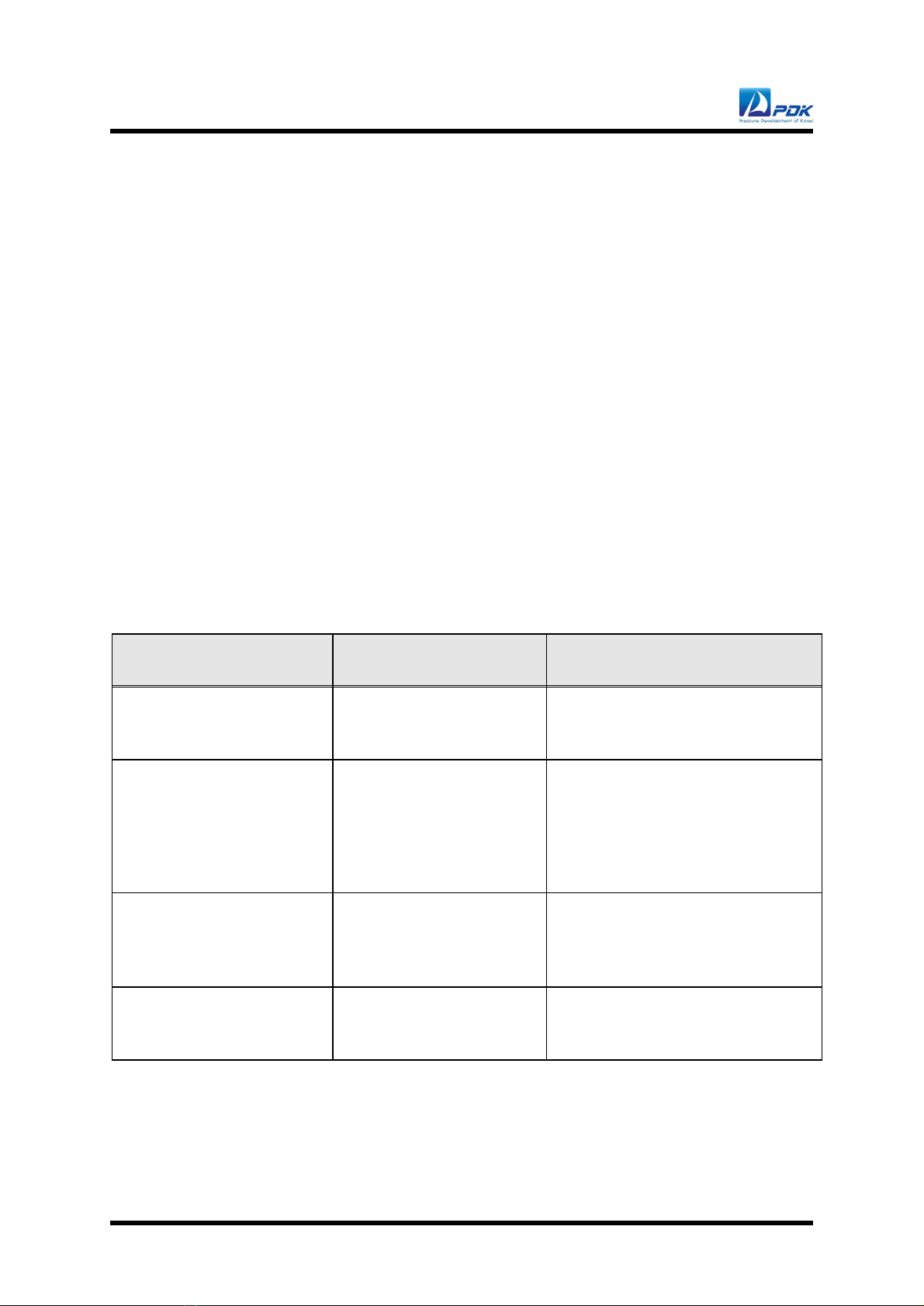
Page 14
SYMPTOM
PROBABLE CAUSE
SOLUTION
Piston suddenly floating or
descend.
Piston and Cylinder
contaminated.
Disassemble P/C module to
cleaning.
Piston does not rotate.
1. Piston position is fully
floating or in the bottom.
2. Motor trouble or
disconnected belt.
1. Pressurized or reduce pressure
to make correct piston position.
2. Replace motor or belt.
Piston dropped very
quickly.
Internal or external leaks.
Find the leaks point then tighten
or change the fitting to remove
the leaks.
Piston does not float.
Damaged Pressure
generator/controller O-ring.
Replace Pressure
generator/controller O-ring.
3. Trouble Shooting
3.1. Overview
PDPG has precision machining technology and high electronic engineering technology
therefore, it need to handle carefully.
Parts of the defect and the damage can lead to unexpected and dangerous results.
User needs to get training from who is well-acquainted with operation of PDPG
system.
3.2. Troubleshooting Checklist

PDPG-H Manual
Page 15
PDK AUTHORIZED SERVICE CENTER
COMPANY
ADDRESS
TEL.
FAX.
e-mail
PDK Co., Ltd.
10-6, EXPO-RO 339 BEON-GIL, YUSEONG-GU,
DAEJEON, KOREA ZIP 34122
Solution for Pressure
Measurement & Calibration
Table of contents
Other PDK Test Equipment manuals


Popular Test Equipment manuals by other brands


Multi-Amp
Multi-Amp CB-832 instruction manual

Sonel
Sonel P-4 user manual

Gossen MetraWatt
Gossen MetraWatt METRISO PRIME 10 operating instructions

OfiTE
OfiTE 171-193-6K instruction manual

Horotec
Horotec VIBRATO MSA 19.709 operating manual

Keysight Technologies
Keysight Technologies InfiniiVision 1000 X Series user guide


