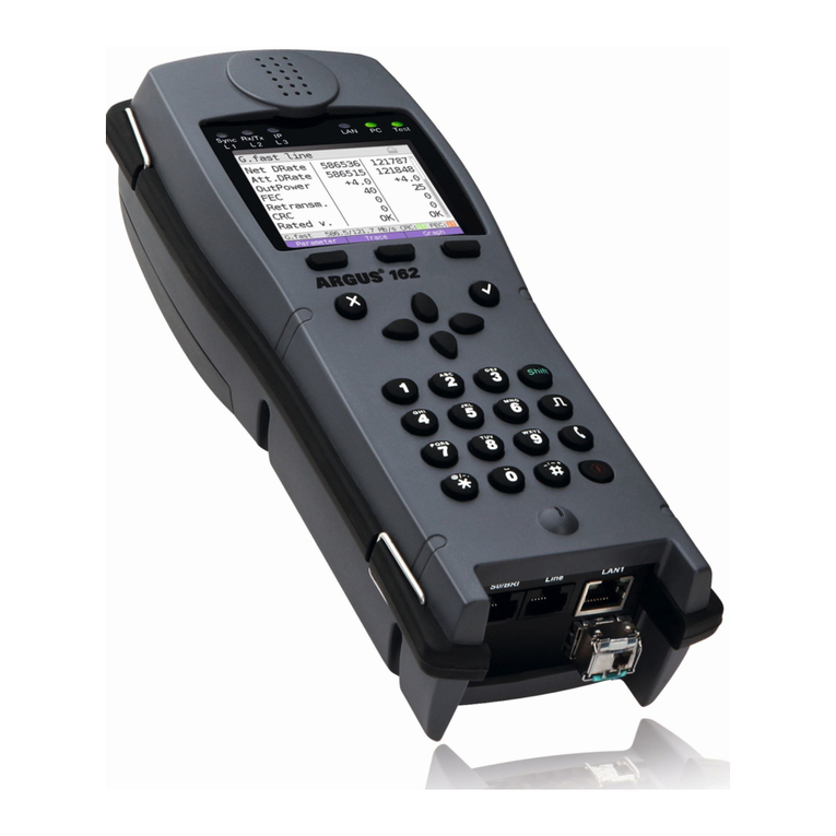
Intec ARGUS 300 User manual

ARGUS
ARGUS Copper Test Manual 1
ARGUS
Copper Test Manual
Version: 1.90 / EN
for ARGUS 300 and ARGUS 260
Important note:
Depending on the range of functions supplied, various menu options or functions may be
hidden.

ARGUS
2ARGUS Copper Test Manual
© by intec Gesellschaft für Informationstechnik mbH
D-58507 Lüdenscheid, Germany, 02/2022
All rights, including translation rights, reserved. No part of this work may be reproduced,
duplicated or disseminated in any form (print, photocopy, microfilm or any other method)
without written consent.
All rights are reserved. No one is permitted to reproduce or duplicate, in any form, the
whole or part of this document without intec´s permission.

ARGUS
ARGUS Copper Test Manual 3
1Introduction .........................................................................................4
2Safety information copper tests ........................................................6
3Copper tests ......................................................................................11
3.1 Copper tests multimeter ..................................................................11
3.1.1 Auto test .....................................................................................11
3.1.2 Voltage measurement (U= and U~) ...........................................13
3.1.3 Capacitive symmetry measurement (CSym) .............................15
3.1.4 Capacitance measurement (C) ..................................................18
3.1.5 Isolation resistance measurement (Iso.) ....................................22
3.1.6 Resistance symmetry (RSym) ..................................................24
3.1.7 Resistive fault location (RFL) .....................................................30
3.1.8 Loop resistance measurement (R) ............................................32
3.1.9 DC current measurement (I=) ....................................................34
3.1.10 Longitudinal conversion loss (LCL) ..........................................36
3.1.11 Near-end crosstalk (NEXT) ......................................................38
3.1.12 Signature detection/termination detection ...............................40
3.1.13 Fast cable check ......................................................................42
3.1.14 Remote kit control (Rem.) ........................................................44
3.2 Copper tests Oscilloscope ..............................................................46
3.2.1 Line Scope .................................................................................46
3.2.2 Graph functions .........................................................................48
3.3 TDR ....................................................................................................51
3.3.1 Graph functions .........................................................................53
3.3.2 Examples ...................................................................................56
4Appendix ...........................................................................................59
A) Hotkeys ..............................................................................................59
B) Software Licenses .............................................................................60
C) Abbreviations .....................................................................................61
D) Index ..................................................................................................64

1 Introduction
4 ARGUS Copper Test Manual
1 Introduction
ARGUS Copper tests
The copper tests for ARGUS 300 and ARGUS 260 enable you to detect dangerous
voltages and currents early on and reliably assess the physical quality of the line –
particularly when DSL synchronisation is not possible or the data rate is low due to
asymmetry, interference sources or other mechanical line problems.
Technical features of the ARGUS copper tests at a glance:
Copper tests Multimeter
- Multiple, preconfigured measurement profiles can be executed as an auto test.
-Voltage measurement enables measurement of the supply voltage, as well as
external voltages caused e.g. by contact between two wires or isolation faults.
- With the aid of capacitive symmetry measurement, it is possible to detect asymmetry
in the subscriber line that can result in signal distortions or transmission errors.
-Capacitance measurement detects interruptions as well as typical input capacitances
of connected devices and enables estimation of line lengths.
-Isolation resistance measurement reveals damage to cable isolation, moisture
penetration or oxidised contact points.
- With the aid of resistance symmetry measurement, it is possible to detect irregula-
rities in the subscriber line that can result in signal distortions or transmission errors.
-Resistive fault location (RFL) can display resistance to fault (Rx), distance to fault,
resistance from fault to short circuit (Ry), loop resistance (Rs), line length, and fault
resistance (Rfault).
-Loop resistance measurement aids detection of short circuits and estimation of line
lengths.
-DC current measurement can be used to detect emergency, external and normal
power feeds as well as breaks in the line.
-Unbalance measurement (LCL): This measurement uses a frequency of 1 MHz to
measure asymmetry in a line pair.
-NEXT measurement: Measurement of near-end crosstalk at a frequency of 1 MHz.
-Signature detection is used to detect the signatures and test terminations (PPAs)
connected to the subscriber line.
- The fast cable check verifies the correctness of a three-pole (Tip/Ring/Ground)
connection.
- The integrated remote kit control lets you remotely set the line end to the desired
state either manually or automatically using a variety of electronic instrument kits.
Copper tests Oscilloscope
-Line Scope: High-performance realtime Line Scope with display in time and frequency
range (FFT) up to 35 MHz
-TDR: Time domain reflectometer to measure line lengths and locate faults

1 Introduction
ARGUS Copper Test Manual 5
Note:
You can download the latest manuals at http://www.argus.info/service/downloads
or simply contact one of our service representatives:
intec Gesellschaft für Informationstechnik mbH
Rahmedestr. 90
D-58507 Lüdenscheid
Tel.: +49 (0) 2351 / 9070-0
Fax: +49 (0) 2351 / 9070-70
www.argus.info/en

2 Safety information copper tests
6 ARGUS Copper Test Manual
2 Safety information copper tests
There are the following safety specifications:
VDC 0 V to 200 V
VAC 0 V to 200 V
IDC 0 mA to 150 mA
ISO 105 VDC, max. 2 mA
R13 VDC, max. 15 mA
The following special instructions must be observed for the individual measurements:
Voltage
Be sure to observe the permissible measuring range specified above when measuring
voltage.
Capacitance/capacitive symmetry
Before measuring, make sure that the voltage thresholds given in the table below are not
exceeded during the measurement. Certain measurements can require a longer settling
time. An automatic “TRG-opt.” measurement can thus take some time.
Isolation resistance
Before measuring, make sure that the voltage thresholds given in the table below are not
exceeded during the measurement. During the measurement, the ARGUS can apply a
measuring voltage of up to 105 V max. 1 mA) to the line. Certain measurements can
require a longer settling time. An autotest can thus take some time.
Loop resistance/resistance symmetry
Before measuring, make sure that the voltage thresholds given in the table below are not
exceeded during the measurement. During the measurement, the ARGUS can apply a
measuring voltage of up ton 13 V (max. 15 mA) to the line.
DC current
Be sure to observe the permissible measuring range specified above when measuring DC
current. Make sure you connect the ARGUS in the circuit in series.

2 Safety information copper tests
ARGUS Copper Test Manual 7
Longitudinal conversion loss (LCL)/NEXT
Before measuring, make sure that the voltage thresholds given in the table below are not
exceeded during the measurement. When measuring LCL or NEXT using the ARGUS,
any type of additional measurement lead can falsify the measurement. Both the length
and the position of the measurement leads with respect to each other can influence the
measurement result significantly.
Signature detection/fast cable check/remote kit control
Before measuring, make sure that the voltage thresholds given in the table below are not
exceeded during the measurement.
Voltage thresholds
Measurement UDC (V) to UAC (Veff) to
R* 3,5 30
R-Sym* 30 30
ISO-R* 5 30
C* 17 17
C-Sym* 17 17
LCL 10 7
NEXT 10 7
Signature 3 3
Fast cable check** 5 30
Remote Box 3 3
* Measured on 200 kΩ load
** Loop limit value 10 kΩ

2 Safety information copper tests
8 ARGUS Copper Test Manual
Measuring accuracies copper tests:
Voltage:
DC voltage measurement (U=):
Measuring range: Resolution: Accuracy:
0 V - 9.99 V 0.01 V ±(0.5 % + 2 digits)
10 V - 200 V 0.1 V ±(0.5 % + 2 digits)
AC voltage measurement (sine, 50 Hz) (U~):
Measuring range: Resolution: Accuracy:
0 V - 9.99 V 0.01 V ±(2 % + 2 digits)
10 V - 200 V 0.1 V ±(1.5 % + 2 digits)
Frequency: 10 Hz to 200 Hz; 0.2 Hz; ±(1.5 % + 2 digits); sine
When measuring voltages, the input resistance depends on the measuring range:
- Measuring range 1: 0 V - 25 V; Input resistance: 1.694 MΩ
- Measuring range 2: 25 V - 200 V; Input resistance: 1.05 MΩ
As soon as the total of all voltages exceeds 25 V, the measurement is switched over.
Capacitive symmetry measurement (CSym):
Measuring range: Resolution: Accuracy of capacity diffe-
rence:
10 nF - 4 µF 0.01 nF 0.1% of the capacity to
ground
Capacitive measurement, measuring frequency 8 Hz (C):
Measuring range: Resolution: Accuracy:
0.01 nF - 9.99 nF 0.01 nF ±(4 % + 4 digits)
10 nF - 99.99 nF 0.01 nF ±(4 % + 4 digits)
100 nF - 999.9 nF 0.1 nF ±(3 % + 1 digit)
1 μF - 8 μF 1 nF ±(3 % + 1 digit)
* All specifications relate to a comparison measurement using film capacitors.

2 Safety information copper tests
ARGUS Copper Test Manual 9
Isolation resistance measurement with 105 V, max. 2 mA (Iso.):
Measuring range: Resolution: Accuracy:
0.1 kΩ - 99.9 Ω0.1 kΩ±(2 % + 1 digit)
100 kΩ - 999 kΩ1 kΩ±(2 % + 1 digit)
1 MΩ - 9.99 MΩ10 kΩ±(2 % + 1 digit)
10 MΩ - 99.9 MΩ100 kΩ±(5 % + 1 digit)
100 MΩ - 1 GΩ100 kΩ±(5 % + 1 digit)
Isolation resistance measurement with 8 V, max. 8 mA (Iso.):
Measuring range: Resolution: Accuracy:
0.1 kΩ - 99.9 kΩ0.1 kΩ±(2 % + 1 digit)
100 kΩ - 999.0 kΩ1 kΩ±(2 % + 1 digit)
1 MΩ - 9.99 MΩ10 kΩ±(2 % + 1 digit)
10 MΩ - 40 MΩ100 kΩ±(5 % + 1 digit)
Resistance difference (RSym):
Measuring range: Resolution: Accuracy:
10 Ω - 5 kΩ0.1 Ω± 0.2 % of RLoop ± 0.2 Ω
Resistive fault location (RFL):
Display of: Measuring ranges: Accuracy Rx at Lx/L = 0.1
Resistance to fault (Rx),
distance to fault
Loop resistance (Rs):
10..9999 Ω
Rs = 2000 Ω: ± 0.3 %
± 0.05 Ω
Resistance from fault to
short circuit (Ry)
Fault resistance (Rfault):
0..20 MΩ
Rs = 200 Ω: ± 1.0 % ± 0.06 Ω
Loop resistance (Rs),
line length
Fault resistance(Rfault)

2 Safety information copper tests
10 ARGUS Copper Test Manual
Loop resistance measurement with 13 V, max. 15 mA (Iso.):
Measuring range: Resolution: Accuracy:
1 Ω - 999.9 Ω0.1 Ω±(1 % + 3 digits)
1 kΩ - 9.999 kΩ1Ω ±(1 % + 1 digit)
10 kΩ - 99.99 kΩ10 Ω±(1 % + 1 digit)
100 kΩ - 999.9 kΩ100 Ω±(1 % + 1 digit)
1 MΩ - 9.999 MΩ1 kΩ±(2 % + 1 digit)
10 MΩ - 40 MΩ10 kΩ±(5 % + 1 digit)
DC current measurement (I=):
Measuring range: Resolution: Accuracy:
0 mA - 150 mA 0.1 mA ±(2.5 % + 3 digits)
Unsymmetrie balance at 1 MHz (LCL):
Measuring range: Resolution: Accuracy:
0 dB - 55 dB 0.1 dB ± 1.5 dB
55.1 dB - 65 dB 0.1 dB ± 3 dB
The length of the measuring leads can significantly affect the measurement. Therefore,
always use the original accessories for measuring.
Near-end crosstalk at 1 MHz (NEXT):
Measuring range: Resolution: Accuracy:
0 dB - 65 dB 0.1 dB ± 1 dB
The length of the measuring leads can significantly affect the measurement. Therefore,
always use the original accessories for measuring.
Reference conditions (calibration):
- Temperature: +23 °C to ± 5 °C
- Humidity: 50 % ± 20 %, relative, non-condensing
- Frequency of measurement quantity: 50 Hz ± 5 Hz, sine

3 Copper tests
ARGUS Copper Test Manual 11
3 Copper tests
The ARGUS displays the menu options "Copper tests multimeter" and "Copper tests oscil-
loscope" in the access menu. These tests can be used to detect dangerous voltages and
currents at an early stage and to reliably assess the physical condition of the cable.
In the following, the operation of the various functions is briefly presented. Since the results
are usually only available in graphical form, they can only be correctly interpreted in con-
junction with knowledge about the line on which measurements are being made. The
ARGUS supports you with various tools, such as the zoom or cursor function.
3.1 Copper tests multimeter
3.1.1 Auto test
The ARGUS executes various tests automatically, depending on the configured auto test
profile. Ten user-configurable profiles (including remote kit control) are available for auto
test.
The measuring ranges, resolutions and accuracies of the respective measurement may be
found in the chapter Technical data, see page 8.
Selection of the auto test (see picture on the left).
After selecting the "Menu" softkey, 10 CU Auto test profiles can be configured at "CU Auto
test Profile".
A voltage check is performed before every measurement (except current
measurement) in which the voltage limits given in the table (see page 7)
may not be exceeded.

3 Copper tests
12 ARGUS Copper Test Manual
Select the profile to be editied and open it with <Edit>.
The auto test it configured under Auto test configuration.
See the respective chapters for details on the individual measurements.
You can obtain further information on the auto test settings in the
ARGUSpedia on the instrument.

3 Copper tests
ARGUS Copper Test Manual 13
3.1.2 Voltage measurement (U= and U~)
Voltage measurement enables detection of e.g. connected accesses (such as POTS) and
supply voltages and external voltages, such as a connection to another line.
In AC voltage measurement, the frequency (10 - 200 Hz) is additionally displayed. This also
enables identification of call switching and coupled voltages as well as carrier or power fre-
quencies.
See the chapter Technical data page 8 for information on measuring ranges, resolutions
and accuracies of voltage measurement.
Selection of voltage measurement.
Voltage measurement starts automatically when the Copper tests are activated. In this
example, the
- Current voltage in volts
- Current frequency of AC voltage in hertz
- Minimum voltage in volts
- Maximum voltage in volts
are measured.
After selecting the "Menu" softkey, the following settings can be made:
- Input Resistance
- Remote Kit Command
- Remote Kit
- Information Bell
Note that unexpected or hazardous mixed voltages or hazardous
voltage peaks can occur.

<Hold>
<Go>
3 Copper tests
14 ARGUS Copper Test Manual
You can obtain further information on the settings in the ARGUSpedia on the
instrument.
The continuing measurement is paused.
Continues measuring.

3 Copper tests
ARGUS Copper Test Manual 15
3.1.3 Capacitive symmetry measurement (CSym)
With the aid of capacitive symmetry measurement, it is possible to detect irregularities in
the wiring that can result in signal distortions or transmission errors. The line must be open.
In a real line, a network of serial and parallel capacitances is formed between the individual
reference points, as illustrated in the following diagram.
The total capacitance Cab of the series connection of CaE and CbE is actually measured
between a (tip) and b (ring).
The measured value shows the mutual capacitance (Cm) value. This applies correspond-
ingly for measurements between a (tip) and ground (E) and between b (ring) and ground.
These measurements for the basis for calculating the actual values of Cab, CaE and CbE.
The calculated values are then used in determining symmetry.
Additionally, the absolute deviation of the two capacitances CaE and CbE with respect to
ground and the relative deviation are determined.
Relative deviation (in %) = 2x
Absolute deviation (in nF) = absolute difference (CaE-CbE)
The calculated values represent the actual values CaE, CbE and Cab for the individual
capacitances. As the capacitances with respect to ground CaE and CbE are particularly
important for the symmetry of a line, the absolute and percentage values are also given
here for the sake of clarity. The relative value should not exceed 1 % (recommendation).
The absolute deviation is of particular importance on extremely short lines, as even small
differences here can result in a higher-percentage deviation. It must be reviewed on a
case-by-case basis whether this is acceptable.
The line must be open. This can be achieved e.g. using the instrument kit
function "open circuit". A voltage check is performed before the measure-
ment in which the voltage limits given in the table (see page 7) may not be
exceeded.
Always make sure that no instrument kit is connected when measuring
capacitance on extremely short lines (< 100 m). If this occurs, the decou-
pling capacitance of the instrument kit may also be measured, which will
significantly falsify the measuring results. On the TS916, for example, an
additional capacitance of 3.3 nF is measured at a measuring frequency of
8 Hz.

3 Copper tests
16 ARGUS Copper Test Manual
See the chapter Technical data page 8 for information on measuring ranges, resolutions
and accuracies of voltage measurement.
Capacitive symmetry measurement settings
Selection of the capacitive symmetry measurement
After activating the capacitive symmetry measurement, the following is measured:
- Cm (operating (mutual) capacitance) (in nF)
- Cab (capacitance between Tip and Ring) (in nF)
- CaE (capacitance between Tip and Ground) (in nF)
- CbE (capacitance between Ring and Ground) (in nF)
- ΔC (absolute deviation between CaE and CbE) (in nF)
- Relative deviation (in %)
After selecting the "Menu" softkey, the following settings can be made:
- Wire Types
- Susceptibility
- Remote Kit Command
- Remote Kit
You can obtain further information on the settings in the ARGUSpedia on the
instrument.
When you select the susceptibility "insecure (fast)", the red warning
"ATTENTION: susceptible" appears on the display.

3 Copper tests
ARGUS Copper Test Manual 17
When a wire type is selected the specific capacitance and measured
operating capacitance are used to calculate the line length.
When a cable type has been selected, it is shown in the display.
Under certain circumstances, the capacitive symmetry measurement can
abort. Possible causes include the presence of an external voltage, absence
of a line or the existence of a loop.

3 Copper tests
18 ARGUS Copper Test Manual
3.1.4 Capacitance measurement (C)
Capacitance measurement shows the typical input capacitance of connected devices or
the capacitance of the open line.
See the chapter Technical data page 8 for information on measuring ranges, resolutions
and accuracies of voltage measurement.
Capacitance measurement settings
After selecting the "Menu" softkey, the following settings can be made:
- Wire Types
- Susceptibility
- Remote Kit Command
- Remote Kit
- Information Bell
The line must be open. This can be ensured using the instrument kit
function "open circuit". Before the measurement, a voltage check is
performed in which the voltage limits given in the table (see page 7) may
not be exceeded.
Always make sure that no instrument kit is connected when measuring
capacitance on extremely short lines (< 100 m). If this occurs, the
decoupling capacitance of the instrument kit may also be measured,
which will significantly falsify the measuring results. On the TS916, for
example, an additional capacitance of 3.3 nF is measured at a
measuring frequency of 8 Hz.

3 Copper tests
ARGUS Copper Test Manual 19
You can obtain further information on the settings in the ARGUSpedia on the
instrument.
When you select the susceptibility "insecure (fast)", the red warning
"ATTENTION: susceptible" appears on the display.
Once you have measured C-symmetry, you no longer need to measure
capacitance.

3 Copper tests
20 ARGUS Copper Test Manual
3.1.4.1 Calculating line length
Every telecommunication cable has a certain loop resistance and operating capacitance
per unit of length. As the type of cable laid is generally known, this value too is known. The
values are design-related and relatively constant, as the cables are laid in the earth and
subject to relatively minor temperature and humidity effects. However, a typical subscriber
line can consist of multiple segments. In these segments, the wire cross-sections, and thus
the technical specifications, can vary. These parameters can also be stored in the device. If
the C or R measurement is now carried out, an evaluation of the measured line is obtained
with regard to its probable length in relation to the selected cable type.
This can only be determined for a measurement between the Tip- and Ring-wires. The
measurements with respect to Ground can be subject to random influences and thus
cannot be specified with a general capacitance or resistance value per unit of length. The
line length calculations can then be compared with the line length, which is generally also
known, thus providing information about faults. Using the calculated value, you can roughly
compare the line lengths and conduct further fault-finding (e.g. with a TDR) in the event of
discrepancies.
A wire type must be selected to enable calculation of the line length using a C or R measu-
rement. The wire type can be selected and configured during or after the measurement.
You can obtain further information on the settings in the ARGUSpedia on the
instrument.
This manual suits for next models
1
Table of contents
Other Intec Test Equipment manuals
Popular Test Equipment manuals by other brands
Endress+Hauser
Endress+Hauser Proline Fieldcheck operating instructions
BASEWEST
BASEWEST TS-421 Calibration manual
artisan
artisan Tektronix SC 502 instruction manual
Klein Tools
Klein Tools RT310 user manual
Tektronix
Tektronix TBS1000B Series user manual
Keysight Technologies
Keysight Technologies N5990A user guide
