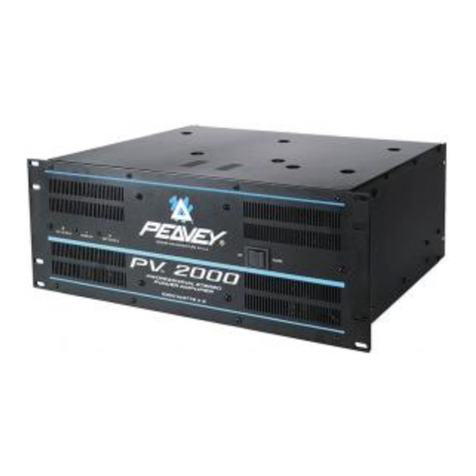
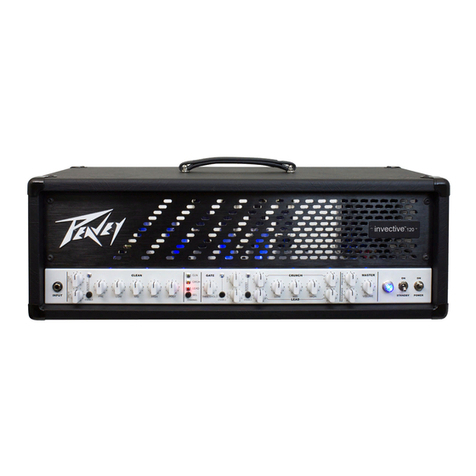
Peavey DECA/424 User manual

OWNERS
MANUAL

CHANNEL
A
•»’0
INPUT
SENSITIVITY
(1)
Maximum
luput
ksud
(minimum
sensitivity
rating)
is
achieved
at
the
fuJI
clockwise
setting,
A
setting
of
le£s
than
full
dockwiee
will
yield
lower
system
noise
atthee^epense
of
headroom.
Cslihratinn
indicates
sensilivjiy
m
volw/dBV
necessary
to
attain
full
available
output
OPERATION
NOTBr
The
input
sensiilvit.v
rating
of
a
power
amplifier
is
the
voltage
level
req
uired
to
dri
ve
the
eun
plificr
W
ful
I
output.
Calibration
in
dBV
allows
the
mixer
operator
to
‘'monitor”
the
power
amplifier
status
by
observing
the
dRV
level
of
the
mixer
l.RD
arrays
(on
mixers
so
equipped)
LKI)
LEVEL
IN
LOCATOR
(2)
A
mlihrated
LEI)
array
is
provided
to
visually
indicate
both
the
power
utilized
(in
percent^e)
and
head-
room
remaining
(in
dB).
The
bottom
L£D
is
illuminated
whenever
AC
powor
is
applied
as
a
pilot
indicator.
DDT*
COMPRESSION
Each
of
the
two
internal
p^wer
amplifiers
is
equipped
with
Pea-
vey’s
DDT"*
CcimpTession
(U.S.
Patent
4318,003).
The
DDT
circuits
will
automatically
engage
to
pre¬
vent
dipping
distortion
mthin
the
power
ampliPera.
DDT~
ACTIVE
LED
(3)
Dluminatea
when
DDT'
compKa-
aion
is
taking
place.
With
the
DDT
IN/OUT
switch
in
the
“Out”
posi
tion,
tho
LED
Is
defeated.
OPERATION
NOTE:
It
is
D
orm
al
for
the
DDT'
LBD<a)
lo
flash
occasionally
during
ampUCec
operation.
If
the
LED(s}
remain
on
continuously,
additional
headroom
is
needed.
In
sooie
cases,
this
may
mean
that
the
particular
applica¬
tion
requires
a
more
powerful
ara-
plifier.
INPUT
SENSITIVITY
(I)
(Eingangs'Em
p^ndl
ichkei
I)
Die
maximale
Einganga-VerstSr-
kung
(uiedersto
Erop^dlichkeit)
wird
hei
voll
im
IJhrzeigersinn
gedffneten
Kegler
erreieht.
£ei
wenigergenffrietem
Regler
wird
einp
Vermiodernng
des
Rauschens
erreicht,
allerdings
auf
Kesten
der
Obereteuerungsfestigkeit
.
Die
auf
gedruckte
KaKbrierung
zeigt
die
bondtigte
Empfindlichkeit
in
VoIt/dBV
an,
um
die
voile
Aus-
gangslei
stung
2
U
erreichen.
OPERATION
NOTE:
(ANWENDUNGS-HINWEIS:)
Die
Eingangs-EmpflndUchkeit
dec
Endstuie
skllt
die
Spannung
in
Voh
dar,
welche
bentttigt
wird,
um
die
voile
Ausgai^ffileietung
des
Ver-
siarkers
zu
erreichen.
Die
Kali*
brierunf
in
dBV
erlaubl
dem
Be*
diener.
den
Zueland
der
Endetufe
duich
Beobaebtender
LED’Anzeige
am
Mischpult
2
U
beurteilen,
falls
dieses
cntsprechend
auegertistetist.
LED
LEVEL
INDICATOR
(2)
j
LED-Pegelanzeige)
F.ine
kalibrierte
LED-Pegelanzeige
sowohi
die
verwendete
Lei-
stung
(in
Prozenten)
wie
aueh
die
verbleibende
OberstcucTungsrc*
serve
(in
d£)
aus.
Die
unterste
LED
(Pilot-LKD)
Isuch-
tet
zur
KontTolle
immer
wenn
daa
Oerat
oingsschaltet
ist.
DDT-
COMPRESSION
(DDT'”'KompressiuD)
Jeder
der
zwei
intemen
Endstufen
iet
mit
Peav
ey’8DDT"-KomprQ88iDn
(U.S.
Patent
4
;il8,053)
ausgeetattet.
Die
I)nr'“*KomptGssion
wird
auto-
matisch
alciiviertumVerzerraf^n
durch
zu
huhe
Pegei
vorzabeugen.
DDT-ACTIVE
LBD<3)
Leuchtet
auf,
wenn
DDT^'Kompres-
aion
einsetzt.
Wenn
aich
der
DDT-
Schalter
in
“Out’-Position
bofindet,
iat
LED
ausgsachalUt,
OPERATION
NOTE:
(ANWENDUNGS*
HIN
WE
IS;)
Ein
seitweihges
Auflcucbten
der
DDT'"-LED{8)
ist
normal.
Bio
stondigsB
Aufleuchton
der
LED(8)
hingegen
bsdeutot,
dall
die
Cbcr-
steuemngsreserve
der
Endstu
fe
er*
BchOpft
ist.
und
da8
ftir
diese
Anwendung
eine
etarkere
Endstufe
eingesetzt
warden
aullic.
INPUT
SENSITIVITY
(I)
(Seoaibilit^
d’entree)
Le
gain
augmente
cn
toumant
le
bouton
dans
Is
sens
dee
aiguilles
d’une
montre.
Lea
positions
inf^ri*
euros-au
maximum
diminueront
le
niveau
de
bruit
de
fond,
an
d^tri*
meiit
de
la
reserve
de
puissance.
L’
echelle
indlque
la
sensibilite
et
le
niveau
en
volts
n^cessairc
poor
at-
temdre
la
pui
ss
an
ce
d
e
e
ortie
maxi
TTinm,
NOTE:
Le
sensibilite
d'entree
d’uo
ampli*
ficateur
de
puiasance
oat
Ui
tension
n6ceedairc
pour
atCcindre
la
puie*
sance
maximum.
L’SdicHeen
dBV
permet
de
visualiser
la
charge
da
ramplificateur
en
la
rappOTtant
aux
indlcateurs
de
niveau
de
sortie
du
mfelangeuj.
LEVEL
INDICATOR
(2)
Gndicateur
de
niveau)
Echelle
de
diodes
esJibr^e
qui
In-
dique
i
la
fois
la
puissance
utilis^e
(en
pourcentage)
et
la
rbaorve
dis-
ponible
(en
dB).
La
diode
du
bas,
tcmoiit
de
mieo
en
route,
s’allumc
d^s
que
la
tension
secteur
est
ap-
pliqu4e
al'apparei).
DDT"
COMPRESSION
(Compression
*’DDT”}
Chacun
dee
deux
empJiflcateiirB
de
puiseanoc
incorpor^
est
^uipe
d'un
circuit
de
compression
PEAVRY
nnr
(brevete
4.3lA053>.
Ce
circuit
ae
met
automatic
uement
en
service
cn
caa
de
besuin
pout
^ter
une
distorsiun
par
^cr^age
dans
les
amplis
de
puissance.
DDT-
ACTIVE
LED
(3)
(Temoin
de
DDT|
S'aUume
loraque
le
circuit
de
com*
press
ion
DDT’*
intervient
Loesque
la
DDT
e5t
mise
hois
service
par
rinterrupleuT,
le
temoin
ezl
inopirarit
OPERATION
NOTE;
(Note)
S’il
ost
normal
que
le
temoin
do
DDT'dignote
occasiorm^^lementdij-
rant
le
fonctionnement,
un
a
Ho¬
mage
continu
indlque
un
manque
de
raaerve
de
puissance.
Dans
cer¬
tains
cas,
cedindiqueiaque
(’appli¬
cation
nacessite
une
ampIlflcatloQ
plus
puisaentc.
CHANNEL
B
^
-10
INPUT
SENSITIVITY
{Seuaibilidad
De
Entrada)
La
ganancia
maxima
de
entrada
(grado
mdximo
de
soneibilidad)
ee
alcanzado
girando
el
control
com-
pletamente
a
la
derecha
Si
no
up
coloeael
control
completamenteala
derecha
producird
conjuntoa
mas
bajoa
deruidu
a
costa
del
“head*
room”.
La
calibrod^n
indica
sensi*
bilidad
expresada
en
volts/dBV
nc
-
cesarioE
para
obtonor
toda
la
salida
disponible.
OPERATION
NOTE:
(Nuta
De
Operacion)
EJl
grade
de
sensibilidad
de
entrada
de
un
ampiificador
ee
el
nivel
de
voltage
requerido
para
hacer
fun-
cionar
un
ampiificador
a
eu
poten*
cia
maxima.
La
calibrarion
RndBV
permite
al
operador
de
la
m^la*
dora
munitorear
cl
puder
del
ampli*
licador
obsezvaitdoel
nivel
de
dBV
de
loa
focos
indicadoree
dc
la
mez*
cladora
(en
las
mezclodoras
que
lo
incluyan}.
LED
LEVEL
INDICATOR
(2)
(Focos
IndicadorDe
Nivel)
Una
lliiea
de
focos
indicadores
es
piovista
para
indicar
viaualmcnte
tanto
el
podcr
utilizado
(en
porecn-
taje)
como
el
“headroom”
diaponi-
ble
exproeado
en
DB.
La
parte
inferior
de
la
llnea
ee
ilumina
siempre
queest^
ccnectado
el
aparahJ.
DDT'
COMPRESSION
{D
DT
C
omp
r€Si6ii)
Coda
one
dc
loe
amplificadoreB
in-
temoa
eetas
equipados
con
el
sis-
tema
de
DDT
compreaidn
(U.S.
Pa*
tente
4,318,053).
El
circuito
DDTse
enciende
autamaticaniente
para
prevenir
distortion
dentro
de
Ids
ampliflcadorcs.
DDT’*
ACTIVE
LED
(LED-actlvo
del
DDT
Se
iiuRiina
cuando
la
compresion
deJ
DDT*ocurre.
Cuandoel
Beleclor
del
DDT
esia
en
la
pnmeion
halada
los
LED
36
deaactivan.
OPERATION
NOTE;
(NuU
Do
O|>dracion:)
Ea
normal
para
el
DDT’"
(foco
indicador)
prender
ncasionslmente
durante
una
operacibn
normal.Si
la
pan
tall
a
digital
permanece
encen-
dida
continuamente,
es
neceeario
m&B
“headroom".
En
algunoe
casoa
8«
requeritd
de
un
ampliRcador
con
mds
podor.

THERMAL
FAULT
LED
<
4
)
Illuminates
when
the
thermal
pro*
tection
circuitry
U
engaged.
The
LINE
PAUl/r
LED
will
ai^illumi*
nete
when
the
unit
ia
in
thermal
protect
mode.
OPERATION
NOTE:
Thia
unit
is
equipped
with
auto*
raatic
resetting
thermal
protection.
If
extremely
high
operating
tem¬
peratures
cause
the
protection
dr*
cuit
to
engage,
the
pilot
LEI^s)
will
cease
illuminating
and
the
fan
will
continue
to
run.
Once
it
has
cooled
suiRciently
the
protection
dicuit
will
disengage
and
the
amplifier
will
be
re-enabled.
Continued
ther¬
mal
ceding
indicates
a
load
pro¬
blem
exists
(shoreed
cable
or
the
total
speaker
load
is
too
low),
or
there
is
inadequate
ventilation.
LINE
FAULT
LED
(
6
)
Illuminates
to
indicate
an
mterrup-
tloR
in
amp
operation
due
to
any
fault
condition.
POWER
SWITCH
(81
U
dpress
to'
‘
On”
position
to
turn
on.
THERMAL
FAULT
LED
(
4
)
Leuchtet
auf,
wenn
der
VerstSrker
Qberhitzt
iat
bzw.
wenn
der
Uberhitzungsschutzschaltec
akti-
Tiert
iet.
OPERATION
NOTE;
(ANWENDUNGS-HINWEIS:)
Dieses
Gardt
ist
mit
einem
Uher*
hitatmgsechutz
mit
sutomatiacher
RCickatellung
ausgarnelet.
Beim
Auftrewr
esirem
hohet*
Betriebs-
temperaturen
wird
de;
Schuts
ak*
tiviart
und
das
GerSt
susgeschalCet
Dabel
erloschen
auch
die
Pilot*
LED(s),
wfihrend
dcr
Ventilator
eingeschaltet
blelbt.
Nach
aus-
mchsnder
Abktihlung
wird
der
Schulz
aufgehchsn
und
das
GerSt
wleder
eingeschaltet
Elne
etandlg
wledeikehrende
Aktivlerung
des
Schutzee
deutet
auf
ein
Ausgangs-
ProbLem
(KaheLKurzschluQ,
Geeamt-lmpedanz
des/der
ange-
Echloseenen
Lautsprecher
2
U
ni&
drig),
Oder
auf
ungenugende
Ven*
dlacion
(Hitzastaul.
LINE
FAULT
LED
(
5
)
Zeigt
durch
Autleuchten
an,
da
3
der
Betrieb
des
VeraMrkers
aua
irgend*
welcbenF^ilergnind^
unterbrochen
ist
POWER
SWITCH
(
6
)
<NsCz6cbnltdr}
Zum
EinsehaJten
in
Position
*'On"
driicken.
THERMAL
FAULT
LED
(
4
)
(T
6
moiD
de
protection
tbernijque)
Indique
Pinter
ven
tion
de
la
pro¬
tection
thermique.
En
cas
de
surchauffsjetemoin
LINE
FAULT
s'alliune
sussi.
NOTE;
Cet
appareil
est
6
quip
6
d’uiie
protec¬
tion
tbemiqus
irisrmemsnt
auto-
matique
Au
cas
oii
la
tampdrature
de
fonctionnement
depasserait
la
limite
autonste,
ta
protection
arrfi-
(era
Pappareil,
tteindia
la
diode
et
maintiendza
le
ventllatear.
Aprie
refroidissment,
Pappareil
se
remet-
tra
en
route
de
lui-m^ma.
Des
airtts
rep^s
indiquent
un
pio-
bl
6
me
h
la
sortie
{cAble
en
court-
circuit
DU
impddance
dc
charge
trop
falble),
oii
nne
ventilation
ineuf-
fisante.
LINE
FAULT
LED
(
5
)
<T
6
moin
de
dgfaillaoca)
iivlique
un
arr&t
de
fonctionnement
de
Vappareil,
quelle
qu’en
eoit
I'or^line.
POWER
SWITCH
iS)
(laterruptour
Power
Marche
Arr
4
t)
Appuyer
pour
mettre
Vampli
soue
tension.
THFJIMAL
FAULT
LED
(
4
)
(LED-falla
ter
me
1
)
Se
ilumina
cuando
el
circuilo
de
protecdon
termal
es
activado
El
LED
de
I
a
lin
ea
de
faha
se
iluminara
tambien
cuando
la
unidad
este
en
mode
de
protecdon
termal.
OPERATION
NOTE:
(Nota
De
Operaoion)
Eata
unidad
este
equipada
con
un
protector
tdrmicc
de
reencendido
automitico.
Si
temperaturas
extra*
mddamentealtas
son
alcanzadas
se
activard
el
dreuite
protector,
apa*
gando
el
focc
piloto
con
el
ventila*
dor
funcionando.
Una
ves
qne
el
aquipoaeha
enMado
losufidenteel
dreuito
ae
desactivard
dejando
operative
el
equipo
nuevamenu.
Cuando
eats
ddo
de
protecdon
oenr*
r&
a
menudo
es
indicacidn
de
un
prcblemn
de
sobrecarga
(cable
en
corto
dreuito
o
la
carga
total
de
las
bocinae
es
may
baja)
o
de
inade-
cuada
ventilaoidn.
LINE
FAULT
LED
(
5
)
(LED
>
linea
de
falla)
Se
ilumina
para
indicar
una
inter*
rupcion
en
la
operacion
del
amplifi*
cador
debida
a
ab^un
falloextstente.
POWER
SWITCH
(
8
)
{Power
Switch)
Prasione
eate
intamptor
para
en*
render
el
apamto.
CAUTON
TO
pRivfM’
’HE
0*
pcpieano
^
a*
<
SD
CO
O'(«(•:«
E-'>41
(
TO
no
S4A«'Ct
PeBSOr^atL.
CKB'dr-CiAfTU
LUrfC
AVIS
KCHCCf
lEcmiOA
INEPI^ECUVRB
BEMBu&LeBBMnri
tx
MiM
-roe
et
w
esc
taiB
Bjilt
jwiaue
ANOBarru-Pfurvuc
rX'EUIi'COMCl.lEB«-'*'<T>iCLI(4l<&r03
dCUSk
BCd'^Vlirc
OEV<f
(
ntfSUkVT
*9
SJEPERT
J
Ct
OhW
16
»
ETT
%JliS
OECAy'424
DQftJVgBeiQNAMPUCi£ia
-CHAf^BLA
CHAhWELC-
•
••touc
-
'.»•
.
'
B.VJI,
.
r<(»eiP'*ME
VMiO;
.U
IP
tr.
BALANCED
INPUT
(
7
)
A
H"
slereo
(RTS)
jack
is
provided
for
balanced
input
termination.
LINE
OUT
(
8
)
A
‘A"
Bterero
phone
jack,
paralleled
with
the
balanced
input
jack
May
be
u
86
d
as
a
bal
an
ced
or
unbalanced
input
or
line
out.
For
balan
ced
opera¬
tion
use
a
etcreo
(RTS)
plug
and
balanced
cabling.
OPERATION
NOTE:
Using
thie
jack
with
a
^
4
'
mono
pli^
unbalances
the
input
Using
this
jack
as
a
"Y-out
'to
an
unbalanced
input
on
another
piecs
of
equipment
will
unbalance
all
the
paralleled
inputs.
BALANCED
INPUT
(
7
)
Die
SlerBo-(RTS)
Buchse
ist
fQr
syiometrische
Bmgdngc
vorgeaehen.
UNE
0
UT(
8
)
Die
StereO'KlInkenbuchse
enispricht
dem
symmetrischen
Klinkenein*
gang.
Sie
karm
als
symnsetrischer
oder
uneymmetHscherEingangoder
Lice
Out
gebraucht
werden.
Fur
symmetrischen
Betrieb
braacht
man
einen
Stereo-Stacker
und
eymmetriacha
Varkabelung.
OPERATION
NOTE:
Der
Gebrauch
disBer
Buchse
mit
einair
Mono-Klinkensteoker
macht
dieaen
Eingang
unsyminetflsch.
Der
Gebrauch
dieser
Buchse
als
ein
“YGut*'
zudnem
unsymmetriBchen
Eingang
einee
aederen
GerStes
macht
alls
paralleUn
Eing&nge
unsymmetnacti.
BAIANCED
INPUT
(
7
)
(Entree
sym^trlque)
Prise
jack
6,05
mm
at^reo
pour
entire
Bymttrique.
LINE
OUT
(
8
)
(Sortie
Ugne)
Prise
jack
6,35
men
ster^
branehte
en
parallde
sur
la
prise
d'entree
sym^que.
A
uUIiser
comrue
prise
d'entree
ou
de
sortie
{pour
repi*
quage),
en
sym^trique
au
asyme^*
que.
Four
c&bler
en
eym^trique,
utiliser
une
fich
a
j
ack
6,35
mm
etkr^
et
un
cflblage
i
2
cooducUurs
plus
blindage.
NOTE:
Le
fait
d’inserer
unetichejack
mono
dens
Cette
prtse
rend
auiomatique*
ment
I'entree
asym^Crique,
De
metne,
son
utilisation
enrepiquage
BUT
un
quelconque
appardl
asym^
trique
rendra
asycn^triques
touUs
lea
prises
qui
y
sent
branch^
en
parallels.
BALANCED
INPUT
(
7
>
(Entrada
Balanceadal
Se
provee
una
eotrada
de
'
4
'
(RTS)
para
ellminar
la
entrada
balanceada.
LINE
OUT
(
8
)
(l.inea
de
Satida)
Una
entrada
de
14
'
eetereofnnica
en
pataleloconia
entrada
balances
da
puede
ser
usada
cemo
entrada
baleoiceadaono
balanceadaocomo
linea
de
salida.
Para
operar
balancoado
use
un
conector
de
estereofonico
(KTS)
y
cable
balanceado.
OPERATION
NOTE:
(Nota
Operaeional)
Si
se
utiliza
esta
entrada
eon
un
conector
de
Vt"
monofonico
es
desbalancea.
Si
se
utiliza
eata
entrada
para
hacar
una
"Y”
de
salida
hacia
una
onCrada
no
baUnceada
u
otro
equipo,
des-
balanoeare
tedes
las
entradae
paraJelaa.

DDT”
IN/OUT
SWITCH
(9)
PDT'*
compression
is
defeated
with
the
switch
in
the
"out”
position.
DDT
should
beenahUd
at
all
times
to
protect
speakers.
COOLING
FAN
(10)
To
protect
agaiiist
possible
over¬
heating,
(he
ampUhoT
ia
supplied
with
ao
intomal
cooling
fan.
The
fan
will
operate
at
all
times
when
the
amplifier
is
turned
on.
To
ensu
re
efficient
operation,
the
fan
exhaust
port
and
air
intake
porta
should
be
unobstructed
at
all
tines.
SPEAKER
OUTPU*rS
<ll>
Provided
for
connection
of
external
apeaker(s).
Mirriniuin
total
Itnpe*
dance
is
4
ohms.
t'USE{12)
The
fuse
is
lo
cated
vnthi
tv
the
cap
of
the
fusehuldei.
If
the
fuse
should
fail,
IT
MUST
BE
REPLACED
WITH
THE
SAME
TYPE
AND
VALUE
IN
ORDER
TO
AVOID
DAMAGE
TO
THE
EQUIPMENT'
AND
TO
PREVENT
VOIDING
THE
WARRANTY.
If
the
amp
repeatedly
blowa
fuses,
it
should
be
taken
lo
a
qualified
aervice
center
for
repair.
WARNING:
THE
FUSE
SHOULD
ONLY
BE
REPLACED
WHEN
THE
POWER
CORD
HAS
BEEN
DISCONNECTED
PROM
ITS
POWER
SOURCE.
AC
LINK
CORD
SOCKET
<13)
E^ovided
to
accept
the
removable
AC
line
cord.
LINK
CORD
(120V
products
only)
For
your
safety,
we
have
incor¬
porated
a
d-wire
U&e
(mains)
cable
with
proper
siounding
facilities.
It
la
not
advisable
to
remove
the
ground
pir\
under
any
circum-
etenccs.
Ifitis
necessary
to
vise
the
equipment
without
proper
ground*
)ng
facilities,
suitable
grounding
adaptors
should
he
used
Less
noise
and
greatly
reduced
shock
hazard
exieCfi
when
the
unit
la
operated,
with
the
proper
grounded
recepta¬
cles.
DDT-
IN/OUT
SWITCH
(9)
Wenji
derSchalter
in
‘'Out”*Position
steht.
iat
die
DDT’*'‘Koinpres8ion
ausgescbaltet
DDT
aoUte
eigen
tlich
unmei
eingeechaltet
acin
um
den
Lauteprechcr
zu
achutsen.
COOLING
FAN
(10)
(KiiKl-Ventilator)
Um
einer
moglichen
Ufaerhitzung
vorzubeugen
istds*
Verst^kerrait
einem
Ventilalor
ausgeetattet,
der
bei
eingeschaltetem
GeiSt
imnier
Ifiuft.
Um
die
Wirkung
dea
Venti¬
lators
nicht
herunterzuseizen
soil-
ten
die
Luftein-
und
Aualaeed^-
Qungen
oic
blockiert
warden.
SPEAKER
OUTPUTS
(11)
(Speaker
Outputs)
Vorgesehen
filr
den
Anschlufi
ex*
terner
Lauts
precher.
Die
Gesomtim*
pedanz
von
4
Ohm
darf
nicht
unter-
Bchiittea
werden.
FUSE
(12)
(Fuse)
Die
Sickening
iat
in
der
Kappe
des
Sichcrungshalteraplaziort.
F^la
die
Sickerung
duxchgobrannt
ist,
darf
sie
GusachlieBlich
durch
eine
Siche-
rang
desselben
Typs
und
derselben
Rel&stbarknlt
eT8et?;t
werden,
da
soiiBt
das
GerSt
beschfldigt
werden
kann
und
der
Garaniie-
Anapruch
crlischt
Achtungl
Dis
Sicheruug
darf
aus-
echlioBlich
bei
gezogeoem
Nets*
stacker
gewechselt
warden!
AC
LINE
CORD
SOCKET
(13)
(Stromaiiechlas
a)
Zum
Anscblicssen
dee
abnebm*
baren
Wechselstrom-Kabela.
LINK
CORD
(120V
products
only)
(nuc
bei
120
Volt-Geraten)
Zu
Ihrer
Siclrerbeit
haben
wir
daa
Geratmit
einem
dreiadrigen
geetde-
ten
Netzkabel
versehon.Efi
ist
unter
kainen
Umstandenempfehlenswart
den
ErdunEskontaktdes
Anschlufi-
kabels
zu
^osen.
Falls
es
notwendig
sein
sollte.
das
Equipment
ohne
die
vorgesehene
Erdung
zu
beCreiben
empfi^lt
sich
die
Vetwendung
einca
Groundinjg
Adaptors.
Die
ge-
hngetenStoTgerauscdieunddie
hoch-
ste
Sicherhett
vor
elektrisd^
Schl
a*
wird
jedocb
dumb
die
Benut-
TungdsrvorgSfleheneD
Erdungemog*
llcbkeiten
erreicht^
DDT-
[N/OUT
SWITCH
(9)
(loteiTupteurde
DDT)
La
compreaaioD
DDT*
estmise
hors
circuit
loraque
le
bouton
cat
tire.
Pour
prot4gor
lee
haut
pcrleurs,
nous
recommandons
de
la
laisscr
en
service.
COOLING
FAN
(10)
(Vcntilateur)
Pour
eviter
une
^vantuelle
sur*
rhauffc,
I'amplificateurcomporteun
ventUateur
Int^gr^
Celui-ci
fooc*
tionce
syatematiquemezit
loraque
Pappareil
est
sous
tension.
Veiller
h
ne
pae
gdner
son
foactioonoment
cn
obstmant
lea
ouies
d'entr^o
et
da
sortie
de
Pair.
SPEAKER
OUTPUTS
(II)
(Sortiea
haut-parl^irs)
Prises
de
sortie
vers
hautrparieur{s)
exterieur
(a).
L’imp^ancc
i^ul-
tante
devra
^le
au
minimum
de
4
ohms
a
ur
chaquo
priso.
FUSE
(12)
(Fusible)
Le
fusible
ac
trouve
a
i\nterieur
de
son
support.
En
cae
do
coupurc
du
fusible,
il
doit
$tre
remplace
par
le
MEME
TYPE
et
las
MRMR
VA¬
LE
UR
ponr
iter
tout
DOMMAGE
d
L'APPAREIL
et
cooaervec
le
DROIT
a
la
GARANTIE.
Si
le
fusi¬
ble
claque
de
mani^re
repitee,
eoumettrel'apparoil
d
tm
cechnicicn
quali£6
pour
v^riRcation.
ATTENTION:
Le
FUSIBLE
nedoit
dtre
remplace
qu'APRES
AVOIR
DEBRANCHE
LE
CORDON
SEC-
TEUR
DE
lA
PRISE.
AC
LINE
CORD
SOCKET
(13)
(Prise
socteur)
Prise
ds
branchement
du
cordon
secteur.
LINE
CORD
(Cordon
secteur)
Get
appareil
est
^uipe
d'une
fiche
aecteur
k 3
broches
avec
mise
h
la
torre.
La
misc
k
la
torro
dimirue
le
bruit
de
fond
et
assure
la
slcuritc
n4cees
sire
k
I'em
p
loi
de
cet
apptaeil
^lectrique.
DDT'
IN/OUT
SWITCH
(9)
La
compreaion
del
DDr**
cs
desac-
tivada
con
el
selector
bacia
afuera.
El
DDT
debs
astarsiempreactivado
con
el
Hn
de
proteger
las
borinaa
COOLING
KAN<10)
(Ahanico)
Para
proteccihn
del
sobrecalenta-
miento.
el
umpHflcador
tiene
an
abanico
intemo-
El
abanico
opera
aiempre
que
eatd
cncendido
el
apa-
rato.
Para
quo
opere
eiidontemcnts,
las
secciones
de
ontrada
y
salida
de
aire
deben
de
inantenerAe
sin
ob-
struccioncR.
SPEAKER
OUTPUTS
(11)
(Salida
de
Bocinas)
Pru
vista
para
la
conexion
do
bodn
as
externae.
El
ralnimo
total
de
Impe-
dancia
ea
dc
4
ohms.
FUSE
(12)
(Fusible)
£1
fusible
so
encuentra
bcalizado
dentrodclacapaula
del
portafueible
si
el
fueible
se
quema
u
falla,
DE*
BERASKR
REPUESTOCON
UNO
DRL
MIvSMO
TIPO
Y
VALORES,
PARA
PREVENIR
DAf50
AL
APARATO
Y
CANCBLAR
LA
GARANTIA.
Si
cl
eparalo
quema
loB
fnsiblca
repetidamenU,
vea
si
estA
oonectado
a
un
tomacorriente
con
el
vcltaje
adecuado.
si
esto
es
corrento,
entcnces
deaconectele
y
llevelo
a
revision
por
un
tecnico
autorizadu.
ATEN
CION:
El
fusible
deberd
scr
ceemplazado,
solo
cuando
el
cable
de
aUmontacion
sea
deeconectadn
del
Comacorriente
AC
LINE
CORD
SOCKET
(L3)
(Baohufe
pare
cable
de
Poder)
Proviato
para
enchufar
el
cable
de
eomenta
LINE
CORD
(1200
Solamente)
Para
su
protecion
hemoa
incor-
porado
un
cable
dc
3
alambres
con
tierra.
No
ee
recomendable
el
re*
mover
la
pa
ta
de
tierra
bajo
ni
nguna
circumsiancia,
se
recomienda
un
adaptador
eo
casu
ntcesaria.
Eeiu
reducira
ruidos
y
peUgrosos
cor-
rientazoB.

DECA/424
SPECIFICATIONS:
FREQUENCY
RESPONSE:
‘•0»-l-5db
10
Hz
to
20
kHz
@
1W
RMS
into
4
ohms.
RATED
POWER
OUTPUT:'
200
Wans
RMS
per
channel
:nlo
4
ohms
with
less
than
0.3%
Total
Harmonic
Distortion
TOTAL
HARMONIC
DISTORTION*
Less
than
0.3%
@
200
watts
RMS
per
channel
Into
4
ohms
TRANSIENT
INTER
MODULATION
DISTORTION:
None
Present
(0%TIM)
OUTPUT
SLEW
RATE:
The
am
pli
tier
outp
ut
slew
rate
Is
I
nterna
I
ly
coniro
n
eO
lo
opU
m
izB
p
h
ase
linearity
ano
improve
transient
response.
Due
to
the
nature
of
the
amplifier
design
and
the
internal
signal
conditioning
circuitry,
it
cannot
slew-rate
limit,
HUM
A
NOISE:
Greater
than
85
d6
bdiow
full
power
(20
H2
to
20
kHz)
INPUT
SENSITIVITY:
1
.(3V
RMS
for
200
watts
into
4
ohms
LOAD
PROTECTION:
Short
clfcu^t
curreni
limll.
Thermal
overload.
Turn
oh
ar>d
turn
off
transient
muting.
THERMAL:
Independent
automatic
thermal
channel
shutdown
with
front
panel
Indicafors
LOAD
IMPEDANCE:
4
ohms
or
greater
(unconditionally
stable
into
any
load
contig
jrahon
or
arty
signal
condition
and
level
at
the
input)
FRONT
PANEL
INDICATORS:
10
segment
LEO
arrays
indicating
standby
status
and
percent
power
output
level
DOT**
LED
activation
indioators
Thermal
fault
LED
activaiton
indicatora
Output
Line
Fault
LEO
indlcaiors
(short
circuit
DC.
etc
)
POWER
CONSUMPTION:
500
watts.
120
VAC,
50/60
Hz
(domeetic
modal)
DIMENSIONS:
19"
W
K
35'
H
X
14"
D
WEIGHT:
27
lbs.
'DDT
Disabled,
meaaurad
al
1
kHz
The
0©ca*’/424
is
manufactured
under
US.
patent
#4,316,053
and
five
patents
pending.
CLASS
B
COMPLfTING
DEVICE:
INFORMATION
TO
USER
This
equipment
generates
and
uses
radio
frequency
energy
and
if
not
Installed
and
used
property,
that
is,
in
accordance
with
the
man
uf
act
u
ref's
instructions,
may
cause
interie
re
nee
to
radio
and
television
reception
It
has
been
type
tested
and
found
tocomplywiththe
limits
fora
Class
B
computing
device
in
accordance
with
thespecificationainSubf^rt
Jof
Partl5
of
FCC
Rules,
which
are
designed
to
provide
reasonable
protection
against
such
interference
in
a
residential
installation.
However,
there
is
no
guarantee
that
interference
will
not
occur
ir>
a
particular
installation.
It
this
equipment
does
cause
interference
to
radio
or
television
reception,
which
can
be
determined
by
turning
the
equipment
off
and
on,
the
user
is
encouraged
to
try
lo
correct
the
interference
by
one
or
more
of
the
following
measures;
e
reorient
the
receiving
antenna
e
relocate
the
equipment
with
respect
to
fhe
receiver
e
move
the
equipment
away
from
the
receiver
•
plug
the
equipment
into
a
different
outlet
so
that
the
equipment
and
receiver
are
on
different
branch
circuits.
If
necessary,
theusershould
consuitthedealeror
an
experienced
radio-television
technician
for
additional
suggestions.
The
user
may
find
the
following
booklet
prepared
by
the
Federal
Communications
Commislon
helpful;
"How
to
Identify
and
Hesoive
Badio-TV
tnierfarence
Problems"
This
booklet
is
available
from
the
U.S.
Government
Printing
Office,
Washington,
DC
20402,
Stock
No.
004-000-00345-4,
EKPOSURt
TOeXTBeMetVHlQH
WiSfi
LEVELSPMr
CAUSE
A
^gBWiyiENTMBAniNG
LO&S
INOlViPUAlSVABYCCHSlDIBAat*
IN
$W3CE^IBILITT
TO
Ndt$EINOJJCeOri6ABtNa
uOSS.BUT
NfAHtY
SVenyOME
Will
LOSE
EOLC
MSaBiNC
ir
EVPOSS
rOSUCCiClENtLV
INTENSE
N06E
FOA
A
SUFFICIENT
TtUE
THE
D
S
QOytFWrtjhTSCC&UPATlOf'WL
SAFETr
ANO
iiEalTH
ADMUISTRATON
<0SHA1
mas
e«eiFlEO
TME
SOlLOWTNG
C^MISSiELE
NOIBE
lEVTL
BtKiSuBES
OVUnONMB
DAY
m
HOun»
aenm
u«a.eML<LOv
ne»nMK
ACCOROinG
TO
fAB
Oil
FfPOSLJ
IM
OP
AMT
exAOELAE
IN
EXCESS
OF
THE
ABOVE
S
'N
THEgAP
aiBia
Qft
OVEA
t
UU
irj
ABOVE
EVtCAPAlBHaW&OUCINQ
H
MEH
t<A:»
atiN
DiSiONED
llPFAAPOWtB
AOEOUA
n>MAr>F
THE
ASSCCiA
g
irsir.
AH
sell
io>
lutjie
I
Od«vaIi
cavlons
in
ine«p«tSln9iN»»'uCiior.a«r)don
MCK
«lineur)li
AU
operating
»r«iruc<<«n»
9><owld
tonoMefl
Thic
pictfuct
should
rot
Be
uiad
nes'
mais
le
a
frctniuCk
l>Fik
9Mimn)kng
pool
wet
bs&»Ti«ni
itc
1
MS
oroouei
BhQuiO
D9
iccaipo
so
tnai
iis
posiicn
does
■
01
i/rier<«r«
writv
its
orcperv«Miiaiiort
II
snovU
not
M
pigcAS
Mill
CP
pLiced
in
a
bui(i>vi
pneleauta
ihai
w<ll
impeUe
ih«
oI
cooIixb
sir
Ttns
proOuci
sBouiU
notoeolaced
i^«sf
a
soutca
issst
«u«h
a*
a
slove.
reSiaipr
er
a«iolBe<
^»81
produemg
anipiHi«r
PEBNieSkGLE
LIMITS
COLLO
flCSUlT
IM
BOMEHEARING
LOSS
Por'msrr'i'ionnairpn
bn
oitnirUinQ
write
tor
our
(res
bofiklei
"SnccK
HsEjrd
etio
Groandm^
*
10
Power
supply
cords
Mould
sKiaorabe
benOled
ASreFullT
Nevei
waiK
ot
piace
eavipmeni
on
porrsr
supply
cords
P^oOceiiv
cTiaCK
eoros
Id
cuts
Or
iiors
of
slreBs
steMtsiiv
eiihapiudendiBasdni
vttereiAecorOetiie
It'S
unii
11
Tna
power
iupdIv
torO
sribUd
tt
unpiuggeo
wnen
the
unli
IS
to
b«
uxuead
(or
long
oemdsd
bme
13
iririisprOOiKtGtaMinouniedinaneQuiprnsnirBoA
rs«r
supoon
snobid
M
dOVidM
Cato
snouid
be
laian
99
leai
ooiecte
do
rci
ton
end
liQutdeare
not
ep
I
NEC
inio
I
ite
uni
miOLFg
n
mo
yan(i8Pon
holes
or
tnydhe'
oesnmoa
15
Tms
unit
snoLdo
oe
cnecKdO
Dy
a
<|uesiiM
»«rtice
tecnrucien
it
A
Th«
power
evDpiy
cord
or
oiuar«6
been
Cameged
B
Artyilurp
h«t
Isbeo
Qt
oa»n
spiled
wite
iha
uivil
C.
Ttie
unil
doM
netopenau
ccrrsotir
D
Tiie
unn
nesbepndtoppaPoriheenQioHjfe
doTieged
ie
Tn*
vc»rinQuienoiioai>e'nonbaBiv<
6
ihs»dJpm»ni
Alloerviee
wo'k
ehould
oe
Pone
oj
e
euwlfied
eer'KO
lecnnictan
THIS
UMITEO
WARRANTY
VALID
ONLY
WHEN
PURCHASED
AMD
REGISTERED
IN
THE
UNITED
STATES
OR
CANADA.
ALL
EXPORTS)
PRODUCTS
ARE
SUBJECT
TO
WARRANTY
AND
SERVICES
TD
BE
SPECIFIED
ANO
PROVIDED
SY
TNE
AUTHORIZED
DISTRIBUTOR
FOA
EACH
COUNTRY.
Cesdausea
deoaranllane
$<>nlvilil>le9
qu'aux
Elab*Un
Is
vtu
Canada*
Danstojs
lea
aulreepeya,
leeoleuMedegerenlleel
eenwinteneneeMnlliiceM
perledstfibutournatlonel
nsuree
par
M
eeior
le
leslalellon
en
vigueur.
DI»M
GarenHe
M
nur
in
den
USA
and
Kaneda
0Ul9s.
Alia
Export*Pradiicte
aino
der
GerantJe
und
Qeir
Sendee
dea
Nrporteura
dei
lewelligen
Landes
untenaorfen.
EslA
gai^nlieesvallda
aoiarnsnie
cuando
el
products
ee
compradc
en
E.U.
contlnenlalea
oen
Cane
da.
Todoslee
produotea
qua
eean
eompfadoe
enel
eKlranJero,e«taneuje(oaalas
garantiea
y
aervkle
que
cada
dlalribuldor
ulorlfade
determine
y
otrexoen
lee
dHerenlee
paisae.
ONE-YEAR
LIMITED
WARRANTV/REMEDY
PfiAVEY
ELECTRONICS
CORPORATION
("PEAVEY")
wertanls
tnis
pfoduci,
EXCEPTfor
covers,
footawrtctiM,
parch
cords,
tubes
snfl
meters,
to
be
tree
trorri
defects
in
mateffal
and
ivorkmaruhipfora
period
of
one
(1)
year
from
date
oipurchaae.PROVl
OED.
however
thatlhil
limited
warrenty
isextended
onlytolheorigiral
retail
parcr>a8er
and
issub^ectto
ine
conditioris,
exclosione
nrvd
llmitatrorts
nersinsftsr
sat
forth:
PEAVSV
dO.OAY
LIMITED
WARRANTY
ON
TUDES
AND
MEIERS
It
jrdsproduct
contains
tuDes
dt
metais,
Peavey
warrenUthetubesof
meters
containeOirti
he
product
to
be
tree
from
tJefecCefn
material
and
workmanship
for
a
pe
nod
of
ninety
(M)
days
from
date
of
purchase;
PROVIDED,
however,
that
this
limited
warranty
ie
eyfendedortiy
totha
oiiglnel
retail
porchaserar>d
la
also
subject
to
thecondliions,
exclusonsand
lirrtitAliona
hereinsfler
sal
forth.
CONDITIONS,
EXCLUSfOHS
AND
LIWTATIONS
OP
LIMITED
WARRANTIES
These
limited
warranties
snail
oe
veld
and
ofooefieci
if.
a.
The
first
purchase
of
the
produci
ia
for
the
purpose
of
resale;
or
b
The
original
raltii
purchase
is
not
made
from
an
AUTHORIZED
PBAVEV
DEALER;
or
c.
The
product
has
been
demeged
by
accident
or
unreaaonabte
use,
neglect,
improper
service
©r
malr^tenanco,
or
other
causes
not
ar«jng
oul
erf
delects
in
material
or
workmans
Np;
or
d
The
serial
n
untber
affixed
ic
the
proauci
is
site
red.
aetaceQ
or
rsm
ovsd.
In
Ihe
event
of
a
defect
In
material
and/or
wont
me
r>ship
covered
by
thb
limited
warranty,
Peavey
with
e.
In
the
ease
of
lubes
or
meteta,
replace
the
defaelive
component
without
oharge
b.
In
other
covered
cases
(l
e.
cases
irtvolving
anylhir>g
other
than
covers,
fortswjtcties,
patchcords,
tubes
or
meteTS),
repair
tha
detect
in
matenal
or
workmenahip
or
replace
the
product,
at
Peavey's
option,
and
orovided,
however,
that.
In
any
case,
all
costs
of
shipping,
if
necessary
are
peid
by
you.
the
purchaser
THE
WARRANTY
REQISTRATIONCARD
SHOULD
BE
ACCURATELY
COMPLETED
AND
MAILED
TO
AND
RECEIVE
D
BY
PEAVBY
WITHIN
FOURTEEN
(1-4)
DAYS
FROM
THE
DATE
OF
YOUR
PURCHASE.
In
order
I©
obtain
service
under
these
warranties,
you
must'
a.
Bring
the
defective
Item
to
any
AUTHORIZED
P6AVEY
DEALER
or
AUTHORIZED
PEAVEY
SERVICE
CEhfTBR
and
praeeni
therewith
the
C«IGINAL
PROOF
OF
PURCHASE
euppitad
to
you
by
the
AUTHORIZED
PEAVEY
DEALER
in
connection
wifh
your
purchase
from
him
of
this
product.
It
Ihe
DEALER
or
SERVICE
CENTER
i3
unable
to
provide
The
necassary
warranty
seivice
you
will
be
directed
to
the
nearest
other
PEAVEY
AUTHORIZED
DEALS^i
or
AUTHORIZED
PEAVEY
SERVICE
CENTER
which
can
provide
such
aervice.
OR
b.
Ship
the
defective
iteirt,
prspaid.to:
PEAVEY
ELECTRONICS
CORPORATION
l^tamaLor^a1
Service
Center
Highway
BO
East
MERIDIAN,
M3
3S901
including
therewith
a
compiWe.
detailed
description
oft
he
problem,
together
with
a
legible
copy
©1
the
original
PROOF
OF
PURCHASE
end
a
complete
return
address.
Upon
Peavey'a
receipt
of
these
items;
It
me
defect
le
remeolel
under
thase
limited
warranties
and
the
other
terms
and
conOiUone
expressed
herein
have
been
complied
with,
Peavey
will
provide
the
neoeeaary
warranty
aerrlce
to
repair
or
replace
the
product
arid
will
return
it,
FREIGHT
COLLECT,
to
you,
the
purchaser.
Paevey's
liability
lo
the
purchaser
for
dan
ages
from
arry
cause
whstsodver
and
regardless
of
the
form
erf
action,
mclud
mg
negligence,
Is
limited
ic
the
actual
damages
up
to
the
greater
of
$500
CO
or
an
amount
equal
to
the
purchase
price
of
the
product
that
ceuaed
the
damage
or
that
is
the
subject
of
O'
is
directly
related
to
the
cause
of
acbon.
Such
purchase
price
Will
be
lhal
in
effect
forth©
epecfic
product
when
lhacauso
of
adion
arose.
This
limitaiion
of
liability
wUI
noi
apply
to
claims
i
Of
personal
injury
or
Gamage
lo
real
wopeny
or
lenoible
personal
oroperty
allegedly
caused
by
Peavey'snegligehce.
Peavey
does
not
assume
liability
lor
perwxiaMnjury
or
properly
damage
a
rial
ngowi
oforoauaed
byanon^sevt^
alteration
or
aitacnment,
nor
flow
Peavey
aseuma
any
responsibiiily
for
damage
to
H^terconrvected
non-Peavey
equipment
that
may
result
from
the
normal
funcJionlng
and
*^UND^RNO*CIRClSI1s^A^cI^VVILL
PEAVEY
BE
LIABLE
FOR
ANY
LOST
PROFITS,
LO^T
SAVINGS,
ANY
INCIDENTAL
DAMAGES
OR
ANY
CONSEQUENTIAL
DAMAGES
ARISING
OUT
OF
THE
USE
OH
INABILITY
TO
USE
THE
PRODUCT,
EVEN
IF
PEAVEY
J^AS
BEEN
ADVISED
OF
THE
POSSIBILITY
OF
SUCH
DAMAGES
THESE
LIMITED
WARRANTIES
ARE
IN
LIEU
OF
ANY
AMO
ALL
WARRANTIES.
EXPRESS
OR
IMPLIED.
INCLUDING,
BUT
NOT
LIMITED
TO,
THE
IMPLl
BD
WARRANTIES
OF
MERCHANTABILITY
AND
FITNESS
FOR
A
PARTICULAR
USE,
PROVIDED,
HOWEVER,
THAT
IF
THE
OTHER
TERMS
AND
CONDITIONS
NECESSARY
TO
THE
EXISTENCE
OF
THE
EXPRESS
LIMITED
WARRANTIES
AS
HEREINABOVE
STATED,
HAVE
©SEN
COMPLIED
WITH,
IMPLIED
WARRANTIES
ARE
NOT
DISCLAIMED
DURING
THE
APPLICABLE
OME-YEAR
OR
NINETY-DAY
PERIOD
FROM
DATE
OF
PURCHASE
OF
THIS
PRODUCT.
SOME
STATES
DO
NOT
ALLOW
LIMITATION
ON
HOW
LONS
AN
IMPUED
WARFIANTV
LASTS,
OR
THE
0<OLLISION
CflUMiTATION
OF
INCI
DENTAL
OR
CON
SEQUENTIAL
DAMAGES,
SO
THE
ABOVE
LIMITATIONS
OR
EXCLUSIONS
MAY
NOT
APPLY
TO
YOU.
THESE
LIMITED
WAHRAMTIES
GIVE
YOU
SPECIFIC
LEGAL
RIGHTS.
AND
YOU
MAY
ALSO
HAVE
OTHER
RIGHTS
WH
iCH
MAY
VAR
Y
FRO
M
STATE
TO
STATE.
_
.
THESE
LIMITED
WARRANTIES
ARE
THE
ONLY
eXPRES8
WAPRAHTIES
ON
THIS
PRODUCT,
AND
NO
OTHER
STATEMENT.
REPRESENTATION,
WARRANTY
OR
AC
R
EEM
ENT
BV
ANY
PER
SO
N
SHW.L
0g
VALID
O
R
B
IN
DING
U
PON
PEAVEY
In
the
evant
of
any
modificaticm
or
disc
lamer
of
axpreaa
or
implied
warranties,
or
any
limitaiion
of
remedies,
contained
herainocmilicibwlih
sppiicajle
lew,
than
aoch
moOifioahon,
dlSCialnierorllimlaiion
as
the
case
may
be,
shall
be
deemed
to
be
modliied
lothe
extent
neceeaaryt©
comply
with
such
lew.
Ygur
remedies
for
breach
of
these
warranties
are
limited
to
those
ramedies
prcwided
herein
and
Peavey
Electronics
CorDoretlort
gives
ihis
limiiefl
waremy
only
with
respect
to
dQubrneni
purchasedin
reunited
Slates
of
America.
IHSTR
UCTIO
NS
—
WAR
E)ANTY
REG
I
STftAT
ION
CARO
1
M
ail
the
comp
Ipted
WAR
R
AMTV
REG
iSTR
AT
ION
CARD
to*
PEAVEY
ELECTRONICS
CORPORATION
POST
OFFICE
BOX
2898
MERIDIAN.
MISSISSIPPI
3$30^26M
a.
Keep
trie
PROOF
OF
PURCHASE
In
the
ever^twarraniy
service
b
requrted
flurlrxg
the
warranty
period,
you
wtll
need
thia
document
There
will
be
no
IdenBRcallon
bird
laaued
by
Peavey
Eiectronlce
CorperaScrv
2.
IMPORTANCE
OF
WAftfiAMTV
REGISTRATION
CARDS
AND
NOTIRCATION
OF
CHANGES
OF
ADDRESS;
8,
Com
Pletion
and
mai
I
i
ng
of
W
ARR
ANTV
R
EG
ISTR
ATI
ON
C
ARDS
-
Sh
ou
Id
notificeiion
become
neceawry
for
any
eonflittcr
that
may
require
CO
rrecticn.
the
REGISTRATION
CARD
will
help
eneure
that
you
ara
comacted
and
propa/ly
notified
b
Not'csof
address
chartges
—
It
you
move
tfom
me
address
shown
Oh
ine
WARRANTY
REGISTRATION
CARD,
you
ahould
notify
FoBTeycfihe
change
of
addreaa
90
aa
to
tecllltate
your
receipt
cf
any
laullfftins
or
other
forma
of
notrflcatior'
which
may
become
nweaeary
in
connection
with
eny
opndition
that
may
require
flisseminanon
of
informitron
orcorrectior'
3.
YCkj
may
contact
Peavey
Oireciiy
by
teiephonhg
ibOl
f
413-5385
4,
pieaee
nave
the
Peavey
product
name
and
eerial
number
available
when
cammunlcstlng
with
Peavey
Customer
Service.
Features
and
specifications
are
subject
to
change
without
notice.
PEAVEY
ELECI^ONICS
COHPORATlON
711
A
Street/Merldlan,
MS
3a30a-2898/U.S.A./(601)
483-5365/Telex:
504115/Fax:
404-4278
©1959
#80300597
Printed
in
U.S.A.
Table of contents
Other Peavey Amplifier manuals

Peavey
Peavey Max 100 User manual

Peavey
Peavey TransTube Series User manual

Peavey
Peavey Backstage Backstage Plus User manual

Peavey
Peavey Ecoustic 110 User manual

Peavey
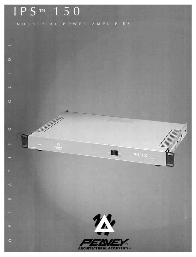
Peavey IPS 150 User manual

Peavey
Peavey PA 100 User manual

Peavey
Peavey IP 1.3K User manual

Peavey
Peavey 6534 User manual

Peavey
Peavey Supreme 160 User manual

Peavey
Peavey Special User manual

Peavey
Peavey Escort 6000 User manual

Peavey
Peavey IPR2 5000 DSP User manual

Peavey
Peavey CS 800X User manual

Peavey
Peavey Mark V M-3000 User manual

Peavey
Peavey TNT 130 User manual

Peavey
Peavey IPA 300 User manual

Peavey
Peavey KB/A 60 User manual

Peavey
Peavey IP 1 User manual

Peavey
Peavey IPR 1600 User manual

Peavey
Peavey CS 4000 User manual