Peavey Triple XXX User manual

Operating Guide

Intended to alert the user to the presence of uninsulated “dangerous voltage” within the product’s
enclosure that may be of sufficient magnitude to constitute a risk of electric shock to persons.
Intended to alert the user of the presence of important operating and maintenance (servicing)
instructions in the literature accompanying the product.
CAUTION: Risk of electrical shock — DO NOT OPEN!
CAUTION: To reduce the risk of electric shock, do not remove cover. No user serviceable parts inside. Refer
servicing to qualified service personnel.
WARNING: To prevent electrical shock or fire hazard, do not expose this appliance to rain or moisture. Before
using this appliance, read the operating guide for further warnings.
Este símbolo tiene el propósito, de alertar al usuario de la presencia de “(voltaje) peligroso” sin ais-
lamiento dentro de la caja del producto y que puede tener una magnitud suficiente como para constituir
riesgo de descarga eléctrica.
Este símbolo tiene el propósito de alertar al usario de la presencia de instruccones importantes sobre la
operación y mantenimiento en la información que viene con el producto.
PRECAUCION: Riesgo de descarga eléctrica ¡NO ABRIR!
PRECAUCION: Para disminuír el riesgo de descarga eléctrica, no abra la cubierta. No hay piezas útiles dentro.
Deje todo mantenimiento en manos del personal técnico cualificado.
ADVERTENCIA: Para evitar descargas eléctricas o peligro de incendio, no deje expuesto a la lluvia o humedad
este aparato Antes de usar este aparato, Iea más advertencias en la guía de operación.
Ce symbole est utilisé dans ce manuel pour indiquer à l’utilisateur la présence d’une tension dangereuse
pouvant être d’amplitude suffisante pour constituer un risque de choc électrique.
Ce symbole est utilisé dans ce manuel pour indiquer à l’utilisateur qu’il ou qu’elle trouvera d’importantes
instructions concernant l’utilisation et l’entretien de l’appareil dans le paragraphe signalé.
ATTENTION: Risques de choc électrique — NE PAS OUVRIR!
ATTENTION: Afin de réduire le risque de choc électrique, ne pas enlever le couvercle. Il ne se trouve à l’intérieur
aucune pièce pouvant être reparée par l’utilisateur. Confiez I’entretien et la réparation de l’appareil à un réparateur
Peavey agréé.
AVERTISSEMENT: Afin de prévenir les risques de décharge électrique ou de feu, n’exposez pas cet appareil à la
pluie ou à l’humidité. Avant d’utiliser cet appareil, lisez attentivement les avertissements supplémentaires de ce
manuel.
Dieses Symbol soll den Anwender vor unisolierten gefährlichen Spannungen innerhalb des Gehäuses
warnen, die von Ausreichender Stärke sind, um einen elektrischen Schlag verursachen zu können.
Dieses Symbol soll den Benutzer auf wichtige Instruktionen in der Bedienungsanleitung aufmerksam
machen, die Handhabung und Wartung des Produkts betreffen.
VORSICHT: Risiko — Elektrischer Schlag! Nicht öffnen!
VORSICHT: Um das Risiko eines elektrischen Schlages zu vermeiden, nicht die Abdeckung enfernen. Es befinden
sich keine Teile darin, die vom Anwender repariert werden könnten. Reparaturen nur von qualifiziertem
Fachpersonal durchführen lassen.
ACHTUNG: Um einen elektrischen Schlag oder Feuergefahr zu vermeiden, sollte dieses Gerät nicht dem Regen
oder Feuchtigkeit ausgesetzt werden. Vor Inbetriebnahme unbedingt die Bedienungsanleitung lesen.
2

As hot as the name implies, this newest member of the Ultra™Tube Series rips. From its high-gain
input to paralleled speaker output jacks, the Peavey Electronics Triple XXX is not for the faint of
heart. Engineered for today’s discriminating guitarist, this amplifier is loaded with practical features
useful in real-world applications. Delivering an earth-quaking 120 Watts of pure tube power, the
Triple XXX is easily controllable thanks to a master volume pot, as well as independent volume
controls for each of its three channels. The Ultra and Crunch channels also have gain controls to
further assist in taming this beast while achieving killer sound. Tone contour is accomplished through
passive controls for Bass, Mid, and Treble on the Clean channel, while the Ultra and Crunch
channels utilize Peavey’s exclusive Bottom, Body, and Hair active controls. Designed to work
equally well into 4, 8, or 16-Ohm loads, matching this monster to a cabinet is limited only by your
imagination. With footswitchable channel and effects loop, the Triple XXX lets you keep your hands
on the guitar - and your eyes on your dream.
FEATURES
• Three 12AX7 preamp tubes
• Four 6L6GC power amp tubes driven by a 12AX7
• Power amp convertible to use four EL34 tubes
• Footswitchable effects loop with independent send and return controls
• Damping switch (Tight, Medium, Loose)
• Special noise gate circuitry on Ultra and Crunch channels
• Line out with level control
• Cabinet impedance switch (4, 8, or 16 Ohms)
• Heavy-duty power, standby and channel select toggle switches
• Classic power status indicator lamp
• Chrome-plated brass control knobs
3
ENGLISH

(1) POWER SWITCH
This two-way toggle switch applies mains power to the unit. The red POWER STATUS LAMP
(3) will illuminate when this switch is in the ON position.
(2) STANDBY SWITCH
This two-way toggle switch allows the amp to be placed in the STANDBY mode. In the
STANDBY position the tubes stay hot but the amplifier is not operational. Switching to the ON
position places the amp in active mode.
(3) POWER STATUS LAMP
This indicator illuminates when mains power is being supplied to the amp.
(4) MASTER VOLUME
This control sets the overall volume level of the amp. Once the desired balance between the
three channels in the amplifier has been achieved, the entire output level of the unit can be
increased or decreased by rotating this control. Clockwise rotation increases level;
counterclockwise rotation decreases level.
(5) HAIR
This control, on both the Ultra and Crunch channels, varies the high frequency response of
the amplifier. It is an active control (shelving type) and allows 15 dB of boost or cut.
(6) BODY
This control, on both the Ultra and Crunch channels, varies the mid frequency response of
the amplifier. It is an active control (peak/notch type) and allows 15 dB of boost or cut.
(7) BOTTOM
This control, on both the Ultra and Crunch channels, varies the low frequency response of the
amplifier. It is an active control (shelving type) and allows 15 dB of boost or cut.
(8) VOLUME
This control, on all three channels, sets the overall level of its respective channel.
FRONT PANEL
1 2 43 65 87 9 11 12 13 14 15
10
8
4

(9) GAIN
This control, on both the Ultra and Crunch channels, controls the input volume level of the
channel. Rotating this control clockwise will increase the amount of preamp distortion and
sustain.
(10) CHANNEL ACTIVATION LEDs
These indicators signify which channel is active. Ultra channel activation illuminates the red
LED; Crunch channel activation illuminates the yellow LED; and Clean channel activation
illuminates the green LED.
(11) TREBLE
This passive control regulates the high frequencies for the Clean channel.
(12) MID
This passive control regulates the mid frequencies for the Clean channel.
(13) BASS
This passive control regulates the low frequencies for the Clean channel.
(14) INPUT
This 1/4" jack is designed to accommodate most any guitar output signal. Input signal gain
can be adjusted by the GAIN (9) controls (Ultra and Crunch channels only).
(15) CHANNEL SELECT SWITCH
This three-position toggle switch allows selection between the amplifier’s three channels. LED
(10) illumination indicates which channel is active. Channel switching can also be
accomplished by footswitch. See the FOOTSWITCH section of this manual for explanation of
switch operation. The CHANNEL SELECT SWITCH must be set in the Ultra position in order
for the footswitch to operate properly.
5

(16) EFFECTS SEND LEVEL
This calibrated (0 – 10) control sets the level of signal being sent to external effects and/or
signal processors. Clockwise rotation increases the amount of signal being sent;
counterclockwise rotation decreases the amount. For the quietest operation, the EFFECTS
SEND LEVEL should be set as high as possible. Generally, the SEND and RETURN levels
should be set oppositely. If the EFFECTS SEND LEVEL is set low, the EFFECTS RETURN
LEVEL (19) is set high to achieve unity gain. If volume boost is desired, turn both controls to
higher settings.
(17/18) EFFECTS SEND / EFFECTS RETURN
These 1/4" mono (TS) jacks allow signal to be sent to and returned from external effects
and/or signal processors. Using shielded cables with 1/4" mono (TS) phone plugs, patch from
EFFECTS SEND to the input of the external device, and from the output of the external
device to EFFECTS RETURN. Only devices that do not increase signal gain should be used
in this effects loop (chorus, delay, reverb, etc.). If the footswitch is used, the EFFECTS
SELECTOR (33) switch must be depressed to activate the effects loop. See the
FOOTSWITCH section of this manual for explanation of switch operation.
(19) EFFECTS RETURN LEVEL
This calibrated (0 – 10) control sets the level of signal being returned from external effects
and/or signal processors. Clockwise rotation increases the amount of signal being returned;
counterclockwise rotation decreases the amount. Again, SEND and RETURN levels should
be set oppositely, with the SEND level being high and the RETURN level low to ensure the
quietest operation.
(20) REMOTE SWITCH
This seven-pin DIN connector is provided for the connection of the remote footswitch. The
footswitch cable should be connected before the amp is powered up. See the FOOTSWITCH
section of this manual for explanation of switch operation.
(21) BIAS TEST TERMINALS
These terminals are provided to measure the bias of the amplifier’s power tubes. A knob
behind the back panel grill allows for adjustment. Bias adjustment should only be done by a
qualified technician.
(22) DAMPING SWITCH
This three-position switch allows adjustment of the amplifier’s damping factor. Damping is the
REAR PANEL
16 17 18 19 20 21 22 23 2524 26 28 29
27
6

ability of an amplifier to control speaker cone motion after a signal disappears. A high
damping factor (TIGHT) reduces cone vibration quicker than a low (LOOSE) factor. This
switch works much like the resonance and presence controls on other Peavey amps, if those
controls were turned simultaneously. If the DAMPING SWITCH is changed, the volume of the
amp will also change and require re-adjustment.
(23) CABINET IMPEDANCE SWITCH
This three-position switch allows appropriate selection of speaker cabinet impedance. If two
enclosures of equal impedance are used, the switch should be set to half the individual value.
For example, two 16-Ohm enclosures necessitate an 8-Ohm setting, while two 8-Ohm
enclosures would require a 4-Ohm setting. Minimum speaker impedance is 4 Ohms.
(24) SPEAKER OUTPUTS
These paralleled 1/4" mono (TS) jacks are provided for the connection of speaker
enclosure(s). Again, minimum speaker impedance is 4 Ohms. The CABINET IMPEDANCE
SWITCH (23) should be set to match the load of the speaker cabinet(s).
(25) LINE OUT LEVEL
This control sets the level of signal being sent out of the LINE OUT (26) jack. It may be used
to balance the level of slave power amp/speaker systems driven from the LINE OUT (26) to
the level of cabinets driven from the SPEAKER OUTPUTS (24).
(26) LINE OUT
This 1/4" mono (TS) jack provides a post-power amp signal to drive another power
amp/speaker system while maintaining the amplifier’s tone.
(27) FUSE
A fuse is located within the cap of the fuse holder. This fuse must be replaced with one of the
same type and value to avoid damaging the amplifier and voiding the warranty. If the amp
repeatedly blows the fuse, it should be taken to a qualified service center for repair.
WARNING: THE FUSE SHOULD ONLY BE REPLACED AFTER THE POWER CORD HAS
BEEN DISCONNECTED.
(28) GROUND POLARITY SWITCH
This three-position, rocker-type switch should normally be placed in the center (0) position. If
hum or noise is noticed coming from the speaker enclosure(s), the switch may be placed in
the “+” or “-” position to minimize hum/noise. If changing the polarity does not alleviate the
problem, consult your authorized Peavey dealer, the Peavey factory, or a qualified service
technician.
(29) IEC MAINS CONNECTOR
This is a standard IEC power connector. An AC mains cord having the appropriate AC plug
and ratings for the intended operating voltage is included in the carton. The mains cord
should be connected to the amplifier before connecting to a suitable AC outlet.
U.S DOMESTIC AC MAINS CORD
The mains cord supplied with the unit is a heavy-duty, 3-conductor type with a conventional
120 VAC plug with ground pin. If the outlet used does not have a ground pin, a suitable
grounding adapter should be used, and the third wire should be grounded properly.
Never break off the ground pin on any equipment. It is provided for your safety.
7

(30) CABLE CONNECTOR
This 7-pin DIN connector is provided for connecting the footswitch to the amplifier REMOTE
SWITCH (20) via the cable included in the carton. Connections at the switch and the amplifier
should be made before the amp is powered up.
(31) ULTRA / CRUNCH SELECTOR
This switch selects between the Ultra and Crunch channels on the amplifier. The adjacent
LED will illuminate when the Ultra channel is selected. When the LED is dark, the Crunch
channel is selected. The CLEAN SELECTOR (32) must be in the BYPASS mode to activate
either the Ultra or Crunch channel.
(32) CLEAN SELECTOR
This switch selects the Clean channel and will activate regardless of the position of the
ULTRA / CRUNCH SELECTOR (31). The adjacent LED will illuminate when the Clean
channel is selected. This switch must be in the BYPASS position, indicated by a dark LED, in
order to utilize the ULTRA / CRUNCH SELECTOR (31).
(33) EFFECTS SELECTOR
This switch activates the amplifier’s effects loop (16 – 19). The adjacent LED will illuminate
when the effects loop is active.
FOOTSWITCH 30
8
NOTE: FOR UK ONLY
If the colors of the wires in the mains lead of this unit do not correspond with the colored markings
identifying the terminals in your plug, proceed as follows: (1) The wire that is colored green and
yellow must be connected to the terminal that is marked by the letter E, the earth symbol, colored
green, or colored green and yellow. (2) The wire that is colored blue must be connected to the
terminal that is marked with the letter N or the color black. (3) The wire that is colored brown must
be connected to the terminal that is marked with the letter L or the color red.
31 32 33

Power Amplifier Section:
Tubes:
Four 6L6GCs with 12AX7 driver
Rated Power and Load:
120 W RMS into 16, 8, or 4 Ohms
Power @ Clipping:
(typically @ 5% THD, 1 kHz, 120 VAC line)
120 W RMS into 16, 8, or 4 Ohms
Frequency Response:
±3 dB 50 Hz to 20 kHz @ 90 W RMS into 8 Ohms
Hum and Noise:
Greater than 76 dB below rated power
Power Consumption:
Domestic: 400 W, 50/60 Hz, 120 VAC
Export: 400 W, 60 Hz, 220-230/240 VAC
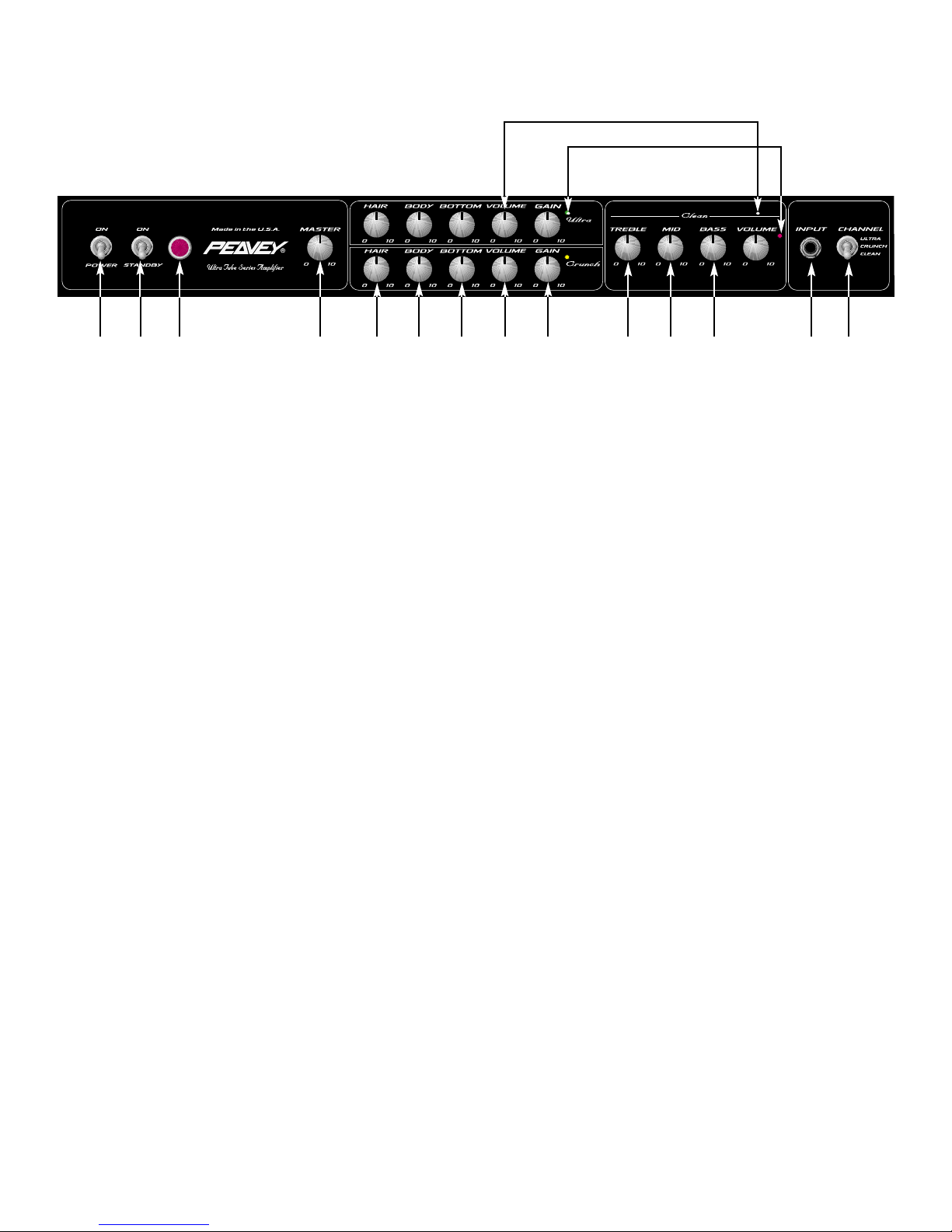
Preamp Section:
Tubes:
Three 12AX7s
The following specs are measured @ 1 kHz with the controls
preset as follows:
Low and High EQ @ 10, Mid EQ @ 0
Ultra and Crunch Posts @ 10
Bottom, Body, and Hair EQ @ 5
Effects Send @ 0
Effects Return @ 10
Master Level @ 5
Nominal Levels are with Pre Gain @ 5
Minimum Levels are with Pre Gain @ 10
Clean Channel:
Nominal Input Level: -20 dBV, 100 mV RMS
Minimum Input Level: -30 dBV, 30 mV RMS
Maximum Input Level: 0 dBV, 1.0 mV RMS
Crunch Channel:
Nominal Input Level: -80 dBV, 0.1 mV RMS
Minimum Input Level: -90 dBV, 0.03 mV RMS
Ultra Channel:
Nominal Input Level: -80 dBV, 0.1 mV RMS
Minimum Input Level: -90 dBV, 0.03 mV RMS
Effects Send:
Load Impedance: 47 k Ohms or greater
Minimum Output: -10 dBV, 300 mV RMS
Maximum Output: 0 dBV, 1 V RMS
Effects Return:
Impedance: High-Z, 80 k Ohms
Minimum Input Sensitivity: -10 dBV, 300 mV RMS
Maximum Input Sensitivity: 0 dBV, 1 V RMS
Line Output:
Load Impedance: 47 k Ohms or greater
Adjustable Output: ±20 dBV, 0.1 V RMS-10 V RMS
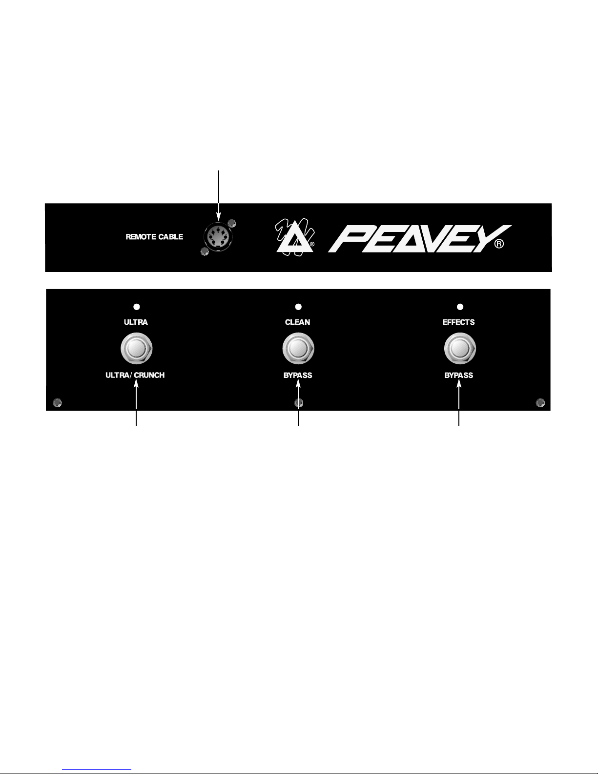
Remote Footswitch:
Special 3-button unit with LED indicators (supplied)
System Hum and Noise @ Nominal Level:
(Clean channel, 20 Hz to 20 kHz unweighted)
Greater than 74 dB below rated power
(Special noise gate circuitry for Ultra & Crunch)
Equalization: (Clean channel only)
Custom Low, Mid, and High passive type EQ
Voicing: (Ultra and Crunch channels only)
Active Bottom, Body, and Hair (Edge) EQ
Boost/Cut ±12 dB
Dimensions and Weight:
11.0" (279 mm) H x 26.5" (673 mm) W x 11.0" (279 mm) D
52 lbs. (23.6 kg)
TRIPLE XXX SPECIFICATIONS
9

10
This block diagram shows the signal path within the unit. In order to thoroughly
understand the unit's functions, please study the block diagram carefully.
TUBE
STAGE
SWITCH
LOGIC
RETURN
SEND
F.S.W
CHANNEL
ULTRA
TUBE
STAGES
SWITCH
LOGIC FX LOOP
BYPASS
EFFECTS
LOOP
VOICING
INPUT
BOT. BODY HAIR
BOT. BODY HAIR
ULTRA
CLEAN
TUBE
STAGE
CLEAN
BASS MID TREBLE
MASTER
VOLUME
TUBE
STAGES
TUBE
POWERAMP
IMPEDANCE
SWITCH
SEND
RETURN
LEVEL
LINE
OUT
CRUNCH
PRE
PRE POST
POST
CRUNCH
PRE
DAMPING
SWITCH
4Ω8Ω16Ω
Triple XXX Block Diagram

11
Como su nombre lo indi-
ca, el nuevo miembro de la serie Ultra™Tube en increíble. Desde su entrada de alta ganancia a sali-
das de parlantes en paralelo, el Triple XXX de Peavey Electronics no es para débiles del corazón.
Diseñado para el guitarrista exigente de hoy, este amplificador viene cargado de posibilidades prác-
ticas para el mundo real. Ofreciendo 120 watts de poder de bulbos, el Triple XXX es fácil de contro-
lar gracias a su perilla de volumen maestro, así como controles de volumen independientes para
cada uno de sus 3 canales. Los canales Ultra y Crunch también cuentan con controles ayudando
aun más el conseguir un sonido que mate. El control de tono se lleva a cabo por medio de controles
pasivos de Graves, Medios y Agudos en el canal limpio, mientras que los canales Ultra y Crunch
utilizan los controles activos exclusivos de Peavey Bottom (graves), Body (cuerpo) y Hair (agudos).
Diseñados para funcionar bien con impedancias de 4, 8, ó 16 ohmios, el igualarlo con parlantes se
limita sólo por tu imaginación. Con circuitos controlables por pedal de canal y efectos, el Triple XXX
te permite mantener tus manos en tu guitarra... y tus ojos en tu sueño.
CARACTERISTICAS
• Tres Bulbos de preamplificador 12AX7
• Cuatro bulbos de amplificador 6L6GC alimentados por un 12AX7
• Amplificador convertible para usar bulbos EL34
• Circuito de efectos controlable por pedal con controles independientes de envió y retorno
• Interruptor de Damping (Apretado, Medio y Suelto)
• Circuitos especiales de compuerta en los canales Ultra y Crunch
• Salida de línea con control de nivel
• interruptor de impedancia de gabinetes (4, 8, o 16 Ohmios)
• Interruptores resistentes de encendido standby y canal
• Lámpara clásica indicadora de estatus
• Perillas de control cromadas.
ESPAÑOL

12
(1) INTERRUPTRO DE PODER
Este interruptor de dos posiciones aplica corriente a la unidad. La lámpara de estatus roja (3)
se iluminará cuando el interruptor de encuentre en la posición de encendido (ON).
(2) INTERRUPTOR DE STANDBY
Este interruptor de dos posiciones permite poner al amplificador en modo STANDBY. En la
posición STANDBY los bulbos se mantienen calientes pero el amplificador no puede ser
operado. Cambiar a la posición de ON pone al amplificador en modo activo.
(3) LÁMPARA DE ESTATUS DE PODER
Este indicador se ilumina cuando el amplificador recibe corriente.
(4) VOLUMEN MAESTRO
Este control ajusta el volumen general del amplificador. Una vez que se alcanza el balance
entre los tres canales del amplificador, la salida completa del amplificador puede ser
incrementada o reducida al rotar este control. Con las manecillas del reloj el nivel se
incrementará; y contra las manecillas se reducirá.
(5) HAIR
Este control, tanto en el canal Crunch como en el Ultra, varia la respuesta de frecuencias
agudas del amplificador. Es un control activo y permite 15 dB de recorte o aumento.
(6) BODY
Este control, tanto en el canal Crunch como en el Ultra, varia la respuesta de frecuencias
medias del amplificador. Es un control activo y permite 15 dB de recorte o aumento.
(7) BOTTOM
Este control, tanto en el canal Crunch como en el Ultra, varia la respuesta de frecuencias
graves del amplificador. Es un control activo y permite 15 dB de recorte o aumento.
(8) VOLUMEN
Este control, en los tres canales, ajusta el nivel de su respectivo canal.
(9) GANANCIA
Este control, tanto en el canal Ultra como Crunch, controla el volumen de entrada del canal.
El rotar la perilla en dirección de las manecillas del reloj incrementará la cantidad de
distorsión y suspensión.
1 2 43 65 87 9 11 12 13 14 15
10
8
PANEL FRONTAL

13
(10) LEDs DE ACTIVACIÓN DE CANAL
Estos indicadores indican el canal que está activo. El canal Ultra ilumina el LED rojo, el canal
Crunch el amarillo y el canal Limpio el LED verde.
(11) TREBLE
Este control pasivo regula las frecuencias agudas del canal Limpio.
(12) MID
Este control pasivo regula las frecuencias medias del canal Limpio.
(13) BASS
Este control pasivo regula las frecuencias graves del canal Limpio.
(14) ENTRADA
Este conectador de 1/4" ha sido diseñado para funcionar con casi cualquier señal de salida
de guitarra. La ganancia de entrada puede ser ajustada por medio de los controles de
GANANACIA (9) (Canales Ultra y Crunch solamente).
(15) INTERRUPTOR DE SELECCIÓN DE CANAL
Este interruptor de tres posiciones permite la selección entre los tres canales del
amplificador. La iluminación de los LEDs (10) indica el canal que está activo. Los canales
también se pueden cambiar con pedal. Ver la sección de PEDAL en este manual para una
explicación de su uso. El INTERRUPTOR DE SELECCION DE CANAL tiene que estar en la
posición Ultra para que el pedal funcione correctamente.
(16) NIVEL DE ENVIO DE EFECTOS
Este control calibrado (0-10) ajusta el nivel de señal que se manda a una unidad externa de
efectos o procesador. La rotación en dirección de las manecillas del reloj incrementa la
cantidad de señal que se manda, contrarreloj la reduce. Para la operación más silenciosa el
NIVEL DE ENVIO DE EFECTOS debe estar lo más alto posible. Generalmente, los niveles
de ENVIO y RETORNO deben ser ajustados opuestamente. Si el NIVEL DE ENVIO DE
EFECTOS (16) es muy bajo, el NIVEL DE RETORNO DE EFECTOS debe ser alto. Si se
desea incrementar el volumen, ajusta las dos perillas altas.
(17-18) ENVIO DE EFECTOS/RETORNO DE EFECTOS
Estos conectadores mono de 1/4" permiten que la señal sea enviada y regresada de
unidades de efectos externas y/o procesadores. Con cables propiamente aislados mono de
1/4" (TS) tipo phone, conecta del ENVIO DE EFECTOS (17) a la entrada del procesador
externo, y de la salida del procesador al RETORNO DE EFECTOS (18). Sólo se deben usar
REAR FRONTAL
16 17 18 19 20 21 22 23 2524 26 28 29
27

14
procesadores que no incrementen la ganancia de la señal en este circuito (chorus, delay,
reverb, etc.). Si se usa pedalera el interruptor SELECTOR DE EFECTOS (33) debe estar
oprimido para activar el circuito de efectos. Ver la sección de PEDALERA en este manual
para más detalles de operación.
(19) NIVEL DE RETORNO DE EFECTOS
Este control calibrado (0-10) ajusta el nivel de señal que regresa de la unidad de efectos o
procesador externo. La rotación en sentido de las manecillas del reloj incrementará la
cantidad de señal que regresa; la rotación en dirección contrarreloj reducirá la cantidad. Una
vez más, los controles de ENVIO y RETORNO deben usarse de manera opuesta, con el
ENVIO alto y el RETORNO bajo para una operación más silenciosa.
(20) CONTROL REMOTO
Este conectador DIN de 7 agujas se incluye para la conexión de un pedal de control remoto.
El cable del pedal debe ser conectado antes que el amplificador sea encendido. Ver la
sección de PEDALERA en este manual para más detalles de operación.
(21) TERMINALES DE PRUEBA DE BIAS
Estas terminales se incluyen para medir el bias de los bulbos del amplificador. Una perilla
detrás de la parrilla trasera permite su ajuste. El ajuste del bias sólo debe llevarse a cabo por
un técnico calificado.
(22) INTERRUPTOR DE DAMPING
Este interruptor de tres posiciones permite ajustar el factor de damping del amplificador.
Damping es la habilidad del amplificador de controlar el cono del parlante una vez que la
señal ha desaparecido. Un factor de damping elevado (ajustado) reduce la vibración del cono
más rápido que un factor bajo (suelto). Este interruptor funciona similar a los controles de
resonancia y presencia de otros amplificadores Peavey, si esos controles fueran subidos
simultáneamente.. Si el INTERRUPTOR DE DAMPING es cambiado, el volumen del
amplificador también cambiará y requerirá ajustes.
(23) INTERRUPTOR DE IMPEDANCIA DE GABINTES
Este interruptor de tres posiciones permite seleccionar la impedancia del gabinete de
parlantes. Si se usan dos gabinetes de distintas impedancias, el interruptor debe estar en la
mitad de su valor individual. Por ejemplo, dos parlantes de 16 ohmios necesitan una posición
de 8 ohmios, mientras que dos parlantes de 8 ohmios necesitan la posición de 4 ohmios. La
impedancia mínima en parlantes es 4 ohmios.
(24) SALIDAS DE PARLANTES
Estos conectores paralelos de 1/4" (TS) se proveen para las conexiones de los parlantes.
Una vez más, la impedancia mínima en parlantes es de 4 ohmios. EL INTERRUPTOR DE
IMPEDANCIA DE GABINTES (23) debe estar de acuerdo con la capacidad de los gabinetes.
(25) NIVEL DE SALIDA DE LINEA
Este control ajusta en nivel de la señal que es mandada por el conector de SALIDA DE
LINEA (26). Puede ser usado para balancear el nivel de poder esclavo de sistemas de
amps/parlantes alimentados por la SALIDA DE LINEA (26) al nivel de gabinetes alimentados
de las SALIDAS DE PARLANTES(24).

15
(26) SALIDA DE LINEA
Este conector de 1/4" (TS) provee una señal post-amplificador para alimentar otro
amplificador/parlante manteniendo el tono del amplificador.
(27) FUSIBLE
Un fusible se localiza dentro de la tapa de fusible. Este fusible tiene que ser reemplazado
con uno del mismo tipo y valor para no dañar el amplificador y cancelar la garantía. Si el
amplificador continuamente vuela el fusible, debe ser llevado a un centro de servicio
calificado para su reparación.. CUIDADO: EL FUSIBLE SÓLO DEBE SER CAMBIADO UNA
VEZ QUE EL CABLE DE CORRIENTE HA SIDO DESCONECTADO.
(28) INTERRUPTOR DE POLARIDAD DE TIERRA
Este interruptor de tres posiciones por lo general debe encontrarse en la posición central (0).
Si se escucha hum o ruido de los parlantes, el interruptor puede cambiarse a las posiciones
(+) o (-) para minimizar el ruido. Si el cambio de polaridad no resuelve el problema, consulte
a su distribuidor Peavey autorizado, la fabrica de Peavey o a un técnico capacitado.
(29) CONECTADOR PRINCIPAL IEC
Este es un conectador estándar IEC. Un cable de CA con los conectores y capacidades para
el voltaje de operación es incluido en el paquete. El cable de corriente debe ser conectado al
amplificador antes de conectarse a la fuente de corriente.
CABLE DE CORRIENTE DOMESTICO EN EEUU
El cable de corriente incluido con la unidad es uno de 3 vías con conectador convencional de
120 VAC y aguja de tierra. Si la fuente no cuenta con entrada de tierra, un adaptador debe
ser usado y la tercera aguja debe ser aterrizada correctamente.
Nunca se rompa la aguja de tierra en ningún equipo. Esta está ahí por tu seguridad.
NOTA: REINO UNIDO SOLAMENTE

16
(30) CONECTOR DE CABLE
Este conector tipo DIN de 7 agujas se provee para conectar una pedalera en el CONTROL
REMOTO (20) vía el cable incluido en el paquete. Las conexiones de la pedalera y
amplificador deben llevarse a cabo antes de encenderlo.
(31) SELECTOR ULTRA / CRUNCH
Este interruptor selecciona entre los canales Ultra y Crunch del amplificador. El LED
adyacente se iluminará cuando el canal es seleccionado. Cuando el LED no esté encendido,
el canal Crunch está seleccionado. El SELECTOR LIMPIO (32) tiene que estar en posición
BYPASS para activar el canal Ultra o Crunch.
(32) SELECTOR LIMPIO
Este interruptor selecciona el canal limpio y es activado amén de la posición del SELECTOR
ULTRA / CRUNCH (31). El LED adyacente se iluminará cuando el canal limpio es
seleccionado. Este interruptor tiene que estar en la posición BYPASS, indicado por el LED
oscuro, para utilizar los canales el SELECTOR ULTRA / CRUNCH (31).
(33) SELECTOR DE EFECTOS
Este interruptor activa el circuito de efectos del amplificador (16-19). El LED adyacente se
iluminará cuando el circuito de efectos esté activo
FOOTSWITCH 30
31 32 33

17
Sección del Amplificador de Poder:
Bulbos:
Cuatro 6L6GCs con driver 12AX7
Poder medido y carga:
120 W RMS a 16, 8, o 4 Ohmios
Capacidad @ Clipping:
(Típicamente @ 5% THD, 1 kHz, línea de CA de 120 V)
120 W RMS a 16, 8, o 4 Ohmios
Respuesta de frecuencias:
±3 dB 50 Hz a 20 kHz @ 90 W RMS a 8 Ohmios
Hum y ruido:
Más de 76 dB bajo poder medido
Consumo de poder:
Domestico: 400 W, 50/60 Hz, 120 V CA
Exportación: 400 W, 60 Hz, 220-230/240 V CA
Sección de preamplificador:
Bulbos:
Tres 12AX7s
Las siguientes especificaciones medidas @ 1 kHz con
controles de la siguiente manera:
EQ Grave y Agudo @ 10, EQ Medio @ 0
Ultra y Crunch @ 10
EQ Bottom, Body, y Hair @ 5
envió de Efectos @ 0
Retorno de Efectos @ 10
Nivel Maestro @ 5
Niveles nominales con Pre Ganancia @ 5
Niveles mínimos con Pre Ganancia @ 10
Canal Limpio:
Nivel de Entrada Nominal: -20 dBV, 100 mV RMS
Nivel de Entrada Mínimo: -30 dBV, 30 mV RMS
Nivel de Entrada Máximo: 0 dBV, 1.0 mV RMS
Canal Crunch:
Nivel de Entrada Nominal: -80 dBV, 0.1 mV RMS
Nivel de Entrada Mínimo: -90 dBV, 0.03 mV RMS
Canal Ultra:
Nivel de Entrada Nominal: -80 dBV, 0.1 mV RMS
Nivel de Entrada Mínimo: -90 dBV, 0.03 mV RMS
envió de Efectos:
Impedancia: 47 k Ohmios o más
Salida Mínima: -10 dBV, 300 mV RMS
Salida Máxima: 0 dBV, 1 V RMS
Retorno de Efectos:
Impedancia: High-Z, 80 k Ohmios
Sensibilidad de Entrada Mínima: -10 dBV, 300 mV RMS
Sensibilidad de Entrada Máxima: 0 dBV, 1 V RMS
Salida de Línea:
Impedancia: 47 k Ohmios o más
Salida Ajustable: ±20 dBV, 0.1V RMS-10 V RMS
Pedalera de Control Remoto:
Unidad Especial de tres botones con indicadores LED (incluidos)
Hum y Ruido del Sistema @ Nivel Nominal:
(Canal Limpio, 20 Hz a 20 kHz sin pesar (unweighted)
Más de 74 dB bajo el poder medido
(Circuitos especiales de compuerta para los canales Crunch y
Ultra)
Ecualización: (Canal Limpio Solamente)
Ecualizador Pasivo de Graves, Medios y Agudos
Voicing: (Canales Ultra y Crunch Solamente)
EQ de Graves activos, Cuerpo (Body), y Hair (Edge)
Incremento/Recorte ±12 dB
Dimensiones y peso:
11.0" (279 mm) A x 26.5" (673 mm) A x 11.0" (279 mm) P
52 lbs. (23.6 Kg.)
TRIPLE XXX ESPECIFICACIONES.

18
FRANÇAIS
Félicitations pour votre achat Peavey! Comme son nom l’indique, la Triple XXX est un produit
énorme tant en terme de puissance, de polyvalence, de qualité sonore et de fabrication. Etudiée
pour satisfaire même les guitaristes les plus intransigeants, elle représente un aboutissement dans
le mariage de la lampe et la technologie moderne. 120 Watts de puissance “tout lampes” acceptant
les deux standards 6L6 et EL-34, équalisations active et passive, préampli équippé de 12AX7, sortie
ligne et boucle d’effets permettent au Triple XXX de proposer une solution à tous types de
guitaristes, à un prix défiant toute concurrence.
CARACTERISTIQUES
• Trois lampes 12AX7 de pré-amplification, une pour l’amplification
• Quatre lampes 6L6GC pour l’amplification
• Possibilité d’utiliser quatre lampes EL34 pour l’amplification
• Boucle d’effets activable au pied à niveaux d’entrée et de sortie indépendants
• Interrupteur d’”amortisement” (Damping switch) à trois positions (tight, medium, loose)
• Circuit spécial de suppression de bruit (noise gate) sur les canaux Ultra et Crunch
• Contrôle de niveau ligne (Line out)
• Sélecteur d’impédance de cabinet de hauts-parleurs (4, 8, et 16 Ohms)
• Interrupteur renforcé pour l’alimentation, le circuit de chauffe des lampes et la sélection de canal
• Indicateurs de statut à lampes classiques (Très visibles)
• Boutons de contrôle chromés

19
(1) SELECTEUR D’ALIMENTATION
Cet interrupteur 2-positions contrôle l’alimentation électrique pour votre unité. Une lampe de
statut (3) s’illumine lorsque l’unité est sous tension.
(2) SELECTEUR DE CIRCUIT DE CHAUFFE (STANDBY)
Cet interrupteur 2-positions permet à votre unité d’alimenter les lampes sans les rendre
opérationnelles (aucun signal en sortie). En position STANDBY, les lampes sont alimentées
pour leur permettre de monter (ou de rester) en température mais votre unité n’est pas
opérationelle. Passez en position ON pour mettre votre unité en mode de fonctionnement.
(3) LAMPE DE STATUT
Cette indicateur s’illumine lorsque votre unité est mise sous tension.
(4) MASTER VOLUME
Ce contrôle permet de rélgler le niveau de sortie général de votre unité. Un fois que la
balance entre les différents volumes des différents canaux vous satisfait, vous pouvez utilisez
ce contrôle pour monter ou descendre le niveau général des 3 canaux.
(5) HAIR
Ce contrôle, sur les canaux Ultra et Crunch, permet de modifier la réponse en hautes
fréquences de votre unité sur ces canaux. Ce contrôle est actif et vous permet jusqu’à 15 dB
de modification (boost ou cut).
(6) BODY
Ce contrôle, sur les canaux Ultra et Crunch, permet de modifier la réponse en fréquences
mediums de votre unité sur ces canaux. Ce contrôle est actif et vous permet jusqu’à 15 dB
de modification (boost ou cut).
(7) BOTTOM
Ce contrôle, sur les canaux Ultra et Crunch, permet de modifier la réponse en basses
fréquences de votre unité sur ces canaux. Ce contrôle est actif et vous permet jusqu’à 15 dB
de modification (boost ou cut).
(8) VOLUME
Ce contrôle, sur chacun des canaux, permet de régler le niveau du canal concerné.
1 2 43 65 87 9 11 12 13 14 15
10
8
PANNEAU AVANT

20
(9) GAIN
Ce contrôle, sur les canaux Ultra et Crunch, vous permet de déterminer le niveau du signal
d’entrée dans le canal correspondant. Tournez ce contrôle horairement pour augmenter le
niveau de saturation.
(10) LEDS D’INDICATION DE CANAL ACTIF
Ces Leds vous indique quel canal est actif. Le canal Ultra active la Led rouge, le canal
Crunch active la Led jaune et le canal clair la Led verte.
(11) TREBLE
Ce contrôle passif vous permet de filtrer les fréquences aigues du canal clair.
(12) MID
Ce contrôle passif vous permet de filtrer les fréquences medium du canal clair.
(13) BASS
Ce contrôle passif vous permet de filtrer les fréquences graves du canal clair.
(14) ENTREE (INPUT)
Ce jack 1/4" est prévu pour recevoir tous types de signaux de sortie de guitare. L’ajustement
du niveau d’entrée peut être effectué par les contrôles de GAIN (9) sur les canaux Crunch et
Ultra seulement.
(15) SELECTEUR DE CANAL
Ce selecteur 3-positions vous permet de sélectionner un des 3 canaux de votre unité. Les
Leds d’indication de canal actif(10) vous signale lequel est actuellement actif. La sélection de
canal peut également être controlée par le pédalier (fourni). Reportez-vous à la section
PEDALIER de ce manuel pour plus d’informations sur ce sujet. Le sélecteur de canal (15)
doit être en position Ultra pour que le pédalier fonctionne correctement.
(16) CONTROLE DE NIVEAU D’ENVOI D’EFFETS (EFFECTS SEND LEVEL)
Ce contrôle calibré (0 –10) détermine le niveau du signal envoyé par la sortie EFFECTS
SEND(17) à une unité externe d’effets ou autre (Pédale de volume,...). Le tourner
horairement augmentera ce niveau et vice-versa. Sa position est déterminée par la sensibilité
de l’unité externe en question.
PANNEAU ARRIERE
16 17 18 19 20 21 22 23 2524 26 28 29
27
Table of contents
Languages:
Other Peavey Amplifier manuals

Peavey
Peavey JSX 212 User manual

Peavey
Peavey SA 4200 User manual

Peavey
Peavey MMA8752 User manual

Peavey
Peavey CS 200X User manual

Peavey
Peavey 6505 Plus 112 User manual

Peavey
Peavey Rage User manual

Peavey
Peavey IP 8.5C User manual

Peavey
Peavey UA 35T II User manual

Peavey
Peavey Bandit 112 User manual

Peavey
Peavey KB 300 User manual

Peavey
Peavey 6534 User manual

Peavey
Peavey IA 10/4 User manual

Peavey
Peavey IPR 1600 User manual

Peavey
Peavey Ultra User manual

Peavey
Peavey Supreme XL User manual

Peavey
Peavey CS 3000G User manual

Peavey
Peavey TransTube Series User manual

Peavey
Peavey Ecoustic Series User manual

Peavey
Peavey IRM 8150 User manual

Peavey
Peavey PXR 1506 User manual