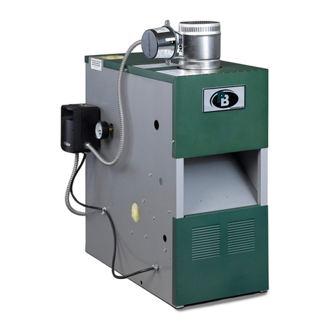
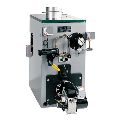
INSTALLATIONINSTRUCTIONS-SERIESWBVandWV
Readcarefullybeforebeginningwork.Itwillsavetime.Studytheincludeddrawings.
Theequipmentshallbeinstalledinaccordancewiththoseinstallationregulationsin forceinthe localareawherethe installationistobemade,including
the currenteditionof NFPA-31.Theseshallbecarefullyfollowedinall cases.Authoritieshavingjurisdictionshallbeconsultedbeforeinstallationsare
made.
Theboilermustbe installedbyaqualifiedcontractor.
Theboiler warrantycanbe voidedifthe boileris notinstalled,maintainedandservicedcorrectly.
A-ACCESSIBILITYCLEARANCES
1- Toprovidefor reasonableconditionsofaccessibility,thefollowingminimumclearancesarerecommended.
a. TopOutletFlue:At least24" in thefront,rear andon bothsides.
b. RearOutletFlue:At least24" infrontand bothsides;at least30" inthe rear.
B-AIRFORCOMBUSTIONANDVENTILATION
1-Becertainadequatefacilitiesareavailableto provideairforsatisfactorycombustionandventilation.
2 -Appliances Locatedin UnconfinedSpaces.
a. Forinstallationsin unconfinedspaceswith conventionalconstructionand largerareassuchas basements,the supplyof airfor combustionand
ventilationcan usuallybe consideredadequate.
3 - AppliancesLocatedin ConfinedSpaces.
a. If all airfor combustionandventilationisto come fromwithinthe building:two openings,one nearthe ceilingandone nearthe floorofthe boiler
roomshallbe providedwiththe minimumfree areaofeachopeningequalto 140sq.in.pergallonof oilburned.
b. If allairfor combustionandventilationisto comefromoutsidethe building:twoopenings,onenearthe ceilingandonenearthefloorofthe boiler
roomshallbeprovidedwith the minimumfreeareaof eachopeningequalto 35 sq.in.pergallonofoil burned.
If ductsareusedto conveytheair,areasof 35 sq.in.pergallon ofoil burnedforverticalductsor 70 sq.in.pergallonof oil burnedforhorizontal
ductsaretobe provided.Ductsshallhavethesameareaasthe freeareaof theopeningsto whichtheyareconnected.
C-SETTINGTHE BOILER
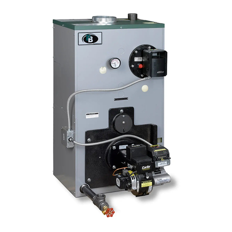
1-TheWBV/WVBoilerSectionsareFactoryAssembledwiththeTargetWallShippedinplace.Providealevelfoundation,locatedascloseaspossibleto
the center ofthe heatingsystemand tothe chimney.TheWBV/WVSeriesis availableas a completepackage,or in a knockeddownform. Referto
page5 forexplodedviewof boilerif on-the-jobassemblyisrequired.
2-This boileris suitablefor useon combustibleflooring,providedtheboilerisnot setoncarpetand ametaldrippan isplacedunderthe appliance.
3- TheWBV-03andWBV-04boilermodelsmaybe installedasa rearflueoutletunitoratopflue outletunit.This maybedonebymountingthe FlueCollar
Adapter(Item14)to eithertherear boilersectionforarearflueapplication,orto the FlueCollectorCoverPlate(Item11)foratopflueapplication.The
RearOutletCoverPlate(Item13) isthenusedto closetheremainingopening.OnPackagedUnitsthe largeknockoutintheTopJacketPanelmustbe
removedtoconverttoa topflue application.NOTE:TheWV-05boilermodelisonlyavailableas atop flueoutletunit.
4-Opentrim carton.RemoveFlueCollectorCoverPlateand BlanketSeal(Items10 and 11)and attachwith thefour (4)5/16" x 1_/2"studs,nutsand
washersprovided.Attacheitherthe FlueCollarAdapter(Item14)or the OutletCoverPlate(Item 13)to the FlueCollectorCoverPlatewiththe nuts
and washersprovidedmakingsurethe ropeseal(Item12)is in place.Attachthe remainingFlueCollaror CoverPlatetothe rearsectionwithfour(4)
5/r6"boltsandwashers.
5-Ifatanklesscoilisused,(Item9)installas pictured.WaterBoiler- frontsectionopening.SteamBoiler- rearsectionopening.Forsuggestedpipingof
tanklesswaterheatersrefertoFigures4and 5.
6 - Whenatanklesscoil is notemployed,covertheopeningwithcoverplate(Item 7 or 16).
D-JACKETASSEMBLY
1- Ifboileris tobe installedwitharear flueoutlet,removethesquareknock-outin the backpanelthenattachtobosseson middleof backsectionwith
two1/4" x 3/8"machinescrewsprovided.The backpanelhastwo 5/16"dia.holesclosetothe centerofthe panel.
2 - Attachboththe leftandrightsidepanelstothe backpanelandsecurewithsheetmetalscrews.
3 - RemoveBurnerMountingPlate (Item5) andmakecertainthe TargetWall (Item2) and CerafeltLineron floorofboilerin frontoftargetwall(Item3)
arefirmly in place.
4- Removethe two(2)knockoutsinthefrontjacketpanelwhichwill allowclearanceforthe hinge.Placethefrontjacketpanelonthe blockandattachthe
leftandrightsidepanelsin the samemanneras theyareattachedto thebackpanel.Attachthe CombustionChamberCoverPlate.
5- ReinstallCombustionChamberCoverPlate.
6- If boileristo be installedwithatop flueoutlet,removetheknock-outinthe topjacketpanelthen securewith sheetmetalscrews.
