PEKO SD-1700 User manual

Drying Cabinet
Installation and Operating Manual
Drying Cabinet
Model:-
SD-1700
SD-1900
Electronic Sensor Drying
Installation and Operating Manual

Installaon and Operang Manual Page 2
THIS USER MANUAL 3
DATA PLATE DETAILS 3
ADVICE ON SAFE OPERATION 3
DESCRIPTION OF THE CABINET 4
INSTALLATION 5
UNPACKING THE CABINET 5
DOOR ALIGNMENT 5
DOOR ADJUSTMENT 6
RESTORING THE DOOR SEALING 6
GASKET
REVERSING THE DOOR OPENING 6
LOCATION AND FIXING 7
FIXING TO A WALL 7
ELECTRICAL CONNECTION 8
VENTILATION CONNECTION 9
ADDITIONAL VENTILATION NOTES 10
START UP 11
HOW TO LOAD THE WASHING 11
CONTROL PANEL 12
DRYING PROGRAMMES 12
AUTOMATIC TIME CONTROL 12
MANUAL TIME CONTROL 13
ADJUSTING THE DRYING PROGRAMMES 14
CARE 14
CLEANING 14
SERVICE AND REPLACEMENT PARTS 15
BREAKDOWNS 15
TROUBLESHOOTING 16
TECHNICAL DATA 17
ENERGY CONSUMPTION AND 17
DRYING TIMES
MANUFACTURING STANDARDS 17
ELECTRICAL DIAGRAM 17
DIMENSION DRAWING 18
CONTENTS
Peko Equipment Limited
Unit 3, Bourne End Mills
Upper Bourne End Lane
Hemel Hempstead
Herts, HP1 2UJ
Tel: +44 (0)1442 872323
www.pekodryingcabinets.co.uk
UK Distributor: PEKO Equipment Limited reserve the right to
make improvements and/ or changes to the
cabinet and to the contents of this manual.
Origination: 08/01/20

Installaon and Operang Manual Page 3
The contents of this user manual describes the functions of
the SD-1700 / 1900 drying cabinet and how it should be used.
It also includes instructions for installation and maintenance.
DATA PLATE DETAILS
Located inside the cabinet on the left hand side panel.
For Your Reference
Date of purchase:
___________________
Serial Number:
___________________
ADVICE ON SAFE OPERATION
This advice on safe operation has been compiled so that you can avoid incorrect use and unnecessary
risks of accidents, and should be read before the drying cabinet is installed and used.
CAUTION: This equipment is only intended to be used to dry textiles washed in water.
· Do not allow children to play in, on or with the
drying cabinet. Close supervision of children is
required when they are in the immediate vicinity
of the cabinet.
· If the power cable is damaged it must be
replaced immediately. To avoid danger, this
work must only be performed by the
manufacturer’s service agent or a similarly
qualified person.
· Keep the area above the cabinet—and around
the exhaust opening—clear for air circulation
and free from dust, lint and fluff. Do not use for
storage.
· Do not use heat to dry articles containing foam
rubber or similar textured rubberised materials.
Instead, use the fan-only operation.
· Do not tamper with the controls.
· Do not install or store this cabinet where it will
be exposed to weather.
· When using fabric softeners or antistatic
agents, follow the product guidelines
concerning their use.
· Do not dry articles that have been previously
cleaned in, washed, soaked or splashed with
petrol, or other flammable/ explosive
substances, as they give off vapours that could
ignite or explode.
· Check the exhaust ducting terminal grille for
any blockage or build-up of lint. This must be
cleaned regularly.
· The manufacturer accepts no liability for repairs
carried out:-
a) by unauthorised personnel
b) with the use of non-standard parts
THIS USER MANUAL
NOTE. Keep this user
manual so it is always
available for future use.

Installaon and Operang Manual Page 4
DESCRIPTION OF THE CABINET
Models SD-1700 / 1900: Supplied with an electronic controller with automatic senor drying and manual
timer control options. Three hanging rail sections are fitted equivalent to 16m length of washing line
space. Each section can slide outwards to assist the loading process. The middle and lower sections are
hinged so that when pushed back into the cabinet they can be folded back to allow longer garments to
hang freely from the upper set of rails.
Three rails are fitted to the inside door panel on both models, and are useful for hanging smaller items e.g.
gloves and socks.

Installaon and Operang Manual Page 5
Complete delivery must include:
Cabinet Complete with Fan Unit
Basic Ventilation Fitting Kit
Fixing Pack
User Manual
INSTALLATION
Assembly kit:
DOOR ALIGNMENT
Once the cabinet has been unpacked, it may be observed
that the top of the door is not parallel with the control panel
above,.
This situation arises due to the weight of the door pulling
down on one side of the cabinet. A parallel gap between
the top of the door and the control fascia panel is an
indication that the cabinet is level and in an upright
position.
NOTE. This drying cabinet is designed to be fixed to a solid wall or structure to ensure that it
is rigid and able to maintain its form. The cabinet should be located on a solid floor and the
feet adjusted to ensure that it is level and upright before fixing back to the wall.
It is not designed to be a free standing appliance.
The cabinet must be handled
carefully at all times.
RISK OF TIPPING OVER.
Check that the product has not been
damaged in transit. Any transit damage
must be reported to the dealer within 7
days.
After unpacking, check that the product is free of
faults. Damage, defects and any missing parts must
be immediately reported to the dealer.
Check that all transportation securing devices have
been removed before connecting the dryer.
Packaging materials such as plastic and polystyrene
should be kept out of the reach of children.
UNPACKING THE CABINET

Installaon and Operang Manual Page 6
INSTALLATION
DOOR ADJUSTMENT
Minor adjustments to the door can be made by small alterations to the front levelling feet after the cabinet
has been secured.
RESTORING THE DOOR SEALING GASKET
Initially the door gasket may be slightly squashed as a result of the packaging process. This will normally
restore to full flexibility with the application of the heat generated by the drying cabinet.
REVERSING THE DOOR OPENING
The door is supplied with the hinges to the right-hand side, as standard. Follow the instructions to reverse
the opening, if required.
NOTE. With care and assistance the above procedure can also be carried out with the
cabinet in the upright position, once the unit has been secured to the wall.
1. Place the packaging materi-
al on the floor to protect
the cabinet, then lay it
down with the door upper-
most.
2. Remove the pivot pin from
the lower hinge (1) and lift
off the door. Retain the
washer (3).
3. Unscrew the pivot pin from
the upper hinge (2) and re-
fix to the opposite side.
4. Turn the door upside down
and locate into the upper
hinge pin; position door on
lower hinge bracket and
plastic guide, then screw in
the lower hinge pin (1) with
the washer (3) between the
door and bracket.

Installaon and Operang Manual Page 7
INSTALLATION
The drying cabinet is only designed for
operation indoors in a dry environment at a
temperature above freezing point.
The drying cabinet should not be installed in
a location where high pressure water is used
for cleaning.
LEVELLING
The drying cabinet should stand level on a flat
surface, resting on all four feet.
FIXING TO WALL
Secure the cabinet to the wall using the screws, washers
and plastic plugs provided in the assembly kit.
1. Open the door and drill two 8 mm holes into the
wall through the two pre-drilled holes in the rear
panel of the cabinet. Ensure any hidden water
pipes or cables etc. are avoided.
2. Insert the wall plugs and, with the spacers and
washers provided, screw the cabinet back to the
wall.
WARNING !
The drying cabinet should not be used without being
screwed to a wall due to the risk of it tipping forwards.
LOCATION AND FIXING
The drying cabinet should not be installed in a
location where any doorways or safety exits are
blocked when the door is open and the hanging
rails extended.
Ensure that the cabinet is fully pushed back to the wall
behind. If there are obstacles behind the unit e.g. service or
drainage pipes, spacer battens or off-set fixing brackets (see
image below) should be used to prevent the cabinet from
tipping forwards.
An offset fixing bracket is
available as an optional
spare part.
Part no. 670001484
(A pair of 50mm off-set
brackets with 4 screws to
secure to the cabinet).

Installaon and Operang Manual Page 8
INSTALLATION
ELECTRICAL CONNECTION
The cabinet is supplied ready for connection to the power supply with a UK style 3-pin plug complete with
a 10 A fuse.
Power supply rated at 230 V single-phase 50 Hz.
The power cable is approx. 1.9 m in length.
The plug (and socket outlet) should be in an accessible position for ease of removal. An alternative
arrangement could be a socket positioned above the cabinet with a separate fused switch at worktop
height.
Check that the supply current matches that stated on the identification plate and that the mains lead is
correctly earthed according to the standards in force. We recommend that the power supply is fitted with a
residual current device (RCD).
The manufacturer cannot be held liable if the electrical connections are not carried out as prescribed in
this manual.
NOTE. If the power cable is
damaged in any way, it must
be replaced immediately.
Replacements are available
from your main supplier or
WARNING! If the plug supplied is not suitable for the
socket outlet, or if the appliance is to be connected to fixed
wiring, it should be cut from the supply cord and disposed
of immediately. If the severed plug is introduced into a
live socket outlet there is a risk of electric shock.
NOTE. Should the plug need to be replaced for any reason, the wires in the mains lead are
coloured in accordance with the following code:
Green and Yellow = Earth
Blue = Neutral
Brown = Live
The wire coloured green and yellow must be connected to the terminal marked with the letter ‘E’,
the earth symbol , or coloured green and yellow. The wire coloured blue must be connected
to the terminal marked ’N’ or coloured black. The wire coloured brown must be connected to the
terminal marked ‘L’ or coloured red. If the fuse incorporated in the plug needs to changed, then it
should be replaced with a fuse approved by ASTA to BS1362, rated at 10 A.
WARNING!
This appliance must be earthed. If in any doubt,
consult a competent person.

Installaon and Operang Manual Page 9
INSTALLATION
VENTILATION / EXTRACTION SYSTEMS
To prevent the build-up of heat and moisture within the room, it
is recommended that a ventilation system is connected to the
cabinet. This can generally be achieved by using one of the
two options detailed below.
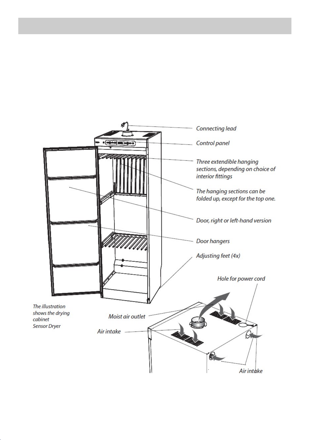
Requirements for all installations: Fit the spigot adaptor (1) to
the top of the cabinet by placing it over the cut-out and rotating
clockwise until the lugs of the spigot click into place.
The cabinet requires an optimum airflow of 95m3 per hour.
The location of the cabinet must ensure that replacement air is taken into consideration, especially in a
closet installation or where the cabinet is built-in to bespoke cupboard furniture.
1. CONNECTION TO AN EXISTING MECHANICAL SYSTEM
(Existing air conditioning / climate control system)*
This method is only suitable for buildings that have an existing
mechanical ventilation system, or where the room has a
dedicated extraction fan with a capacity of at least 95m3 /
hour. In both cases, the ducting must terminate to outside
atmosphere.
Fit the supplied white plastic ventilation adaptor (3) over the
existing wall or ceiling mounted extractor fan grille (fixing
screws for this ‘tripod’ type fitting are not supplied). This fitting
allows for both room and cabinet ventilation. Connect to the
cabinet outlet spigot with the flexible hose or other appropriate
ducting material.
*Please consult with a ventilation engineer before connecting the cabinet to a centralised building
ventilation system.
NOTE. The exhaust ducting should not be
connected into an existing chimney, boiler flue
or tumble dryer system.
2. CONNECTION TO A NATURALLY ASPIRATED SYSTEM
(Direct ducting system to outside air)
This is the preferred method of providing ventilation for the
cabinet. The ducting can be routed through an outside wall
or glazed window pane. Core cut a 105mm. diameter hole in
the outside wall, or alternatively cut a hole in a fixed pane of
window glass. Connect the flexible hose (2) to the cabinet. A
coupling fitting (4, not supplied) may be required to adapt to
the terminal fitting or ducting. Fixed open louvre fittings are
preferred complete with an integral insect mesh screen. The
ducting can also be installed with a vertical duct pipe termi-
nating on the roof.
Additional guidance notes on page 10.

Installaon and Operang Manual Page 10
INSTALLATION
ADDITIONAL GUIDANCE NOTES FOR VENTILATION DUCTING SYSTEMS
Notes:
· Standard tumble dryer back draught shutters are not suitable. Permanently open louvre or cowl fit-
tings with insect mesh screen should be used.
· The maximum effective length of ducting to outside is 3m. Keep the ducting length as short as pos-
sible with the minimum number of bends for maximum efficiency.
· Rigid metal and plastic pipe can also be used for the exhaust ducting.
· The exhaust ducting fittings supplied are standard 100mm diameter. Additional flexible hose or fit-
tings that may be required can be obtained from most builders merchants and hardware stores.
· The ducting should run in a level or vertical plane. Do not allow the ducting to fall below the top of
the cabinet. If using a longer length of flexible hose, ensure that it is supported and free from any
kinks.
· Ducting systems that are over 3m in length, or require numerous bends, may require an in-line fan
to be fitted to ensure that the moisture is extracted to outside air. An independent power supply
and switching arrangement will be required for the fan as the cabinet does not have an interface fa-
cility.
· Terminal fittings on flat or sloping roofs should extend 300mm above the roof. A traditional type
cone shaped fitting provides weathering, and also allows free access for evacuating the moist air.
· Ensure that the ducting and terminal grille are cleaned on an annual basis.
· The air intake grilles on the top panel of the cabinet must not be blocked at any time. Do not store
items on top of the cabinet.
· Do not store items on top of the cabinet.

Installaon and Operang Manual Page 11
START-UP
WARNING! Read the safety advice on
page 3 before using the drying cabinet.
1. Check that the cabinet is firmly attached to the wall. See page 7 of this manual.
2. Check that all packaging material has been removed.
3. Use a mild detergent with warm water and wash the inside and outside of the drying
cabinet. See the CARE section on page 14 of this manual.
HOW TO LOAD THE WASHING
· Hang items in the drying cabinet according to
how much space they require – not according to
their weight.
· Hang gloves, hats, scarves and similar items on
the hangers attached to the inside of the door.
· Do not overload the drying cabinet. If you do, the
washing will become creased and dry unevenly.
Instead, leave space between the garments if
possible.
· Avoid drying heavy items of clothing together
with lighter items as they have very different
drying times.
· Avoid hanging textiles that are dripping or
soaking wet, as the drying cabinet is not
intended to collect large volumes of water. This
also leads to unnecessarily long drying times.
· To avoid any potential transfer of colours, keep
light and dark/ coloured materials separate.
The SD-1700 / 1900 cabinet contains three sets of
hanging rails. Each set has 11 bars on which to
hang the washing.
· Fold back the middle and bottom sets of rails if
long garments are to be hung from the top set.
· Slide the hanging rails forward to facilitate the
loading process. Push them back when not in
use and before closing the door.
· Make sure not to hang knitted items. These will
stretch as they are heavy when wet. Instead, lay
these items flat on top of the middle or lower set
of hanging rails.
· For optimum efficiency, do not lay items flat on
the top set of hanging rails.
CAUTION! Do not dry articles that have
been previously cleaned in, washed,
soaked or splashed with petrol, or other
flammable/ explosive substances, as they
give off vapours that could ignite or
explode.
Drying tips:
· Always follow the washing machine
instructions on garment care, if they are
provided.
· If fabric softener or an antistatic product is
used, follow the manufacturer’s instructions
on their use.
· Remove washing that is already dry. This
will reduce the drying time for the remaining
items.
· Hang longer items nearest to the cabinet
walls and shorter ones towards the centre.
This allows for efficient airflow within the
cabinet and delivers the
Read this user manual before using
the drying cabinet for the first time.
This figure shows
how the air flows
within the cabinet.

Installaon and Operang Manual Page 12
CONTROL PANEL
DRYING PROGRAMMES - AUTOMATIC TIME CONTROL
NOTE. Set the temperature and time to suit the most delicate articles to be dried.
To start up automatic time control:
The drying cabinet is equipped with both automatic and manual time controls.
The cabinet is started by pressing the ON/OFF button.
By default, the cabinet will be activated with the previous programme selection. If no programme
has been selected previously, the cabinet has been without power or is completely new, the
cabinet is started in AUTO HIGH by default.
AUTO HIGH lights up and START/STOP flashes.
Selection of other automatic programmes:
If this is OK, start the cabinet by pressing START/STOP.
The LED at START/STOP stops flashing, and is lit with a steady glow.
The estimated drying time is shown on the display, where the time is counted down. After the
time has ended, the process stops automatically.
To activate the automatic drying process, press the AUTO button,
To get to the desired programme, press AUTO one or more times.
See details below for what each programme does:
Only the fan is started. This
programme is highly energy-
efficient and very gentle on the
laundry. Use this programme
when you have plenty of time
to dry your laundry. AUTO
ECO+ now lights up.
Both the fan and the element
are active, but temperature is
limited within the cabinet. Use
this programme when you
require sensitive fabrics to dry
in a shorter time. AUTO LOW
now lights up.
Both the fan and the element
are active. The temperature
restriction is significantly higher
than in AUTO LOW. This
programme dries the fabrics
quickly. AUTO HIGH now lights
up.

Installaon and Operang Manual Page 13
DRYING PROGRAMMES - AUTOMATIC TIME CONTROL
You can also select additional functions:
EXTRA DRY can be used when either AUTO LOW or AUTO HIGH is selected.
EXTRA DRY is for fabrics that are thicker and more difficult to dry such as overalls.
ski suits, etc.
ECO can be used when AUTO HIGH is selected.
ECO is a programme that utilises thermal energy so the programme is longer than
normal, but consumes less energy. If AUTO ECO+ has been chosen as a drying
programme as above, this function is already pre-selected.
DRYING PROGRAMMES - MANUAL TIME CONTROL
The cabinet is started by pressing the ON/OFF button.
By default, the cabinet will be activated with the previous programme selection. If no
programme has been selected previously, the cabinet has been without power or is completely
new, the cabinet is started in AUTO ECO+ by default (an automatic programme).
To start up manual time control:
Selection of manual programme:
To activate the manual drying process, press the MAN button,
To get to the desired programme, press MAN one or more times.
See details below for what each programme does:
Only the fan is started. This
programme is highly energy-
efficient and very gentle on the
laundry. Use this programme
when you have plenty of time
to dry your laundry. MAN
ECO+ now lights up.
Both the fan and the element
are active, but temperature is
limited within the cabinet. Use
this programme when you
require sensitive fabrics to dry
in a shorter time. MAN LOW
now lights up.
Both the fan and the element
are active. The temperature
restriction is significantly higher
than in MAN LOW. This
programme dries the fabrics
quickly. MAN HIGH now lights
up.
The display shows a standard drying time, but this can increased or decreased with
this button.
Press START/STOP. If the LED is lit, this shows that the process is under way.
The selected drying time is shown on the display. Once the time has ended, the
process stops automatically.
NOTE. Avoid opening the door when the cabinet is in operation as this will extend the drying time.
When the door is opened -P- will be displayed. The cabinet will stop heating although the fan will
continue to run. If the door remains open for 5 minutes the cabinet will then switch itself off. Closing
the door within the 5 minute period will restart the drying process. If an AUTO programme has been
interrupted the programme will start anew. If a MANUAL programme has been interrupted the
countdown will continue whilst the door is open.

Installaon and Operang Manual Page 14
ADJUSTING THE DRYING PROGRAMMES
The drying cabinet’s automatic programmes can be optimised in relation to the existing installation
conditions. This is done by adjusting the parameter values for the automatic programme concerned on
the control panel. This is only to be done if you find that:
The washing is not dried sufficiently or, The washing is over-dried.
Calibrating Sensors:
NOTE. It is important that the cabinet is at room temperature when calibrating..
To calibrate sensors, turn off the cabinet and ensure there is no load inside. Go to the parameter list,
choose parameter P400 and set it to the value 1. A calibration cycle will then start which takes around 5
minutes. When the sensors have been calibrated, the cabinet will re-start automatically.
Drying Programme Parameter
ECO+ 2165
LOW 2233
LOW EXTRA DRY 2243
HIGH 2203
HIGH EXTRA DRY 2213
HIGH ECO 2273
Parameters to Adjust:
· If you find the washing is under-dried, increase the parameter value for the relevant programme
· If you find the washing is over-dried, decrease the parameter value for the relevant programme
Please see the table below for the parameter of the programme that requires adjusting.
Access to Parameters:
· Turn the cabinet off by pressing the ON/OFF button.
· Hold down START/STOP and then press the ON/OFF
button again. Select parameter by stepping up or down
using + / -.
Adjusting Parameters:
· When the desired parameter has been selected, press
START/STOP to go to the parameter concerned.
· Adjust the parameter by stepping up or down using + / -
· Press START/STOP to leave parameter adjustment.
Leaving the Parameter List:
· When you have adjusted the parameters you want,
press MAN and START/STOP.
· If you want to reset the parameters to the factory set-
ting, press AUTO and START/STOP.
CARE
The inside and outside of the cabinet should be
cleaned with a mild soap solution and a damp
cloth.
Dust will collect on the top of the cabinet,
especially around the air intake. This can cause
operational faults within the cabinet, as well as
pose a fire hazard.
To avoid any potential problems, the top of the
cabinet should be vacuum cleaned at least once
a year, or more frequently depending on the
location of the cabinet and its application.
CLEANING
NOTE. High-pressure cleaning should not
be used.

Installaon and Operang Manual Page 15
CARE
SERVICE AND REPLACEMENTS PARTS
If the connecting cable is damaged for any
reason, it must be replaced immediately.
All genuine parts can be obtained from the drying
cabinet dealer.
NOTE. A replacement lead may only be
installed by the manufacturer, the
manufacturer’s service agent, or another
authorised electrician.
BREAKDOWNS
WARNING! Isolate the electrical supply and
remove the power plug before withdrawing
the service control unit.
The service module can be removed from the
cabinet to enable any repairs or maintenance
work to be carried out.
You MUST first disconnect the cabinet from
the power source, then open the door before
removing the five screws underneath the control
panel. Carefully pull the service module out.
Overheat Cut-Out:
The cabinet is equipped with an overheat cut-out. This trips when the temperature in the fan unit exceeds
120°C.
· When the over-heat cut out has tripped, the
display and LEDs flash. The overheat cut-
out can be reset by turning off the power
supply with the switch inside the roof of the
cabinet (see illustration).
· It is necessary to wait 10 to 15 minutes for
the temperature to fall, and for the overheat
cut-out to reclose. The power supply can
then be turned back on using the same
switch.
1. Service module
2. 5 x Torx screws

Installaon and Operang Manual Page 16
TROUBLESHOOTING
Problem What you can do
The fan does not operate and
the cabinet is not heating up:
Check that the cabinet is connected to the power supply and that
the fuses are intact. When the cabinet is switched on, there should
be a time displayed from the previous drying programme and two
LEDs should be lit.
Resonance or vibration occurs
when the fan is running:
Check that the cabinet is level in both planes and is securely fixed
to the wall. If the problem persists, try adjusting the feet ensuring
they are all in contact with the floor. See page 7 of this manual for
instructions.
The door switch is not working:
Figure shows an even gap
between the control panel
and the top of the door.
To test the switch, select a drying programme, close the door, and
press START/STOP. If the display shows - P - , open the door and
manually press the switch with your finger - the switch is found
directly beneath the control panel, to the left-hand side. If the drying
programme resumes, the door switch is functioning properly.
Check that an even gap exists between the control panel and the
top of the door. If they are not aligned properly, this may not
activate the switch. To rectify, ensure the cabinet is level and adjust
the feet and/ or door if necessary (see page 5 of this manual).
Drying is taking a long time /
does not dry:
1. Check that the correct programme has been selected for the type
of laundry.
2. Check that the laundry is not too wet (poorly spun).
3. Check that too much laundry has not been loaded into the
cabinet.
4. Adjust the parameters according to the section “Parameters to
Adjust” (Page 14)
Error Codes: If a warning or error code is shown, try and reset the controller (see
page 15).
· Er 1 - Regulator sensor. There is an error in the sensor at the
element. The error is either a discontinuity or short-circuit in the
sensor. Reset by disconnecting the power supply.
· Er 2 - Outlet sensor. Error in the sensor in the outlet duct. This
error is the same as Error 1. Reset by disconnecting the power
supply.
· Er 3 - MAX hours. The programme has not changed temperature
but has been turned off because the electronics has not received
a signal from the outlet sensor that the laundry is dry. Reset by
pressing the START/STOP button for 5 seconds.
In the event of further or persistent problems, please contact your dealer.

Installaon and Operang Manual Page 17
TECHNICAL DATA
Capacity: Up to 6.0 kg laundry (cotton)
Evaporation rate: Up to 25 g/min
Electrical connections: Single-phase 230 V, 50 / 60 Hz, 10A
Fan motor: 38 W
Heating element: 2.0 k/W
Overheat cut-out: Yes
Hanging length: 16 metres (depending on choice of interior fittings)
Dimensions: Height: 1700 / 1900 mm (plus 15 mm adjustment)
Width: 595 mm
Depth: 605 mm (overall with pull handle 630 mm)
Weight: 56 kg (1700)
60kg (1900)
Extraction rate: 95 m3 / hour
Sound level: Max 55 dB(A)
* Given values may vary depending on:
· Spin speed of washing machine
· Temperature and air humidity of room
· Air circulation in the room (supply air, exhaust air)
Programme Energy consumption
kWh/kg washing
Drying time (minutes) Temp. maximum
AUTO ECO+ 0.10 600 Room temperature
AUTO LOW 0.79 180 approx. 45°C
AUTO LOW EXTRA DRY 1.06 240 approx. 45°C
AUTO HIGH ECO 0.57 260 approx. 70°C
AUTO HIGH 0.64 85 approx. 70°C
AUTO HIGH EXTRA DRY 1.20 160 approx. 70°C
MANUFACTURING STANDARDS
See details on the drying cabinet data
plate.
WHEN DRYING SPUN WASHING*
ENERGY CONSUMPTION AND DRYING TIMES
ELECTRICAL DIAGRAM AND DIMENSION
DRAWING
The electrical wiring diagram and dimension drawing can
be obtained from the distributor (see contact details on
page 2 of this manual).
They can also be found under the ‘Downloads’ section of
the Peko Drying Cabinet website;
www.pekodryingcabinets.co.uk.

Installaon and Operang Manual Page 18
DIMENSION DRAWING

Installaon and Operang Manual Page 19

EQUIPMENT LIMITED
Unit 3, Bourne End Mills
Upper Bourne End Lane
Hemel Hempstead
Herts.
HP1 2UJ
Tel: 01442 872323 info@peko.co.uk
www.pekodryingcabinets.co.uk
This manual suits for next models
1
Table of contents
Other PEKO Dryer manuals