PEKO ETS-1700E User manual

Drying Cabinet
Installation and Operating Manual
Drying Cabinet
Model:-
ETS-1700E
Electronic Sensor Drying
Installation and Operating Manual

InstallaonandOperangManual Page2
THIS USER MANUAL 3
DATA PLATE DETAILS 3
ADVICE ON SAFE OPERATION 3
DESCRIPTION OF THE CABINET 4
INSTALLATION 4
UNPACKING THE CABINET 4
DOOR GASKET NOT SEALING 5
DOOR ADJUSTMENT 6
RESTORING THE DOOR SEALING 6
GASKET
REVERSING THE DOOR OPENING 6
LOCATION AND FIXING 7
ELECTRICAL CONNECTION 8
VENTILATION CONNECTION 9
START UP 10
HOW TO LOAD THE WASHING 10
CONTROL PANEL 11
Peko Equipment Limited
Peko House, Northbridge Road
Berkhamsted, Herts, HP4 1GE
Tel: 01442 872323
Fax: 01442 866900
UK Distributor:
DRYING PROGRAMMES 11
START THE PROGRAMME 12
STOP THE PROGRAMME 12
INTERRUPTING THE PROGRAMME 12
ADJUSTING THE DRYING PROGRAMMES 13
INTRODUCTION 13
PROCEDURE 13
CARE 14
CLEANING 14
SERVICE AND REPLACEMENT PARTS 14
TROUBLESHOOTING 14
TECHNICAL DATA 15
ENERGY CONSUMPTION AND 15
DRYING TIMES
MANUFACTURING STANDARDS 15
ELECTRICAL DIAGRAM AND 15
DIMENSIONAL DRAWING
CONTENTS

InstallaonandOperangManual Page3
The contents of this user manual describes the functions of
the ETS-1700E drying cabinet and how it should be used. It
also includes instructions for installation and maintenance.
PEKO Equipment Limited reserve the right to make
improvements and/ or changes to the cabinet and to the
contents of this manual. Origination: 03/11/17
DATA PLATE DETAILS
Located inside the cabinet on the left hand side panel.
For Your Reference
Dateofpurchase:
___________________
SerialNumber:
___________________
ADVICE ON SAFE OPERATION
This advice on safe operation has been compiled so that you can avoid incorrect use and unnecessary
risks of accidents, and should be read before the drying cabinet is installed and used.
CAUTION: This equipment is only intended to be used to dry textiles washed in water.
Do not allow children to play in, on or with the
drying cabinet. Close supervision of children is
required when they are in the immediate vicinity
of the cabinet.
If the power cable is damaged it must be
replaced immediately. To avoid danger, this
work must only be performed by the
manufacturer’s service agent or a similarly
qualified person.
Keep the area above the cabinet—and around
the exhaust opening—clear for air circulation
and free from dust, lint and fluff. Do not use for
storage.
Do not use heat to dry articles containing foam
rubber or similar textured rubberised materials.
Instead, use the fan-only operation.
Do not tamper with the controls.
Do not install or store this cabinet where it will
be exposed to weather.
When using fabric softeners or antistatic
agents, follow the product guidelines
concerning their use.
Do not dry articles that have been previously
cleaned in, washed, soaked or splashed with
petrol, or other flammable/ explosive
substances, as they give off vapours that could
ignite or explode.
Check the exhaust ducting terminal grille for
any blockage or build-up of lint. This must be
cleaned regularly.
The manufacturer accepts no liability for repairs
carried out:-
a) by unauthorised personnel
b) with the use of non-standard parts
THIS USER MANUAL
NOTE. Keep this user
manual so it is always
available for future use.

InstallaonandOperangManual Page4
DESCRIPTION OF THE CABINET
INSTALLATION
The cabinet must be handled
carefully at all times.
RISK OF TIPPING OVER.
Check that the product has not been
damaged in transit. Any transit damage
must be reported to the dealer within 7
days.
After unpacking, check that the product is free of
faults. Damage, defects and any missing parts must
be immediately reported to the dealer.
Check that all transportation securing devices have
been removed before connecting the dryer.
Packaging materials such as plastic and polystyrene
should be kept out of the reach of children.
UNPACKING THE CABINET
Complete delivery must include:
Cabinet with fan unit
Assembly kit for installing cabinet
Installation and operating manual

InstallaonandOperangManual Page5
INSTALLATION
Assembly kit:
DOOR GASKET NOT SEALING
Once the cabinet has been unpacked, you will notice that the top of the door may not be parallel with the
control panel above, and the door sealing gasket may not fit to the cabinet - see images below.
This situation arises due to the weight of the door pulling down on one side of the cabinet. To
demonstrate the correct position of the cabinet as if it were fixed to the wall, place two hands on the top of
the cabinet and slightly twist the unit. You will observe that an even gap is achieved between the top of
the door and the control panel. The sealing gasket should then make contact with the front edge of the
cabinet.
NOTE. This drying cabinet is designed to be fixed to a solid wall or structure to ensure that it
is rigid and able to maintain its form. The cabinet should be located on a solid floor and the
feet adjusted to ensure that it is level and upright before fixing back to the wall. It is not a free
standing appliance.

InstallaonandOperangManual Page6
INSTALLATION
DOOR ADJUSTMENT
Minor adjustments to the door can be made by small alterations to the front levelling feet after the cabinet
has been secured. Further small adjustments to the door alignment can be made by slightly loosening the
lower hinge pin fixing bracket. The door can then be moved and held in the new position whilst re-fixing
the bracket. If adjusting the door using this method, do not completely remove the screws.
RESTORING THE DOOR SEALING GASKET
Iniallythedoorgasketmaybeslightlysquashedasaresultofthepackagingprocess.Thiswillnormally
restoretofullflexibilitywiththeapplicaonoftheheatgeneratedbythedryingcabinet.Onceinstalled,
ausefulptospeeduptheprocessistoapplyheatdirectlyfromahairdryeranduseyourfingersto
teasethegasketbackintoshape.
REVERSING THE DOOR OPENING
Thedoorissuppliedwiththehingestotheright‐handside,asstandard.Followtheinstruconstoreverse
theopening,ifrequired.
NOTE. With care and assistance the above procedure can also be carried out with the
cabinet in the upright position, once the unit has been secured to the wall.
1. Place the packaging material on the
floor to protect the cabinet, then
lay it down with the door uppermost.
2. Remove the pivot pin from the lower
hinge (1) and lift off the door.
3. Remove the lower plastic guide plug
on the unused hinge bracket and
refit to the opposite side.
4. Unscrew the pivot pin from the upper
hinge (2) and re-fix to the opposite
side.
5. Turn the door upside down and lo-
cate into the upper hinge pin; posi-
tion door on lower hinge bracket and
plastic guide, then screw in the lower
hinge pin with the washer between
the door and bracket.

InstallaonandOperangManual Page7
INSTALLATION
The drying cabinet is only designed for
operation indoors in a dry environment at a
temperature above freezing point.
The drying cabinet should not be installed in
a location where high pressure water is used
for cleaning.
LEVELLING
The drying cabinet should stand level on a flat surface,
resting on all four feet.
The feet can be adjusted using the toolbar through the
access holes in the base panel of the unit. Ensure that
the top edges of the doors are level.
ATTACHMENT TO WALL
Secure the cabinet to the wall using the screws, washers
and plastic plugs provided in the assembly kit.
1. Open the door and drill two 8 mm holes into the wall
through the two pre-drilled holes in the rear panel of
the cabinet. Ensure any hidden water pipes or
cables etc. are avoided.
2. Insert the wall plugs and, with the spacers and
washers provided, screw the cabinet back to the
wall.
3. Fit the four plastic plugs to the base of the cabinet.
4. Fix the pull handle to the door with the 4 x Torx
screws provided.
WARNING !
The drying cabinet should not be used without being
screwed to a wall due to the risk of it tipping forwards.
LOCATION AND FIXING
The drying cabinet should not be installed in a
location where any doorways or safety exits are
blocked when the door is open and the hanging
rails extended.
Ensure that the cabinet is fully pushed back to the
wall behind. If there are obstacles behind the unit e.g.
service or drainage pipes, contact your dealer for the
information bulletin on off-set fixing arrangements.

InstallaonandOperangManual Page8
INSTALLATION
ELECTRICAL CONNECTION
The cabinet is supplied ready for connection to the power supply with a UK style 3-pin plug complete with
a 10 A fuse.
Power supply rated at 220 – 240V single-phase 50 Hz.
The power cable is approx. 1.9 m in length.
The plug (and socket outlet) should be in an accessible position for ease of removal. An alternative
arrangement could be a socket positioned above the cabinet with a separate fused switch at worktop
height.
Check that the supply current matches that stated on the identification plate and that the mains lead is
correctly earthed according to the standards in force. We recommend that the power supply is fitted with a
residual current device (RCD).
The manufacturer cannot be held liable if the electrical connections are not carried out as prescribed in
this manual.
NOTE. If the power cable is
damaged in any way, it must be
replaced immediately.
Replacements are available from
your main supplier or dealer.
WARNING! If the plug supplied is not suitable for the
socket outlet, or if the appliance is to be connected to fixed
wiring, it should be cut from the supply cord and disposed
of immediately. If the severed plug is introduced into a
live socket outlet there is a risk of electric shock.
NOTE. Should the plug need to be replaced for any reason, the wires in the mains lead are
coloured in accordance with the following code:
Green and Yellow = Earth
Blue = Neutral
Brown = Live
The wire coloured green and yellow must be connected to the terminal marked with the letter ‘E’,
the earth symbol , or coloured green and yellow. The wire coloured blue must be connected to
the terminal marked ’N’ or coloured black. The wire coloured brown must be connected to the
terminal marked ‘L’ or coloured red. If the fuse incorporated in the plug needs to changed, then it
should be replaced with a fuse approved by ASTA to BS1362, rated at 10 A.
WARNING!
This appliance must be earthed. If in any doubt,
consult a competent person.

InstallaonandOperangManual Page9
INSTALLATION
VENTILATION CONNECTION
The cabinet can be connected to an exhaust duct in
two ways:
NOTE. The exhaust ducting should not
be connected into an existing chimney,
boiler flue or tumble dryer system.
1. CONNECTION TO AN EXISTING SYSTEM
This method is only suitable for buildings that
have an existing mechanical ventilation system,
or where the room has a dedicated extraction
fan with a capacity of 45 m3/ hour. In both cases,
the ducting must terminate on an outside wall.
Fit the spigot to the top of the cabinet using the
two small Torx screws. Fit the white plastic
ventilation adaptor over the existing wall or
ceiling mounted grille (fixing screws for this
‘tripod’ type fitting are not supplied), and then
connect to the cabinet using the flexible hose.
Note: The exhaust ducting fittings supplied are
standard 100mm diameter, and any additional
hose or fittings required are available from most
builders merchants and hardware stores.
Fit the plastic spigot under the three lugs on
top of the cabinet. Core cut a 100mm. diameter
hole in the outside wall, or alternatively cut a
hole in a fixed pane of window glass. Fit an
appropriate terminal grille with a fixed open
louvre, preferable one with an integral insect
mesh screen.
Notes:
Standard tumble dryer back draught
shutters are not suitable.
The maximum effective length of ducting to
outside is 3m.
Rigid metal and plastic pipe can also be
used for the exhaust ducting.
Ensure that the ducting and terminal grille
are cleaned on an annual basis.
2. CONNECTION TO AN OUTSIDE WALL
NOTE. The insert is not supplied.
NOTE. The air intake must not be
blocked at any time. Do not use the
area above the cabinet for storage.

InstallaonandOperangManual Page10
START-UP
WARNING! Read the safety advice on
page 3 before using the drying cabinet.
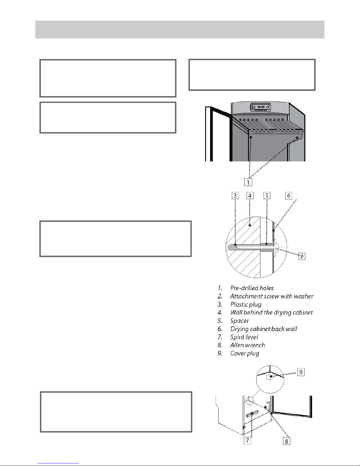
1. Check that the cabinet is firmly attached to the wall. See page 7 of this manual.
2. Check that no packaging material has been left behind.
3. Use a mild detergent with warm water and wash the inside and outside of the drying
cabinet. See the CARE section on page 14 of this manual.
HOW TO LOAD THE WASHING
The cabinet contains three sets of hanging rails.
Each set has 10 bars on which to hang the washing.
Hang items in the drying cabinet according to
how much space they require – not according to
their weight.
Fold back the middle and bottom sets of rails if
long garments are to be hung from the top set.
Hang gloves, hats, scarves and similar items on
the hangers attached to the inside of the door.
Slide the hanging rails forward to facilitate the
loading process. Push them back when not in
use and before closing the door.
Do not overload the drying cabinet. If you do, the
washing will become creased and dry unevenly.
Instead, leave space between the garments if
possible.
Avoid drying heavy items of clothing together
with lighter items as they have very different
drying times.
Make sure not to hang knitted items. These will
stretch as they are heavy when wet. Instead, lay
these items flat on top of the middle or lower set
of hanging rails.
For optimum efficiency, do not lay items flat on
the top set of hanging rails.
Avoid hanging textiles that are dripping or
soaking wet, as the drying cabinet is not
intended to collect large volumes of water. This
also leads to unnecessarily long drying times.
To avoid any potential transfer of colours, keep
light and dark/ coloured materials separate.
CAUTION! Do not dry articles that have
been previously cleaned in, washed,
soaked or splashed with petrol, or other
flammable/ explosive substances, as they
give off vapours that could ignite or
explode.
Drying tips:
Always follow the washing machine
instructions on garment care, if they are
provided.
If fabric softener or an antistatic product is
used, follow the manufacturer’s instructions
on their use.
Remove washing that is already dry. This
will reduce the drying time for the remaining
items.
Hang longer items nearest to the cabinet
walls and shorter ones towards the centre.
This allows for efficient airflow within the
cabinet and delivers the most effective
drying results.
Read this user manual before using
the drying cabinet for the first time.
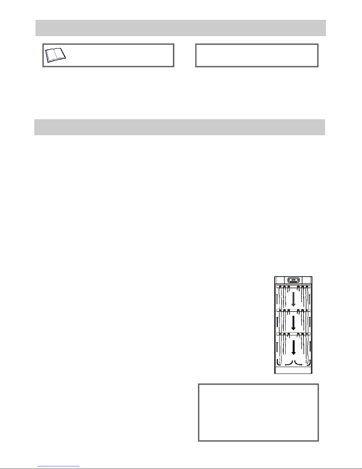
This figure shows
how the air flows
within the cabinet.

InstallaonandOperangManual Page11
CONTROL PANEL
1. Main power switch
2. Green light indicating cabinet is on
3. Display screen
4. Programme START/STOP
5. Automatic programme 40°
6. Automatic programme 60°
7. Manual time control (step function)
8. Reduce drying time (15 minute increments)
9. Increase drying time (15 minute increments)
DISPLAY
10. Current programme selection
11. Revolving symbol indicating drying process is in progress
12. With manual programmes, display shows total
programme time and programme countdown. With
automatic programmes, display shows cool down cycle
time only.
DRYING PROGRAMMES
The drying cabinet is equipped with two automatic, sensor-controlled programmes:
AUT 40° AUT 60°
In addition, the drying cabinet has four time-controlled programmes:
MAN 30° MAN 40° MAN 60° MAN --°(Fan only, no heat)
The automatic programmes end the drying cycle when the laundry is dry, or up to a maximum default
run time of 180 minutes.
The manually time-controlled programmes switch off after the set time has elapsed.
All heated programmes will finish with a 10 minute cool down period.
NOTE. Set the temperature and time to suit the most delicate articles to be dried.

InstallaonandOperangManual Page12
DRYING PROGRAMMES
START THE PROGRAMME
LAST USED DRYING PROGRAMME
Press the main power ON/OFF switch. A green light should appear, indicating that the cabinet is on.
The display shows the most recently run programme. If this is the desired programme, press
START/STOP.
Or to select an alternative drying programme, follow the instructions below:
TO SELECT AN AUTOMATIC PROGRAMME
Press the 40°or 60°button as required, then press START/STOP.
TO SELECT A MANUAL TIMED PROGRAMME
Using the MAN button, select between a 30°, 40°, 60°, or --° (fan only) programme. The display
shows the standard drying time for each programme.
The standard time can be increased or decreased with the +and -buttons.
Once the required drying programme has been selected, press the START/STOP button.
DURING THE PROGRAMME
The revolving symbol on the display panel indicates that the drying process is in progress.
COOLING DOWN
During the 10 minute cooling down period, the display indicates “COOL”. The time is counted down
with the remaining minutes shown within the time field on the display screen.
END PROGRAMME
When the cooling down period is complete, the drying process is finished. The display screen will
flash “END”. When the START/STOP button is pressed, or the door is opened, the current
programme ends and the last completed programme is displayed.
STOP THE PROGRAMME
To discontinue a drying process that is in progress, press the START/STOP button.
INTERRUPTING THE PROGRAMME
If the door is opened when the drying programme is in progress, the display shows “CLOSE DOOR”
and a 5 minute countdown period begins. The heat is turned off but the fan will continue to operate.
If the door is shut within this 5 minute period, the current drying programme will continue as follows:
Automatic programme: starts the drying cycle from the beginning, resulting in extended drying time.
Manual programme: re-starts and counts down from the time of interruption.
If the door is left open, the drying process is discontinued and has to be re-started manually.
NOTE. If power to the cabinet is not switched off within 10 minutes of the programme ending,
the display will go into sleep mode. To restore the display screen, press any button on the
control panel or open the door.
ADJUSTING THE DRYING PROGRAMMES
The drying cabinet’s two automatic programmes can be optimised in relation to the existing installation
conditions. This is done by adjusting the parameter values for the automatic programme concerned on
the control panel. This is only to be done if you find that:
The washing is not dried sufficiently or, The washing is over-dried.

InstallaonandOperangManual Page13
ADJUSTING THE DRYING PROGRAMMES
INTRODUCTION
The drying cabinet is equipped with two automatic programmes, 40°and 60°. The automatic
programmes end when the washing is dry. To determine when the washing is dry, a measured value is
taken from the exhaust duct and compared with a factory-set parameter;
parameter P4 for the 40° programme parameter P8 for the 60° programme.
It is primarily these two parameters that are adjusted to optimise the drying process of the automatic
programmes.
If you find the washing is under-dried, increase the parameter value for the relevant programme
If you find the washing is over-dried, decrease the parameter value for the relevant programme
Optimisation of the drying process must always take place in small steps. Start by adjusting the
parameter concerned by 1 - 2 units up or down, then check the result after the next drying process. If
required, make further adjustments in the same way.
PROCEDURE
The drying cabinet’s parameter list is accessed through the control panel. The parameter list appears one
line at a time on the control panel display.
1. Make sure that the main ON/OFF switch on the cabinet is OFF (the green indicator is also off).
2. Hold down the + and - buttons and press the main ON/OFF switch on the cabinet (the green light
will appear). The display lights up and shows the parameter P1 and its factory-set value.
3. Step through to the required parameter by pressing the MAN button repeatedly.
If you go too far, simply continue selecting forward until the display shows the correct parameter.
4. When the display shows the correct parameter, e.g. P8, press the +or - buttons to increase or
decrease the value.
5. To save the set value and return to the operating mode, press the START/STOP button. The display
now shows the last used programme.
NOTE. If you wish to restore the parameter list to the factory setting:
1. Go to the parameter display mode as describe in steps 1 - 2 above.
2. Hold down the 40°button and press the START/STOP button. The parameter list
reappears and the display shows P1 and its factory-set value.
3. To save the factory setting and return to operating mode, press the START/STOP button.
CARE
The inside and outside of the cabinet should be
cleaned with a mild soap solution and a damp
cloth.
Dust will collect on the top of the cabinet,
especially around the air intake. This can cause
operational faults within the cabinet, as well as
pose a fire hazard.
To avoid any potential problems, the top of the
cabinet should be vacuum cleaned at least once
a year, or more frequently depending on the
location of the cabinet and its application.
CLEANING
NOTE. High-pressure cleaning should not
be used.

InstallaonandOperangManual Page14
CARE
SERVICE AND REPLACEMENTS PARTS
If the connecting cable is damaged for any
reason, it must be replaced immediately.
All genuine parts can be obtained from the drying
cabinet dealer.
NOTE. A replacement lead may only be
installed by the manufacturer, the
manufacturer’s service agent, or another
authorised electrician.
TROUBLESHOOTING
Problem What you can do
The fan does not operate and
the cabinet is not heating up:
Check that the cabinet is connected to the power supply and that
the fuses are intact.
The drying cabinet is not
heating although the power
supply to the unit is confirmed:
If the green power indicator is not illuminated then the overheat
thermostat may have tripped out. Switch off the mains power
supply to the cabinet, leave for 20 minutes, and then restore the
power supply. Press the ON/OFF button several times to assess
whether the power has been restored (indicated by the green light).
Resonance or vibration occurs
when the fan is running:
Check that the cabinet is level in both planes and is securely fixed
to the wall. If the problem persists, try adjusting the feet ensuring
they are all in contact with the floor. See page 7 of this manual for
instructions.
The door switch is not working:
Figure shows an even gap between the
control panel and the top of the door.
To test the switch, select a drying programme, close the door, and
press START/STOP. If the display shows “CLOSE DOOR”, open
the door and manually press the switch with your finger - the switch
is found directly beneath the control panel, to the right-hand side. If
the drying programme resumes, the door switch is functioning
properly.
Check that an even gap exists between the control panel and the
top of the door. If they are not aligned properly, this may not
activate the switch. To rectify, ensure the cabinet is level and adjust
the feet and/ or door if necessary (see page 6 of this manual).
WARNING! Isolate the electrical supply and
remove the power plug before withdrawing
the service control unit.
In the event of further or persistent problems, please contact your dealer.
The service module can be removed from the
cabinet to enable any repairs or maintenance
work to be carried out.
You MUST first disconnect the cabinet from
the power source, then open the door before
removing the four screws underneath the control
panel. Carefully pull the service module out.
1. Service module
2. 4 x Torx screws

TECHNICAL DATA
Capacity: approx. 4 kg washing (cotton)
Evaporation rate: 17 g/min
Electrical connections: single-phase 220-240 V, 50 / 60 Hz, 10A
Fan motor: 35W
Heating element: 1.5 k/W
Maximum temperature: 70°C
Overheat cut-out: Yes
Hanging length: 16 metres
Dimensions: Height: 1700 mm (plus 15 mm adjustment)
Width: 595 mm
Depth: 620 mm (overall with pull handle 630 mm)
Weight: 57 kg
Sound level: 60 dB(A)
* Given values may vary depending on:
Spin speed of washing machine
Temperature and air humidity of room
Air circulation in the room (supply air, exhaust air)
Program Energy consumption
kWh/kg washing
Drying time Temp. maximum
AUT 40°C 0.4 approx. 2 h approx. 45°C
AUT 60°C 0.6 approx. 2 h approx. 65°C
MAN 30°C 0.3 (2 h 30 min) manual setting 15 min– 6 h approx. 35°C
MAN --°C 0.08 (8 h) manual setting 15 min - 12 h fan only
MAN 40°C 0.4 (2 h 30 min) manual setting 15 min - 4 h approx. 45°C
MAN 60°C 0.6 (2 h 30 min) manual setting 15 min - 4 h approx. 65°C
MANUFACTURING STANDARDS
See details on the drying cabinet data
plate (see page 2).
WHEN DRYING SPUN WASHING*
ENERGY CONSUMPTION AND DRYING TIMES
ELECTRICAL DIAGRAM AND DIMENSIONAL
DRAWING
The electrical wiring diagram and dimensional drawing
can be obtained from the distributor (see contact details
on page 2 of this manual).
They can also be found under the ‘Downloads’ section of
the Peko Drying Cabinet website;
www.pekodryingcabinets.co.uk.

EQUIPMENT LIMITED
Peko House
Northbridge Road
Berkhamsted
Herts.
HP4 1GE
Tel: 01442 872323 Fax: 01442 866900
www.pekodryingcabinets.co.uk
Table of contents
Other PEKO Dryer manuals