Now the most important advice in this entire manual:
DuringtherstightwerecommendthatyouhavethesupportofanexperiencedRCpilot.
There is no shame in asking for help – new full size aircraft are test own by skilled factory test pilots – and only then are regular pilots allowed to take
control. RC model control requires some skills and reexes people are not born with. It is not complicated to gain these skills – it just takes some time;
this will vary with your natural talent. Full size pilots start under the supervision of a skilled instructor; they learn to y at a safe altitude at rst, learn
landing and take-off techniques, and only then are they allowed to y solo. The same principles apply with RC models too. Please do not expect that
you will be able to put your model in the air and y it without any previous RC experience.
Many will have gained skills in controlling their favourite computer game character by hammering the control buttons or sticks. For model ying this
skill will have to be unlearnt!
The sticks movements required to control your model are small & gen-
tle. Many models including ALPHA 1500 are happier if you let them “y
by themselves” for most of the time, with small and gentle stick move-
ments to simply guide the model in the required direction. RC ying is
not about stick hammering, it is all about small stick movements, and
observing the effect of that stick movement. Only later is it possible to
anticipate the effect of larger stick movements that can be dangerous to
your model in the earlier stages of model ying.
Step1:Handlaunchandinitialtrimming
The model must be launched into wind every time. Throw grass into the
air to observe the wind direction.
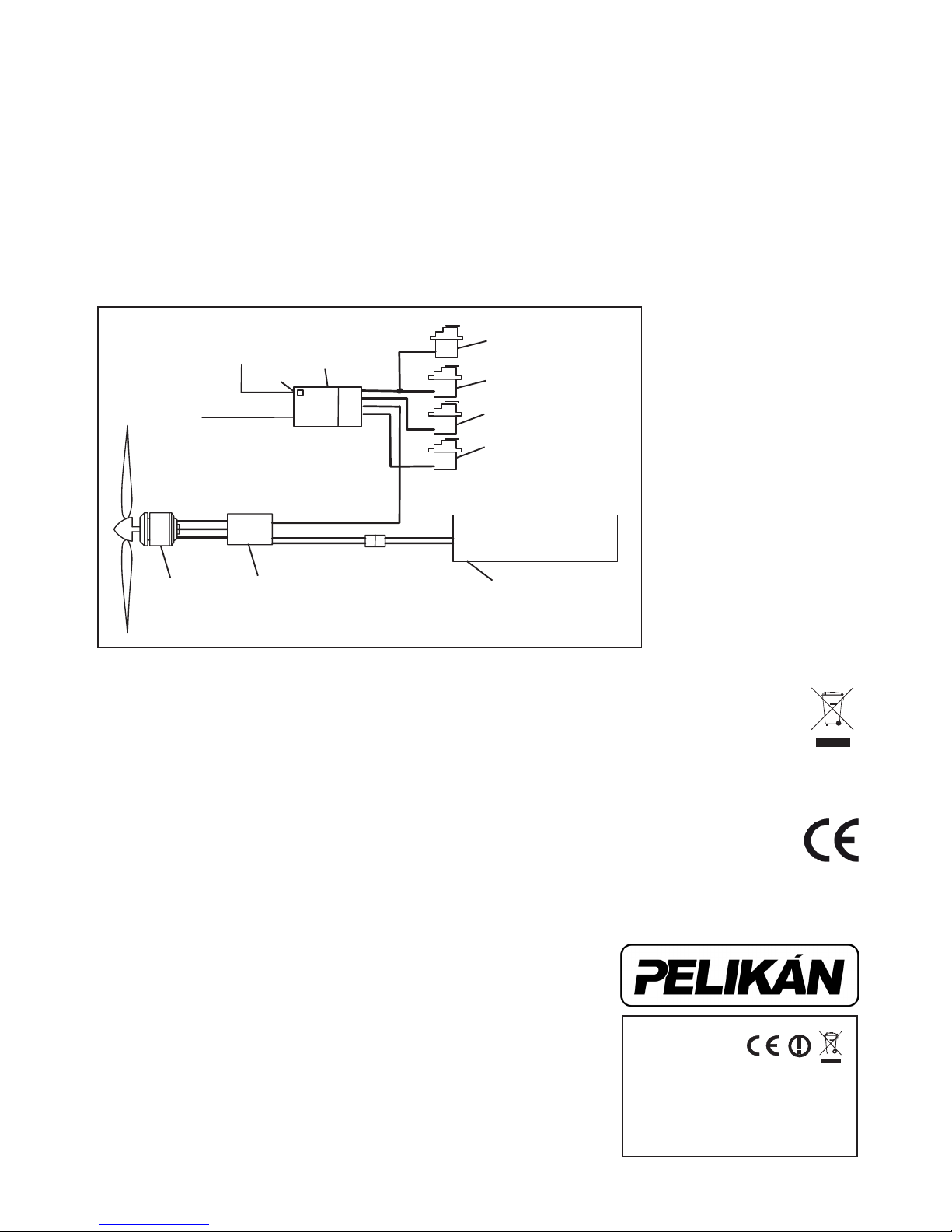
Turn on your transmitter.
Connectandputtheightpack intothebatterycompartmentandse-
cure the canopy.
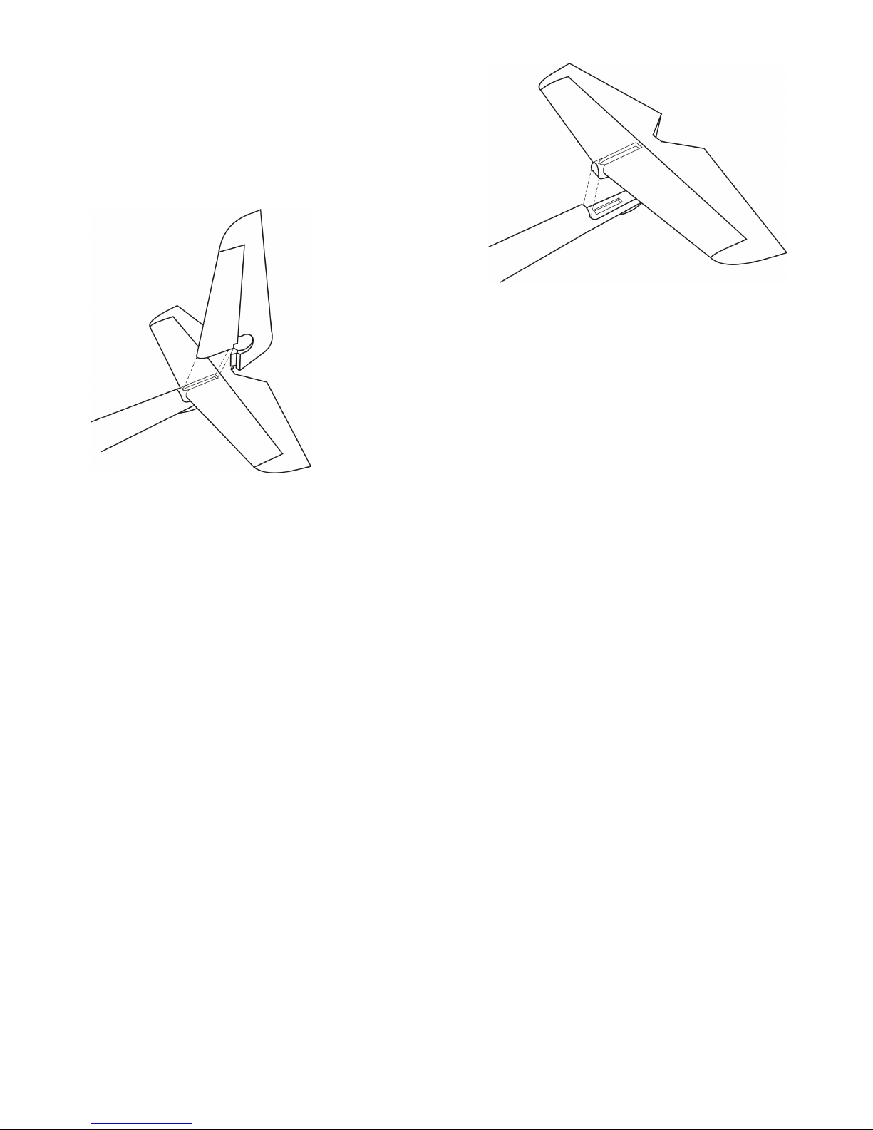
Hold your model with the wings and fuselage level (refer to the drawing)
–itisbettertoaskafriendtolaunchyourmodelthantodoeverything
byyourself–youcanthenconcentrateonthecontrols.
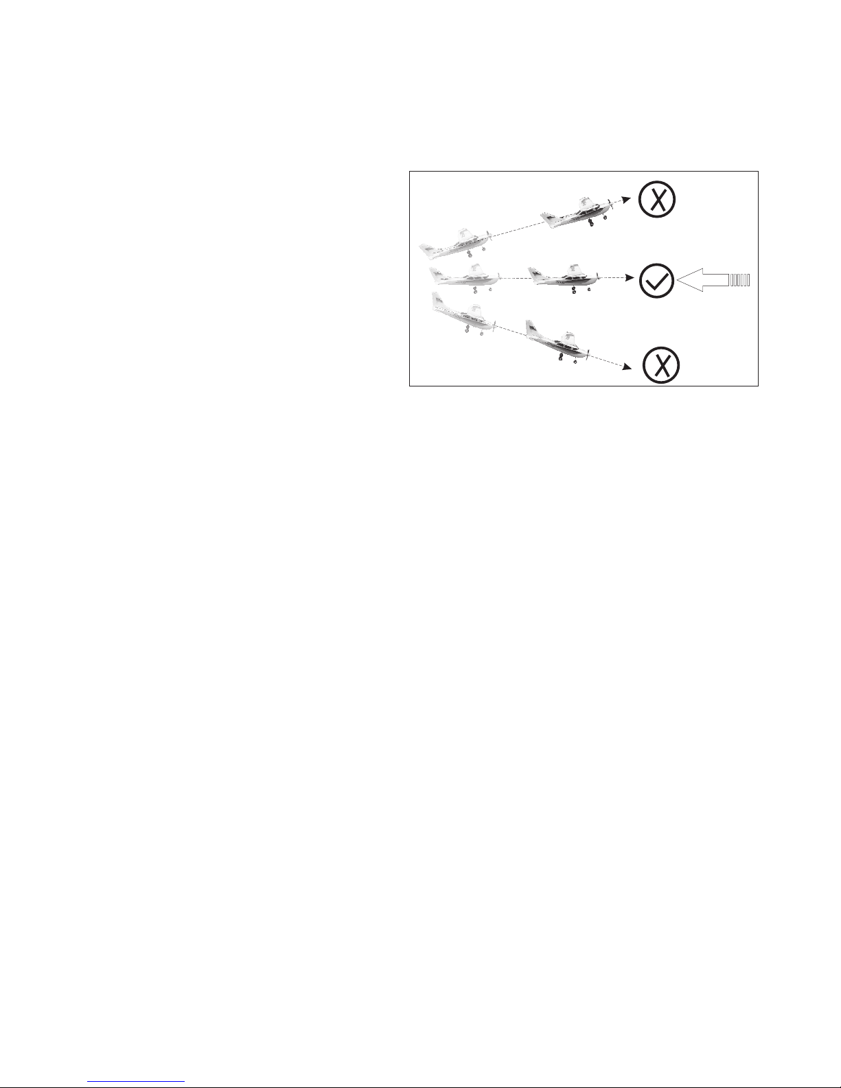
Givethemodelfullthrottleandlaunchyourmodelwithagentlepush straight and level.Youwillfeelthepointatwhichthemodelistryingtoy
naturally. Do not give it too strong a push. Do not throw your model with nose up, or greater than 10 degrees down. The model must have a certain
minimum speed from the very start to stay airborne. It is not enough to just “put” your model in the air.
If everything is OK ALPHA 1500 will climb gently. If your ALPHA loses altitude, pull the elevator stick very slightly towards you (just a little!) to achieve
a steady climb.
Step2:Flying
KeepyourALPHA1500climbinguntilshereachesatleast50minheight,thenthrottlebackthemotorjusttomaintainthelevelight.Therealying
fun begins now.
Please note:
ALPHA1500isnotalargemodel,sodonotletherytoofaraway.Pleaserememberyoucancontrolyourmodelonlysolongasyouareabletosee
the model’s orientation in the air. The safe range of your radio is much further than the range of your eyes!
How to control your model?
Incontrasttocarsorboats,aircraftyinthreedimensionalspacewhichmakesfullcontrolmorecomplex.Turningthesteeringwheelleftorright
makesaboatorcartoturnleftorright,applyingmorethrottlethevehiclespeedsup–andthisisit.Movingthecontrolsticksleftorrighthasmore
effect than simply turning the model. The aileron and rudder control will be explained later.
Pleasenote:thecontrolisfullyproportional–themoreyoumovethestick,themoremovementofthecontrolsurface.Theactualstickmovement
requiredismostlyquitesmall,andalmostneverfromoneendstoptotheother!
Elevatorcontrolsthemodelintheverticalaxis;applyupelevatorandyourmodel’snosewillraise(andthemodelwillclimbifithassufcientpower),
applydownelevatorandyourmodelwilldescend.Pleasenotethatyourmodelcanonlyclimbifithassufcientpowerapplied.Yourmodelwillnot
necessarily climb simply because you have applied up elevator, and will normally need full power applied for a safe gentle climb. If the climb angle is
toogreat,orthepowerappliedinsufcient,yourmodelwillloseyingspeeduntiltheminimum(stall)speed.Atthestallingspeed(whentheairow
starts to break away from the upper surface of the wing), your model will start to feel as though it is not responding as normal to control inputs, and
thendropwithlittlewarning–applydownelevatortoregainyingspeedandfullnormalcontrol.
Ailerons control the angle of bank. If you gently move the aileron stick to the left, your model will start bank to the left as long as you are holding the
stick.Nowifyoureturntheaileronsticktothecentreposition(neutral),yourmodelwillmaintainthebank.Ifyouwanttoresumestraightightyou
have to move the aileron stick to the opposite direction.
Rudder of a model without ailerons (you might be already familiar with) controls the angle of bank, which then controls the rate of turn. Natural stability
ofyourmodelkeepsthewingslevelinnormalstraightight.SinceyourALPHA1500featuresa“fullhouse”controlsincludingaileronsthatarethe
main means how to control the angle of bank, the use of the rudder is slightly different. You can even start to control your model without use of the
rudder-butyouwilllearnlatelythecorrectcoordinatedturnactuallyrequiresbothaileronandrudderinputs.
Anyturnrequiresanappropriatebankangle–ALPHA1500willynicebigandsafeatturnswithonlyasmallangleofbank.Duringinitialights
never use a bank angle of greater than 45 degrees. By planning the direction that the model will take, normal turns will be made with less than 30
degrees of bank.
Move the rudder to the left a little way, and your model will bank into a gentle turn. Increase the rudder input a little more, and your model will continue
turning to the left, but it will also start to descend (this is a good time to move the control stick to the centre to allow your model to recover from the
dive!).
Why does your model descend when only rudder is applied? Once the rudder leaves its exactly vertical position it also starts to work as an elevator
turneddowntellingyourmodeltodive.Wheninabankedturntomaintainlevelightitisnecessarytoapplyalittleupelevatortocountertheeffect
of the down turned rudder. (Actually, the reason why your model descends in the bank is much more complex - the wing gives less lift in the bank as
the vertical projection of the wing is the area that counts and you also have to beat the inertia that tries to keep your model in the straight ight...) The
elevator applied when your model is in a banked turn also works like a rudder - fortunately it helps to maintain the turn!
Inpractise,theaileronsareusedtoputyourmodeltothedesiredangleofbank,therudderisusedtomaintainit,andtheelevatorinput
helpstocontrolheightwhilstalsoincreasingtherateofturn.
Alternatively,youcanuseonlytheaileronstobankyourmodel,thenturnyourmodelusingjusttheelevatorandnallyresumethestraightandlevel
ightwiththeoppositedeectionofailerons.
6
Wind
Launch the model against the wind,
fuselage and wing level
THEFIRSTFLIGHT