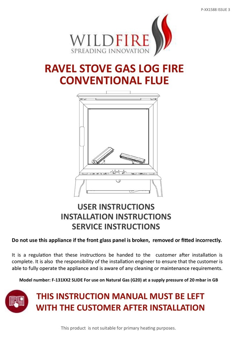
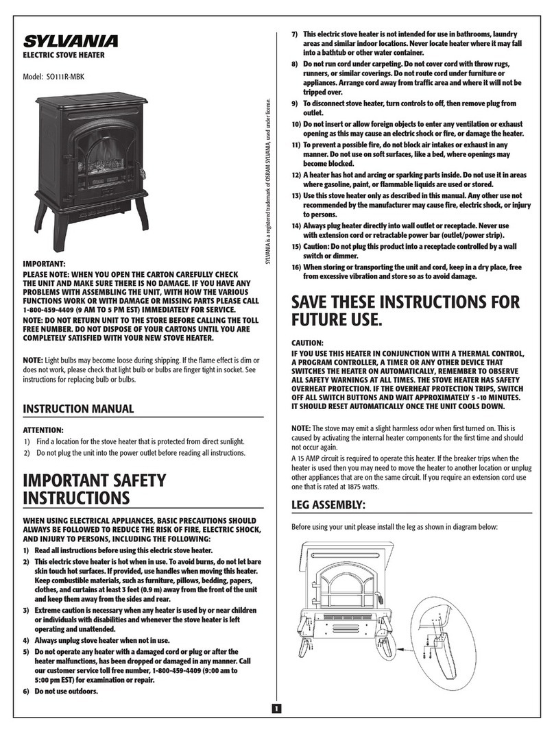
Pellet Fire Solutions RAVELLI Sofia Quick start guide

clean air approved
economical leading design
Sofia Wood Pellet Fire
Owners & Installation Manual
PLEASE READ THIS ENTIRE MANUAL BEFORE INSTALLATION, AND USE OF THIS WOOD PELLET FIRE.
FAILURE TO FOLLOW THESE INSTRUCTIONS COULD RESULT IN PROPERTY DAMAGE, BODILY INJURY,
OR EVEN DEATH.
Contact your local building or fire official about restrictions and installation requirement in your area.

ATTENTION
If you are a
not
a
registered
pellet
fire
installer,
and
do
not
have
legitimate access to the necessary passwords to install
and program the Sofia Wood Pellet Fire, you MUST NOT
install or attempt to install this fire.
The
Sofia Wood Pellet Fire requires technical programming
and
individualised
air
adjustments
to
ensure
it
will
operate
safely
and efficiently, and to avoid possible damage to
the fire or home.
Installation of the Sofia Wood Pellet Fire by a non-registered
installer
will
void
the
warranty,
and
may
result
in
your local
authority refusing to approve the necessary permits.
If
you
require
a
registered
Pellet Fire Solutions Installer,
2

1. Introduction........................................................................... 5
1.1 Specications.............................................................................. 5
2. Safety Warnings & Recommendations............................... 6
2.1 Installation................................................................................... 6
2.2 Decidingwheretolocateyourwoodpelletburningre......... 7
2.3 Ash............................................................................................... 7
2.4 Clinkering.................................................................................... 7
2.5 FillingFuelHopper..................................................................... 7
2.6 Flammable Liquids..................................................................... 8
2.7 OperatingInstructions............................................................... 8
2.8 Safety Devices............................................................................ 8
2.9 Responsibility.............................................................................. 8
2.10 Spare Parts................................................................................. 8
3. What are Wood Pellets?....................................................... 9
4. The Components of the Stove............................................. 9
4.1 Pellet Combustion....................................................................... 10
5. Maintenance and Cleaning.................................................... 11
5.1 Routine Cleaning......................................................................... 11
5.2 Glass Cleaning............................................................................ 11
5.3 Combustion Chamber Cleaning................................................ 11
5.4 Cleaning the Ash Drawer.............................................................
5.5 Cleaning the Pellet Hopper........................................................ 12
5.6 Servicing...................................................................................... 12
5.7 End of Season........................................................................... 14
5.8 Trouble Shooting......................................................................... 14
12
3
Owner's Section - Table of Contents

6. Operating your Pellet Fire..................................................... 15
6.1Description of Handheld Set....................................................... 15
6.2Handheld Touch Radio Initialization........................................... 15
6.3Description of the Display........................................................... 16
6.4 TimeandDateSettings............................................................... 17
6.5Loading the Auger....................................................................... 17
6.6 SettingOperatingTemperatureandPower............................... 18
6.7Turning the Device on................................................................. 18
6.8Operating Phases of the Stove................................................. 18
6.9.1 Alarms ........................................................................................ 25
7. MaintenanceRecord............................................................ 27
8. Warranty Information............................................................ 28
8.1 Warranty Coverage.................................................................. 28
8.2 Warranty Period........................................................ 28
8.3 Warranty Exclusions............................................................ 29
9. Proof of Purchase/Warranty............................................ 30
4

1. Introduction
This manual is designed for both the technician and the home owner.
Please read this entire manual before installing or operating your Ravelli
Wood Pellet Burning Stove. Failure to follow these instructions may result in property damage, bodily
injury or even death. Any unauthorized of the appliance, or use of replacement parts not
Note:
unit.theofback the on located is label rating heT
*Consumption will vary with the type of fuel used.
IMPORTANT: The above values were found during testing and may vary with the fuel type, climate and
installation style.
Testing Standard Description
Class I IP-20 AS/NZS 5078:2007
Appliance: AS/NZS 4866:2007
Residential Wood Pellet Stove
Voltage 220- 240 Volt Current: 2.92 – 3.18 Amps Frequency: 50Hz
Max Power Requirement
280 watts
Unit with full hopper: 155kg Hopper Capacity: 12kg
Mean Flue Gas Temp –
High: 1 65 degrees
Mean Flue Gas Temp-
Medium: 135 degrees
Mean Flue Gas Temp-
Low:
112 degrees
Fuel Consumption –
High: 1.45 kg per hour
Fuel Consumption –
Medium: 1.0 kg per hour
Fuel Consumption –
Low: 0.06 kg per hour
Heat/Power Output –
High: 9.0kw
Heat/Power Output –
Medium: 6.0kw
Heat/Power Output –
Low: 3.0kw
Average Particular Emissions (dry
weight) 0. 23 gms per kg
Average Emissions Rate
14mg/MJ
Average Efficiency
84%
Gross Value of pellets (dry weight)
120. MJ/kg
Fuel Type:
Wood pellets – 6mm dia, - complying
with draft standard AS/NZS 4014.6
2008
Ravelli Sofia Insert
Sofia Insert
5
recommended by the manufacturer is prohibited. All national and local regulations shall be complied
with when installing this appliance. Your local Pellet Fire Solutions dealer will be happy to assist
you in obtaining information with regards to your local building codes and installation restrictions.
1.1 Specifications
1.1.1 Rating label Location

• The place of installation of the stove
must comply with local &national regulations. The
stove must be fuelled only with quality pellets manufactured to standard AS/NZS4014.6.
The stove cannot operate with traditional wood.
• The stove must not be used as an incinerator.
• Before connecting the stove electrically, the connection of the exhaust spigot must be
joins must be sealed with maniseal exhaust cement).
• The protection grill inside the pellet tank must never be removed.
•
open the door of the stove whilst it is functioning.
•
•
• Scrupulously follow the maintenance program.
• Do not turn the stove off by disconnecting the electricity mains supply (use the
remote control.
2. Safety Warnings & Recommendations
Pellet quality is important, please read the following:
Your pellet heater has been designed to burn ¼” (6mm) diameter wood pellets, manufactured to the
AS/NZS 4014.6 only.
DO NOT use this appliance as an incinerator.
DO NOT use unsuitable and non recommended fuels, including liquid fuels, as this will void any
warranties stated in the manual.
The performance of your pellet stove is greatly affected by the type and quality of wool pellets being
burned. As the heat output of various quality wood pellets differs, so will the performance and heat
output of the pellet stove.
Caution: It is important to select and use only pellets that are dry and free of dirt, or any impurities such
as high salt content. Wood pellets manufactured to the AS/NZS 4014.6 standard are recommended.
Dirty fuel will adversely affect the operation and performance of the unit and will void the warranty. The
Pellet Fuel Industries (PFI) has established standards for wood pellet manufacturers. We recommend
the use of pellets that meet or exceed these standards. Ask your dealer for a recommended pellet type.
2.1 Installation
The stove must be installed and tested by specialised personnel approved by Pellet Fire Solutions.
Please read this manual before installing or operating the stove. If you require further information,
please contact your Pellet Fire Solutions dealer. Installation must be performed by authorized
personnel, who must give the purchaser a declaration of conformity of the appliance, and who will
installed. It is also necessary to take into consideration all the laws and national, regional, provincial
and local regulations present in the country in which the appliance has been installed. In the event
of failure to respect these precautions, Pellet Fire Solutions declines all responsibility.
IMPORTANT:
When the stove is operating, the surfaces, the glass, the handle and the pipes become
overheated: during functioning, these parts must only be touched with the adequate
protection.
Do not light the stove without having first performed the daily inspection as described in
the MAINTENANCE & CLEANING chapter of this manual (see page 11).
6

• Do not clean the stove until the structure and the ashes have cooled down completely.
Carry out all operations with maximum safety. .
be installed in a centrally located position within the home. This will assist
the appliance to perform to the level required.
the top of the unit, the heater should face the majority of the area to be heated.
a power source to function.
This is standard mains feed 240v plug - if this
.des ue bya mdae lnoisnetx edednuor g a,ytimixor pesol cn ielbaliavan usi
noitcejor pdrawro f aeva htsu mhcih w,ecafru selbitsubmoc-no n an odellatsn ie bo t
In accordance with the requirements of AS/NZS 2918:2018,
seismic restraint.
2.2 Deciding where to locate your wood pellet burning stove
1. Do not install the pellet stove in a bedroom or room where people sleep.
2. Locate the pellet stove in a large and open room that is centrally located in the house.
This will optimise heat circulation.
3. Check clearances to combustibles (refer page 35).
Sofia should
Sofia
Sofia
of
a minimum of 150mm from the glass door
.
Please check all clearances to combustibles as listed on page 35 of this Owner’s/Technical
manual.
is
Sofia must be secured by
As the Sofia heats space by convecting air through
requires
7
2.3 Ash
The ash content of the fuel and operation of your stove will directly determine the frequency of cleaning.
The use of high ash fuels may result in the stove needing to be cleaned daily. A low ash fuel may allow
longer intervals between cleaning.
2.4 Clinkering
Clinkers are silica (sand) or other impurities in the fuel that will form a hard mass during the burning
process. This hard mass will block the air flow through the burn pot liner, and affect the
performance of the stove. Any fuel, even approved types, may clinker. Check the burn pot liner
daily to ensure that the holes are not blocked with clinkers. Refer to the Routine Cleaning and
Maintenance section.
2.5 Filling Fuel Hopper
Check hopper for foreign objects, then empty the bag of pellets into the hopper. DO NOT OVER FILL ,
as miscellaneous pellets could smoke if left to rest on an operating stove.
Store pellets at least one metre (1m) away from the pellet stove.
Warning: parts of the appliance, especially the external surfaces, will be hot to touch when in operation
so use due care.

6
7
• Poor maintenance.
• Failure to observe the instructions in the manual.
• Use not compliant with the safety instructions.
• Installation that is not compliant with the regulations in force in the country.
•
• manufacturer.
• Use of spare parts that are not original.
• Exceptional events.
2.10 Spare Parts
Use original spare parts only. Do not wait for the components to be worn before replacing them.
Replace a worn component before it is completely broken, to prevent any accidents caused by
the sudden breakage of components. Perform the periodic maintenance checks as described
in the dedicated chapter on “Maintenance and Cleaning” on page 11 .
Installation by personnel who are not qualified or authorised.
a diameter of 6mm, manufactured to the AS/NZ4014.6 or higher must be used with the stove.
2.8 Safety Devices
The stove is fitted with a sophisticated safety systems so that, in the case of breakage of one of the
individual parts, or defects in the flue, no damage will be caused to the stove and the room in which it
is installed. In any case, when a problem arises, the pellets stop falling immediately and the switch off
phase is activated. The corresponding alarm will be shown on the display. The details can be seen in
the chapter on the alarms (see page 25 and 26).
2.9 Responsibility
Pellet Fire Solutions declines all responsibility, both civil and criminal, with the delivery of this
manual, for any accidents deriving from partial or total failure, to observe the instructions it contains.
Pellet Fire Solutions declines all responsibility deriving from the improper use of the stove, from its
incorrect use by the user, by unauthorised modifications and/or repairs, or from the use of spare parts
which are not original. The manufacturer declines all direct, civil or criminal responsibility due to:
2.6 Flammable Liquids
Never use gasoline, gasoline – type lantern fuel, kerosene, charcoal lighter fluid or similar liquids to
start or “freshen” up a fire in the stove. Keep all such liquids well away from the stove while it is use.
2.7 Operating Instructions
The stove is completely automated and will self-regulate the ignition phase, five levels of power and
the switching off phase, guaranteeing safe functioning. The burn pot used for combustion allows most
of the ashes produced by the combustion of the pellets to fall into the collection drawer. However,
it is recommended that you check the burn pot every day, as not all pellets have high standards of
quality, and could leave residue that is difficult to remove. The glass has special air circulation for self-
8

3. What are Wood Pellets?
Wood pellets are made from sawdust and wood shavings. The material used cannot contain any foreign
substance such as glue, varnish or synthetic substances. Subjecting it to high pressure, the wood is
pressed through a plate with holes, and due to the high pressure, the sawdust is heated activating the
natural binders of the wood. Thus, the pellets keep their shape even without the addition of bonding
substances. The density of the wood pellet varies according to the type of wood and can be 1.5 – twice
greater than that of natural wood. The diameter of the cylindrical rods is 6-10 mm and their length can
vary between 10 and 50 mm. Their weight is equal to about 650 kg/m. Due to the low content of water
(approx 8%) they have a high energy content. The standards AS/NZS4014.6 de ne the quality of the
pellets:
Do not put the bag of pellets on the cast parts during the loading operations.
The pellets must be transported and stored in a dry place. They swell on contact with any moisture
and cannot be used. They must always be protected from moisture, both during transport and in
storage. Ravelli recommends using a pellet with a diameter of 6 mm for the stove.
4. The Components of the Stove
9

8
4.1 Pellet Combustion
Combustion is simply a chemical reaction between combustible and carburant. The result of this
reaction is the heat.
The three elements that are required for combustion are:
-Combustible (pellet)
-Carburant (oxygen available in the air)
-Ignition (electrical resistance for ignition)
To achieve combustion, the combustible and the carburant must be available in the correct proportions.
The reaction between combustible and carburant is made by an external starter. Ignition can be created
by direct contact with a heat source, or by a spark. Incorrect combustion is evident when the flame is
too tight, and there are too many incandescent pellets in the firepot.
INCORRECT combustion - the ame is weak and there are a lot of unburned
pellets in the repot. Check rst that the ash pan is properly closed. Then
adjust set pellet/air increasing the air percentage (from 0 up to +5). If this
doesn’t work, try increasing the loading quantity of the pellet (from 0 up to -5)
to reach the ame condition shown in picture 3.
If with the adjustments done, the ame is not reaching the condition shown
in picture 3, contact After Sales Service.
The combustion is NOT CORRECT, the ame is weak and a lot of unburned
pellet wood in the repot. Check rst that the ash pan is properly closed.
Then adjust set pellet/air increasing the air percentage (from 0 up to +5); in
the event this is not enough, increase the loading quantity of the pellet (from
0 up to -5) to reach the ame condition shown in picture 3.
If with the adjustments done, the ame is not reaching the condition shown
in picture 3, contact After Sales Service.
The combustion IS CORRECT, full ame, yellow/white, and minimum
quantity of pellet in the repot.
The combustion is ne, and no ash.
The picture 3 shows a flame with a stove working at power P5.
OXYGEN
HEAT
PELLET
10

5. Maintenance and Cleaning
Maintenance of the stove must be performed at least once a year and should be planned in advance with the
Technical Assistance Service.
In some conditions, such as turning the stove on and off or inappropriate use, the combustion products can
contain small soot particles that build up in the smoke evacuation system. This can reduce the cross-section of
the smoke duct and pose a fire risk.
The smoke evacuation system must be inspected and cleaned at least once a year.
The maintenance operations must be carried out when the stove is cold and with the electrical power supply
disconnected.
Before completing any maintenance operation, adopt the following precautions:
•Make sure that all stove parts are cold.
•Make sure that the ashes are completely cold.
•Always operate with equipment that is appropriate for maintenance.
•When maintenance is nished, re-install all of the dis-assembled parts before restarting operation.
! IMPORTANT The quality of the pellet, the stove operating mode and combustion control can affect
maintenance activity frequency.
5.1 Routine Cleaning
! IMPORTANT Perform the cleaning operations so as to guarantee correct stove operation. The table
below lists the necessary cleaning operations required for correct stove operation.
5.2 Glass Cleaning
With a cold stove, clean the glass with a cloth and glass cleaner.
Note: there are stove glass cleaning products available on the market.
5.3 Combustion Chamber Cleaning
To clean the ash drawer, proceed as follows:
step action
1
The stove requires asimple yet frequent cleaning in order to guarantee suitable yield and regular operation. Vacuum the
combustion
chamber every day using a bin ash vacuum, making sure that the ashes are completely cold.
PARTS / FREQUENCY 1 DAY 2-3 DAYS 60-90 DAYS
Combustion chamber
•
Combustion grille
•
Ash drawer
•
Glass
•
Extraction duct
•
Combustion chamber
11

5.4 Cleaning the Ash Drawer
The ash drawer must be cleaned every 30 days, (depending on the amount of time the stove is used and what type of pellet is used).
To clean the ash drawer, proceed as follows:
5.5 Cleaning the Pellet Hopper
To clean the pellet tank, proceed as follows:
step action
1Periodically remove the wood sawdust accumulated on the bottom of the tank, using a vacuum cleaner.
5.6 Servicing
This operation must be carried out by a Ravelli Assistance Centre.
Schedule this type of cleaning with the Ravelli Assistance Centre.
The smoke conduit must be cleaned every 3 months.
step action
1Open the hatches.
2Clean the ashes, eventually use a brush or similar and reassemble everything.
Note: the hatches are equipped with gaskets, therefore, before reassembling them, make sure that the gaskets are not
worn.
Note: The operation must be carried out with a cold stove, using an ash-type aspirator.
Extraordinary maintenance
Extraordinary maintenance activities must be carried out by staff from the Authorised Assistance Centre.
Do not wait for components to be deteriorated by use before proceeding with their replacement. Replace a worn
component before it is completely broken to prevent any damage caused by sudden component breakage.
PARTS / FREQUENCY 60- 90 DAYS 1 SEASON
Inspection hatch
•
Deep combustion chamber cleaning
•
Door gasket
•
Chimney
•
Schedule the above extraordinary maintenance activities with the Authorised Assistance Centre.
Deep combustion chamber cleaning
! IMPORTANT This operation must be carried out by a Ravelli Assistance Centre.
Schedule this type of cleaning with the Ravelli Assistance Centre.
Slide for ashes
! IMPORTANT
12

To clean the combustion chamber, proceed as follows:
1- Remove the vermiculite stop
2-Deep cleaning
Clean up
INSPECTION HATCH
GASKET
Note: The operation must be carried out with a cold stove, using an ash-type aspirator.
13

5.7 End of Season
At the end of every season we recommend vacuuming out any ash and dust that may still be inside.
5.8 Trouble Shooting
The stove does not work
• closely follow the directions in the dedicated chapter of this manual.
• make sure that the air intake duct is not obstructed;
• make sure that the smoke evacuation system is clean and not obstructed;
• make sure the chimney is sized for the stove power;
• make sure that the air intake in the room is clear of any obstructions and that there are no other combustion appliances or
extraction hoods that create a vacuum in the room;
Difcult lighting
• closely follow the directions in the dedicated chapter of this manual;
• make sure that the air intake duct is not obstructed;
• make sure that the smoke evacuation system is clean and not obstructed;
• make sure the chimney is sized for the stove power.
•make sure that the air intake in the room is clear of any obstructions and that there are no other combustion appliances or
extraction hoods creating a vacuum in the room.
Smoke leakage
• Check the draught of the chimney.
• Check whether the seals on the door, drawer and smoke evacuation system are intact.
•Make sure there is no ash obstructing the primary air ow grille.
The glass gets dirty easily
• Only use recommended fuels.
• Check the draught of the chimney.
14

6. Operating your Pellet Fire
6.1 Description of the Handheld Set
The handheld set is shown in the picture below:
The information below will allow you to become familiar with the product and achieve the best performance.
The handheld set, after a short screen showing the Ravelli logo, will list the languages available in the menu.
User’s manual HANDHELD TOUCH RADIO User’s manual HANDHELD TOUCH RADIO
Pag.18 Pag.19
Vers. 01 of:07.04.14 Vers. 01 of:07.04.14
Examples of installation of a pellet insert
In this type of installation we can notice that the tting
was used to enable connecting the insert to the chim-
ney (so-called “bayonet” mount).
For safety reasons and to ensure proper operation, we
recommend you t pipes into the chimney. (Fig.7)
It is recommended to perfectly match the insert with
the tting, to prevent leaks of smoke during the work
phase.
Fig.7
Fig.8
Exploded view of T t
Protection from rain
Wiring
Connect the power cord to the back of the stove and then to a wall socket. The I/O switch in the gure
should be set to I to power the stove. If voltage is not supplied check the state of the fuse installed in
the box below the switch (4A fuse). During the periods of inactivity, we recommend you disconnect the
power cord of the stove.
Preliminary Operations
NEVER INSERT INTO THE TANK OTHER KIND OF FUEL OTHER FROM THE PELLETS
COMPLYING WITH THE SPECIFICATIONS BELOW
The handheld set is shown in the picture below:
Description of the handheld set:
The information below will allow you to become familiar with the product and achieve the best performance.
How to insert the batteries in the handheld set:
Remove the protective cover of the battery on the back of the remote control as shown in Figure A, and insert the 3 batteries
(mini pen style battery AAA 1.5V) in the housing of the handheld set and observe the poles. Install the battery protective cover
as shown in gure B
The handheld set, after a short screen showing the Ravelli logo, will list the languages available in the menu.
Select the desired language using the scroll keys and conrm your selection with the conrmation button.
ON/OFF or reset from“Sleep” mode key.
Display
Key for accessing the MENU and back
6Conrmation key
1
2
5
6
4
3
Figure A Figure B
Here you can see the possibility to slide
the insert; this operation can only be performed
with the stove turned off for loading pellets or during
regular checks. (Fig.8)
IT IS STRICTLY FORBIDDEN
TO REMOVE THE STOVE DURING
THE WORK PHASES; THE FUME
MAY DISPERSE INTO THE
In “Sleep” mode, the handheld set
screen is obscured, keeping however
active the radio communication with
the stove to reduce battery con-
T tting with
inspection ash
collector cap
Flue
Protection from rain
Pipe
Flue
Pipe
What to check befor turning on the stove
Make sure you have removed all parts that pose the risk of burns from the combustion chamber or glass (various instructions or
stickers).
Before turning on the stove, make sure you have tted the grate on the support base and check that the door and the ash drawer
are properly close.
How to load the pellets
Fuel supply consists in the insertion of pellets from the top of the stove, by opening the door. During pellet loading prevent the pel-
let bag from coming into contact with hot surfaces.
User’s manual HANDHELD TOUCH RADIO User’s manual HANDHELD TOUCH RADIO
Pag.18 Pag.19
Vers. 01 of:07.04.14 Vers. 01 of:07.04.14
Examples of installation of a pellet insert
In this type of installation we can notice that the tting
was used to enable connecting the insert to the chim-
ney (so-called “bayonet” mount).
For safety reasons and to ensure proper operation, we
recommend you t pipes into the chimney. (Fig.7)
It is recommended to perfectly match the insert with
the tting, to prevent leaks of smoke during the work
phase.
Fig.7
Fig.8
Exploded view of T t
Protection from rain
Wiring
Connect the power cord to the back of the stove and then to a wall socket. The I/O switch in the gure
should be set to I to power the stove. If voltage is not supplied check the state of the fuse installed in
the box below the switch (4A fuse). During the periods of inactivity, we recommend you disconnect the
power cord of the stove.
Preliminary Operations
NEVER INSERT INTO THE TANK OTHER KIND OF FUEL OTHER FROM THE PELLETS
COMPLYING WITH THE SPECIFICATIONS BELOW
Description of the handheld set:
1
2
5
6
4
3
Figure B
Here you can see the possibility to slide
the insert; this operation can only be performed
with the stove turned off for loading pellets or during
regular checks. (Fig.8)
IT IS STRICTLY FORBIDDEN
TO REMOVE THE STOVE DURING
THE WORK PHASES; THE FUME
MAY DISPERSE INTO THE
In “Sleep” mode, the handheld set
screen is obscured, keeping however
active the radio communication with
the stove to reduce battery con-
sumption.
T tting with
inspection ash
collector cap
Flue
Protection from rain
Pipe
Flue
Pipe
What to check befor turning on the stove
Make sure you have removed all parts that pose the risk of burns from the combustion chamber or glass (various instructions or
stickers).
Before turning on the stove, make sure you have tted the grate on the support base and check that the door and the ash drawer
are properly close.
How to load the pellets
Fuel supply consists in the insertion of pellets from the top of the stove, by opening the door. During pellet loading prevent the pel-
let bag from coming into contact with hot surfaces.
User’s manual HANDHELD TOUCH RADIO User’s manual HANDHELD TOUCH RADIO
Pag.18 Pag.19
Vers. 01 of:07.04.14 Vers. 01 of:07.04.14
Examples of installation of a pellet insert
In this type of installation we can notice that the tting
was used to enable connecting the insert to the chim-
ney (so-called “bayonet” mount).
For safety reasons and to ensure proper operation, we
recommend you t pipes into the chimney. (Fig.7)
It is recommended to perfectly match the insert with
the tting, to prevent leaks of smoke during the work
phase.
Fig.7
Fig.8
Exploded view of T t
Protection from rain
Wiring
Connect the power cord to the back of the stove and then to a wall socket. The I/O switch in the gure
should be set to I to power the stove. If voltage is not supplied check the state of the fuse installed in
the box below the switch (4A fuse). During the periods of inactivity, we recommend you disconnect the
power cord of the stove.
Preliminary Operations
How to insert the batteries in the handheld set:
Remove the protective cover of the battery on the back of the remote control as shown in Figure A, and insert the 3 batteries (mini
pen style battery AAA 1.5v) in the housing of the handheld set and observe the poles. Install the battery protective cover as
shown in Figure B
Figure A
Select the desired language using the scroll keys and confirm your selection with the confirmation button.
Increase button “UP” (selection key)
Decrease key “DOWN” (selection key)
1
2
5
6
4
3
Figure A Figure B
Here you can see the possibility to slide
the insert; this operation can only be performed
with the stove turned off for loading pellets or during
regular checks. (Fig.8)
IT IS STRICTLY FORBIDDEN
TO REMOVE THE STOVE DURING
THE WORK PHASES; THE FUME
MAY DISPERSE INTO THE
In “Sleep” mode, the handheld set
screen is obscured, keeping however
active the radio communication with
the stove to reduce battery con-
sumption.
T tting with
inspection ash
collector cap
Flue
Protection from rain
Pipe
Flue
Pipe
What to check befor turning on the stove
Make sure you have removed all parts that pose the risk of burns from the combustion chamber or glass (various instructions or
stickers).
Before turning on the stove, make sure you have tted the grate on the support base and check that the door and the ash drawer
are properly close.
How to load the pellets
Fuel supply consists in the insertion of pellets from the top of the stove, by opening the door. During pellet loading prevent the pel-
let bag from coming into contact with hot surfaces.
ITALIANO
DEUTSCH
ENGLISH
FRANCAIS
DANSK
NEDERLANDS
ESPANIOL
6.2 Handheld touch radio initialization
In order to operate correctly, the handheld set should be interfaced with the electronic board installed inside the stove. For this
eason, on display appears the following message:r
If the handheld set is used for the first time, select YES using the selection keys and confirm with the dedicated key. On the
display of the handheld set appears the following:
FIRST INSTALLATION?
YES
old down for a few seconds the button of radio communH ication (RADIO ADJ) of the PCB, located on the back of the stove, to
ialize the device.init
PRESS THE KEY RADIO
ADJ ON THE STOVE
1
2
3
4
5
15

The ashing yellow LED indicates that the circuit board is waiting to receive the signal from the handheld set.
pressing the enter key on the handheld set, the components start communicating with each other. A check signBy on the display,
accompanied by a sound signal, shows that the initialization of the handheld set has been completed sucessfully
4
32
1 5
1
2
4
5
Serial port
Handheld cable connection socket
3ADJ radio: button to connect your handheld to the board
Signalling LED
Red: active alarm
Yellow: Waiting communication with the handheld set
Green: Cooker switched on
Cooker ON/OFF key
6.3 Description of the display
The display of the handheld set is described below (in stand-by mode):
hen you replace the batteries, you do not have to run the initialization procedure of the handheld set. In this case, when W
on display appears the message “FIRST INSTALLATION ?”, select NO and press the confirmation ke .
2
3
1
After 5 minutes of inactivity, the display of the handheld set turns dark, switching to “SLEEP” mode, while maintaining the
radio connection with the stove. By pressing the key ON/OFF, the display becomes active again.
The first pressure of any key with the display active, lights u its backlight, but it is not, however ,
considered a command.
isplay is subdivided into three parts:eTh d
It shows the current room temperature measured by the handheld set. Moreover, if you press the DOWN scroll key you will
display the temperature settings that can be changed using the two UP/DOWN keys. Any change made is conrmed automatically
within 3 seconds from the change or by pressing the conrmation key. A sound signal indicates that the change has been conrmed.
Icon indicating the status of the stove (see synthetic phase diagrams).
In the inactive phases (combined with the second part of the display) indicates the state of the stov
In the active phases, it indicates the operating power of the stove.
In addition, by pressing the DOWN scroll button, you can display the power settings, that can be edited using the two scroll keys UP/
DOWN: The confirmation of any change takes place automatically within 3 seconds from the change or by pressing the
confirmation key. A sound signal indicates that the change has been confirmed.
3
1
3
2
16

MENU USER USER
SETTINGS
SETTINGS
DATE-TIME
USER COMFORT CLIMA
MANUFACTURER
ENGINEER
ENABLE EXT. TH.
CONTRAST
FW VERSION
ADJUST
LANGUAGE
MOS
SCREW FEEDING
CHRONOTHER TAT
AIR-PELLET SET
STOVE STATE
Press the key “access menu” to
access
the
MENU page
Press the key
“conrm” to
access the
SETTINGS
page
Press the key
“conrm”
to access the
USER page
Press the key “con-
rm”
to access the page
DATE-TIME
Press the key “selection” for
“selection”
to switch to the second page
of USER MENU and select
SETTINGS.
Press the increase key to change every single value
Press “conrm” to conrm the settings and switch to the next
value.
By pressing the key “back” for several times you will display
the stand-by page.
6.4 Time and date setting
Below are given the steps for accessing the relative menu.
6.5 Loading the Auger
MENU USER
SCREW FEEDING
SCREW FEEDING
CHRONOTHERMOSTAT
AIR-PELLET SET
STOVE STATE
USER
MANUFACTURER
ENGINEER
Carry out this operation to facilitate stove’s first start operations; You should also check that you have introduced pellets
into the hopper and wait until the stove is in “SHUTDOWN” or “FINAL CLEANING” mode. The number expressed in sec-
onds indicates the rotation time of the infeed screw during the first loading cycle. Once this time has elapsed, the infeed
screw stops immediately and then pellets are emptied from the grate before turning on the equipment.
Below are given the steps for accessing the relative menu.
Press the key “access
menu” to access
the
MENU page
Press the key
“conrm”
to access the
USER page
At the end of the auger loading, the display shows 0 “and automatically switches to the USER menu page.
Press the key for several times until the Stand-by page is displayed.
Press CONFIRM to enable
the rotation of the auger
17

ALWAYS EMPTY THE BRAZIER BEFORE TURNING THE STOVE ON AND ALWAYS CHECK
THAT ALL NONE OF ITS HOLES IS CLOGGED NEVER EMPTY THE RBAZIER INSIDE THE HOPPER.
FIRE HAZARD.
6.6 Setting Operating Temperature and Power:
Set the two values following the indications given in the chapter “Description of thedisplay”
6.7 Turning the Device on:
Keep the key ON/OFF pressed for a few seconds to turn on the stove.
The appearance of the message “ADJUST THE RDS SYSTEM” indicates that the initial parameter testing procedure
and calibration has been unsuccessfully. This indication does not cause stove blockage (see the WARNING POP UP
section).
On the display of the handheld set appears the following:
Press and hold the ON/OFF button to turn off the stove door, and reset any alarms triggered.
In case the infeed screw operations described above have not been executed, the stove may fail to turn on. In
this case, carry out the operations described above and empty the brazier and reset the alarm.
If the stove still fails to turn on, check that the grate is properly installed and perfectly adherent to the base, and also check that
there are no deposits that prevent the smooth passage of air to enable ignition. If the problem persists, contact the support
service.
Sequence of ignition phases
SWITCH-ON- initial pellet loading phase;
WAIT FLAME - ame
development wait
phase;
FLAME PRESENT - ame stabilization
phase and reduction of combustible
inside the brazier;
What happens if the batteries are empty?
If the battery is discharged, within the
“drop” is shown a symbol that indicates
that the battery is empty, while
maintaining active the features of your
device.
WORK - operation phase
described in
the dedicated chapter;
As soon as the level of the battery
prevents the radio communication the
handheld set displays on full screen
the picture of empty battery and all
device functions are locked until the
batteries are replaced
CONNECT AN EXTERNAL THERMOSTAT WITH A SIMPLE DRY CONTACT, THEREFORE, NOT POWERED. MORE-
OVER, WE RECOMMEND YOU USE A THERMOSTAT WITH A MINIMUM OFFSET OF 3°C IF YOU INTEND TO USE
THE COMFORT CLIMA FUNCTION.
6.8 Operating Phases of the Appliance
Modulation
During the work phase, the appliance should reach the room temperature set; when this condition is met, the stove switches to
MODULATION mode in which fuel consumption and ventilation are minimum.
If you wish to detect the ambient temperature by means of an external thermostat (optional), this must be connected to
the appropriate connector on the rear side of the stove; and you will have to activate the reading in “SETTINGS - EN -
ABLE THERMOSTAT.” On display appears the writing TON / TOFF based on thermostat request.
18

MENU
USER
MANUFACTURER
ENGINEER
USER USER
COMFORT CLIMA
COMFORT CLIMA
COMFORT CLIMA
COMFORT CLIMA
ENABLE COMFORT
ENABLE COMFORT
ENABLE COMFORT
RESTART DELTA
RESTART DELTA
SHUTDOWN DELAY
SHUTDOWN DELAY
SHUTDOWN DELAY SHUTDOWN DELAY
ENABLE COMFORT ENABLE COMFORT
COMFORT CLIMA DELTA COMFORT CLIMA DELTA
RESTART DELTA
SHUTDOWN DELAY
SETTINGS
SCREW FEEDING
CHRONOTHERMOSTAT
AIR-PELLET SET
STOVE STATE
Comfort climate
The activation of this function enables the stove to reduce pellet consumption by activating the modulation phases, after the desired
temperature has been reached. Subsequently, the stove checks that the temperature is maintained steady for a preset time. If this
condition is met, it automatically switches off, and on display appears the writing ECO.
The stove turns on again when the temperature drops below the set threshold.
Below are given the steps for accessing the relative menu.
Press the key
“access menu” to
access
the
MENU page
Press the key
“conrm”
to access the
USER page
Once you have accessed the Climate Comfort menu, it is possible to operate on the 3 types of settings dedicated to the function:
Press the key for several times until the Stand-by page is displayed.
Press the key “selection” for
“selection”
to switch to the second page
of USER MENU and select
CLIMATE COMFORT.
USING THIS METHOD, IT IS NECESSARY TO VERIFY THAT AFTER EACH AUTOMATIC SHUTDOWN
THE GRATE IS ALWAYS VERY CLEAN TO GUARANTEE CORRECT AUTOMATIC SWITCH ON.
AUTOMATIC SWITCH ON.
The rst setting allows the activation of the CLIMATE COMFORT function. This function is intended to ensure that the room tem
-perature set is maintained steady upon setting the maximum period of “X” minutes (SWITCH-OFF DELA
Y: 5 MIN) before switch-ing to ECO STOP phase. The STOVE maintains this state until the temperature drops below the set
value (CLIMATE COMFORT DELTA : 5).
For example, with the room temperature at 21 ° C, the stove switches of f when this temperature is
reached and restarts when the temperature reaches 15°C (21°C - 5°C - 0,5°C tolerance).
You can also activate the function using an external thermostat, keeping in mind that this does not include the value of the hyster
-esis.
We recommend you use an external thermostat with a hysteresis value that can be set to maximum 3°
C. The operation of the stove could activate the switch ON/OFF phases for several times during the day;
this may affect the service life of the ignition coil.
19

MENU
MENU
CHRONO
ENABLE CHRONO
ENABLE CHRONO
SET CHRONO
SET CHRONO
SET CHRONO
SET CHRONO
SET CHRONO 1
SET CHRONO 2
SET CHRONO 3
SET CHRONO 4
ENABLE CHRONO ENABLE CHRONO
CHRONO
USER
MANUFACTURER
ENGINEER
MANUFACTURER
ENGINEER
USER USER
USER SCREW FEEDING SCREW FEEDING
CHRONOTHERMOSTAT
CHRONOTHERMOSTAT
AIR-PELLET SET
STOVE STATE AIR-PELLET SET
STOVE STATE
Description of menu functions
Press the key to access the MENU page
The TECHNICIAN and MANUFACTURER menus are protected by password.
Chronothermostat
With the Chrono-thermostat function you can program the automatic switch ON/OFF of the stove for each day of the week
for each day of the week in 4 independent time intervals (SET CHRONO 1-2-3-4)
Below are given the steps for accessing the relative menu starting from Stand-By mode.
Press the key “access
menu” to access
the
MENU page
Press the key
“conrm”
to access the
USER page
Press the key
“selection”
to quickly switch to
CRONO-THERMOSTAT.
20
Table of contents
Other Pellet Fire Solutions Stove manuals
Popular Stove manuals by other brands

Ashley
Ashley AP5617-W Owner’s Instruction and Operation Manual

Burning Technology
Burning Technology LIBRA Instructions for installation, use and maintenance

Ecosy+
Ecosy+ MF12 manual

Evonicfires
Evonicfires e-lectra Banff installation manual

Austro Flamm
Austro Flamm Clou Pellet operating manual

New Home
New Home 600DIS series User - installation - servicing handbook