PEmicro Cyclone MAX User manual


Purchase Agreement
P&E Microcomputer Systems, Inc. reserves the right to make changes without further notice to any products
herein to improve reliability, function, or design. P&E Microcomputer Systems, Inc. does not assume any
liability arising out of the application or use of any product or circuit described herein.
This software and accompanying documentation are protected by United States Copyright law and also by
International Treaty provisions. Any use of this software in violation of copyright law or the terms of this
agreement will be prosecuted.
All the software described in this document is copyrighted by P&E Microcomputer Systems, Inc. Copyright
notices have been included in the software.
P&E Microcomputer Systems authorizes you to make archival copies of the software and documentation for the
sole purpose of back-up and protecting your investment from loss. Under no circumstances may you copy this
software or documentation for the purpose of distribution to others. Under no conditions may you remove the
copyright notices from this software or documentation.
This software may be used by one person on as many computers as that person uses, provided that the software is
never used on two computers at the same time. P&E expects that group programming projects making use of this
software will purchase a copy of the software and documentation for each user in the group. Contact P&E for
volume discounts and site licensing agreements.
P&E Microcomputer Systems does not assume any liability for the use of this software beyond the original
purchase price of the software. In no event will P&E Microcomputer Systems be liable for additional damages,
including any lost profits, lost savings or other incidental or consequential damages arising out of the use or
inability to use these programs, even if P&E Microcomputer Systems has been advised of the possibility of such
damage.
By using this software, you accept the terms of this agreement.
MS-DOS & Windows are registered trademarks of Microsoft Corporation. Freescale is a registered trademark of
Freescale, Inc. IBM is a registered trademark of IBM corporation.
P&E Microcomputer Systems, Inc.
P.O. Box 2044
Woburn, MA 01888
617-353-9206
http://www.pemicro.com
Manual version 1.03

Cyclone PRO User Manual i
CYCLONE PRO
1INTRODUCTION ............................................................................................ 1
2GETTING STARTED ...................................................................................... 3
2.1 Software Installation .......................................................................................3
2.2 Overview Of Cyclone MAX Configuration Utility.............................................3
3CYCLONE MAX HARDWARE........................................................................ 6
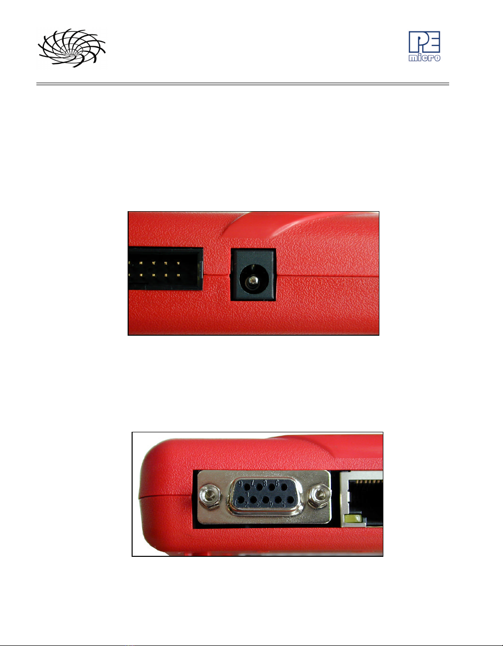
3.1 Power Source.................................................................................................6
3.2 Serial (RS232) Communications Port ............................................................6
3.3 USB 1.1 Communications Port.......................................................................7
3.4 Ethernet Communications Port ......................................................................7
3.5 PORT A – ColdFire V1 Core ..........................................................................8
3.6 PORT B – PowerPC Nexus Interface.............................................................9
3.7 PORT C – ColdFire Interface & ColdFire Extension Cable..........................11
3.8 PORT D – PowerPC Interface......................................................................14
3.9 PORT E – ARM Nexus.................................................................................15
3.10 PORT F – Reserved.....................................................................................16
3.11 Expansion Port (CompactFlash) ..................................................................16
3.12 Cyclone MAX Buttons ..................................................................................17
3.13 LEDs.............................................................................................................17
3.14 Ribbon Cable with IDC Socket.....................................................................17
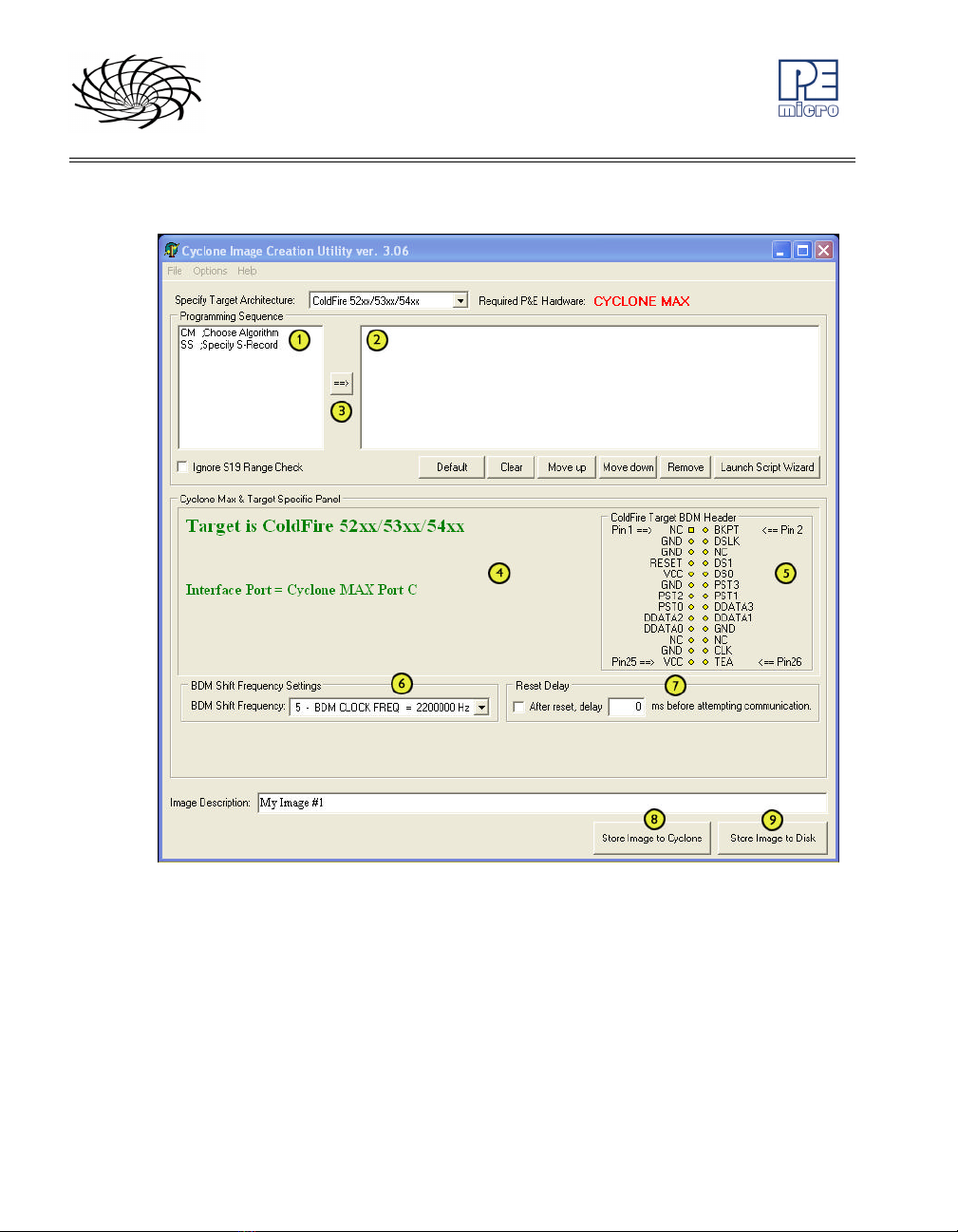
4STAND-ALONE PROGRAMMER CONFIGURATION.................................. 20
4.1 Target Architectures.....................................................................................21
4.2 BDM Shift Clock Delay Constant..................................................................26
4.3 Specify Programming Algorithm and S-Record............................................26
4.4 Base Address...............................................................................................26
4.5 Script Wizard................................................................................................26
4.6 Programming Operations.............................................................................29
4.7 Store Image To Cyclone...............................................................................30
4.8 Save Image/Cyclone Configuration..............................................................31
4.9 Configuration Via LCD Menu........................................................................31
5STAND-ALONE PROGRAMMER MANUAL CONTROL ..............................39
5.1 Via Cyclone MAX Buttons ............................................................................39

ii Cyclone PRO User Manual
CYCLONE PRO
5.2 Operation Procedure via LCD Menu.............................................................40
6STAND ALONE PROGRAMMER AUTOMATED CONTROL....................... 43
6.1 Automated .EXE Control Of The Cyclone.....................................................43
6.2 Automated .DLL Control Of The Cyclone .....................................................46
6.3 Control Of Multiple Cyclone Units.................................................................55
7PC-HOSTED DEBUG/PROGRAMMING SOFTWARE................................. 57
7.1 Freescale Codewarrior .................................................................................57
7.2 P&E Microcomputer Systems’ Software.......................................................61
8ETHERNET PORT CONFIGURATION ........................................................ 65
8.1 Network Architecture ....................................................................................65
8.2 Network Parameters.....................................................................................66
8.3 Internet Protocol ...........................................................................................66
8.4 Connecting the Cyclone Device....................................................................67
8.5 Cyclone IP Setup Via LCD Menu..................................................................69
8.6 Cyclone IP Setup Utility User Interface (ConfigureIP) ..................................69
8.7 Using IPSetup.exe to configure the Cyclone Max ........................................71
8.8 Managing Multiple Images............................................................................73
9SERIAL PORT CONFIGURATION............................................................... 75
10 USB PORT CONFIGURATION .................................................................... 76

Cyclone MAX User Manual 1
CYCLONE MAX
1INTRODUCTION
The Cyclone MAX is a versatile tool that can be used for the programming,
debugging, and testing of microprocessor-based hardware. It can be
controlled interactively via a Host PC, or operate independently of the PC in
stand-alone mode. The Cyclone MAX can also be configured and operated
via Serial, USB, and Ethernet communication interfaces. When in stand-alone
mode, its programming functions can be initiated directly through user input
buttons, or by using those same buttons to make selections from the LCD
menu.
The Cyclone MAX is able to debug and program a variety of processor
architectures using the target hardware’s Background Debug Mode (BDM) or
JTAG ports.
• Supported Architectures
•PowerPC (MPC5xx/MPC8xx)
•PowerPC Nexus (MPC55xx)
•ColdFire (MCF5xxx)
•ARM (MAC7xxx Automotive Family)
In addition to the versatility of being able to debug and program the
aforementioned processor families, and the ability to function in stand-alone
mode, the Cyclone MAX includes these other features:
• Multiple Communications Interfaces
•Ethernet 10/100 baseT
•USB 1.1
•Serial Baud 115200, no parity, 8 data bits, 1 stop bit.
• Onboard Storage
•Onboard storage of 7 Megabytes. Stores the image to be
programmed, programming algorithm, and any configuration settings.

2Cyclone MAX User Manual
CYCLONE MAX
•Multiple images may be saved using the onboard storage.
• Multi-Voltage Operation
•Automatically detects and caters to target voltages ranging from 1.8
to 5 Volts.
• LCD Menu
•Allows simple, menu-based control of the configuration and function
of the Cyclone MAX.
In short, the Cyclone MAX is an all-in-one solution for debugging,
programming, and testing of your hardware.

Cyclone MAX User Manual 3
CYCLONE MAX
2GETTING STARTED
Stand-alone programming is probably the most common use of the Cyclone
MAX, therefore this section provides a simple quick-start guide to 1)
configuring the Cyclone MAX with data, and 2) using it in stand-alone mode to
program the flash of a target system. The user is encouraged to read this
manual in its entirety for a complete description of the full feature set of the
Cyclone MAX.
2.1 Software Installation
The first step is to install the accompanying software. This will install all of the
applications and drivers that will be used to configure/control the Cyclone
MAX. Once the installation is complete and the PC has been rebooted you
may begin to configure the unit for operation.
2.2 Overview Of Cyclone MAX Configuration Utility
If you plan to use the Serial or USB ports for communication, then the
Cyclone MAX can be used right out of the box. If you wish to use the Ethernet
port, however, you will need to configure the corresponding IP numbers
before use. The Ethernet port will not be functional until this configuration is
complete. Please read Section 8 - ETHERNET PORT CONFIGURATION for
more information about the Cyclone IP Setup Utility.
Once you have connected the Cyclone MAX to the PC via either a Serial or a
USB cable, you can launch the Cyclone MAX Configuration Utility
(CreateImage.exe) application:

4Cyclone MAX User Manual
CYCLONE MAX
Figure 2-1: Cyclone Image Creation Utility
(1) Provides a list of available functions that the user may select and add
to the programming sequence.
(2) This window is where the programming steps are sequenced.
(3) This button moves selected programming functions into the sequence
window.
(4) Displays the processor architecture and the corresponding interface

Cyclone MAX User Manual 5
CYCLONE MAX
port on the Cyclone MAX.
(5) Displays the pinout configuration for the selected architecture.
(6) Allows the user to set the BDM Shift Frequency by selecting from the
drop-down box.
(7) Allows the user to set the Reset Delay.
(8) The “Store Image To Cyclone” button allows the user to store the
current image on the Cyclone MAX.
(9) The “Store Image To Disk” button allows the user to store the current
image on their hard drive. The Manage Image Utility can be used to
configure the Cyclone with one or more images.
At this stage you are simply configuring the Cyclone Max with the appropriate
data file and programming procedure. Actual programming of the target
hardware occurs later.
Once the information required in Areas 1-4 is complete, you may configure
the Cyclone Max by clicking the “Store Image to Cyclone MAX” button. Figure
2-1 indicates that this will be performed over the USB Port, USB1, as
displayed in Area 4. You may also select the Serial port, or the Ethernet port if
it has been configured appropriately.
After the image has been saved to the Cyclone Max, you can program a
target by simply pressing the “Start” button on the Cyclone Max. This will
begin the sequence that was specified in Area 3 (in this example: erase,
blank check, program, verify programmed data).
The complete functionality of the Cyclone MAX and its accompanying utilities
is beyond the scope of this Getting Started section. Please read further to
learn more about the full feature set and operation of the Cyclone MAX. For a
detailed description of the Cyclone MAX Configuration Utility, please refer to
Section 4 - STAND-ALONE PROGRAMMER CONFIGURATION.

6Cyclone MAX User Manual
CYCLONE MAX
3CYCLONE MAX HARDWARE
This section describes the various ports and inputs of the Cyclone MAX.
3.1 Power Source
The Cyclone MAX requires a regulated 6V DC Center Positive power supply
with 2.5/5.5mm female plug. The Cyclone MAX receives its power from the
power jack located on the side of the unit.
Figure 3-1: Power Jack
3.2 Serial (RS232) Communications Port
The Cyclone MAX provides a DB9 Female connector for communication with
a host computer through the Serial (RS232) Port. Communication takes place
at a fixed baud rate of 115200 Baud, 8 Data bits, No Parity, and 1 Stop Bit.
Figure 3-2: Serial Port

Cyclone MAX User Manual 7
CYCLONE MAX
3.3 USB 1.1 Communications Port
The Cyclone MAX provides a USB connector for communicating with a PC via
the Universal Serial Bus port. The Cyclone MAX is a USB 1.1 compliant
device.
Figure 3-3: USB Port
3.4 Ethernet Communications Port
The Cyclone MAX provides a standard RJ45 socket for communication with a
host computer through the Ethernet Port. The Ethernet Port of the Cyclone
MAX is a 10/100 baseT port.
Figure 3-4: Ethernet Port

8Cyclone MAX User Manual
CYCLONE MAX
3.5 PORT A – ColdFire V1 Core
Port A is used to connect to the ColdFire V1 core family of microprocessors.
For the physical dimensions of the connector, please see Section 3.14 -
Ribbon Cable with IDC Socket.
Figure 3-5: Port A
ColdFire V1 Core Pinout
BKGD 1 2 GND
NC 3 4 RESET
NC 5 6 VDD

Cyclone MAX User Manual 9
CYCLONE MAX
3.6 PORT B – PowerPC Nexus Interface
Port B can be used to connect to PowerPC Nexus (MPC55xx) targets. For the
physical dimensions of the connector, please see Section 3.14 - Ribbon
Cable with IDC Socket.
Figure 3-6: Port B - PowerPC Nexus Interface
PowerPC Nexus Pinout
TDI 1 2 GND
TDO 3 4 GND
TCK 5 6 GND
NC 7 8 NC
RESET 9 10 TMS
VDDE7 11 12 GND
RDY 13 14 JCOMP
3.6.1 BERG14-to-MICTOR38 Optional Connector (PORT B)
P&E offers a 14-pin BERG to 38-pin MICTOR adapter, sold separately, that
may be used on Port B of the Cyclone MAX. The P&E part number is
BERG14-TO-MICTOR38.

10 Cyclone MAX User Manual
CYCLONE MAX
Figure 3-7: BERG14-TO-MICTOR38 Adapter (Sold Separately)

Cyclone MAX User Manual 11
CYCLONE MAX
3.7 PORT C – ColdFire Interface & ColdFire Extension Cable
Port C is the interface for the ColdFire MCF52xx/53xx/54xx family of
microprocessors. This port connects to the target hardware using either the
ColdFire extension cable (for synchronous ColdFire targets) or a standard 26-
pin ribbon cable (for asynchronous ColdFire targets). Both cables are
provided in the Cyclone MAX package. Please refer to each processor’s user
manual to identify whether it is a synchronous or asynchronous interface. If
you are not sure, or for test purposes, the synchronous cable will work with all
52xx, 53xx, and 54xx targets. For the physical dimensions of the connector,
please see Section 3.14 - Ribbon Cable with IDC Socket.
Figure 3-8: Port C - ColdFire Interface

12 Cyclone MAX User Manual
CYCLONE MAX
ColdFire Pinout
N/C 1 2 BKPT
GND 3 4 DSCLK
GND 5 6 N/C
RESET 7 8 DSI
VCC 910 DSO
GND 11 12 PST3
PST2 13 14 PST1
PST0 15 16 DDATA3
DDATA2 17 18 DDATA1
DDATA0 19 20 GND
N/C 21 22 N/C
GND 23 24 CLK
VCC 25 26 TEA
The ColdFire extension cables, one for Synchronous targets and one for
Asynchronous targets, are pictured below:
Figure 3-9: ColdFire Extension Cable With Adapter (Synchronous ColdFire
Targets)

Cyclone MAX User Manual 13
CYCLONE MAX
Figure 3-10: ColdFire Ribbon Cable (Asynchronous ColdFire Targets)

14 Cyclone MAX User Manual
CYCLONE MAX
3.8 PORT D – PowerPC Interface
Port D can be used to connect to PowerPC BDM (5xx/8xx) targets. For the
physical dimensions of the connector, please see Section 3.14 - Ribbon
Cable with IDC Socket.
Figure 3-11: Port D - PowerPC Interface
PowerPC Pinout
N/C 1 2 SRESET#
GND 3 4 DSCLK
GND 5 6 N/C
HRESET# 7 8 DSDI
VDD 910 DSDO

Cyclone MAX User Manual 15
CYCLONE MAX
3.9 PORT E – ARM Nexus
Port E can be used to connect to ARM (MAC7xxx) targets. For the physical
dimensions of the connector, please see Section 3.14 - Ribbon Cable with
IDC Socket.
Figure 3-12: Port E- ARM Nexus
ARM Nexus Pinout
TVCC 1 2 N/C
TRST# 3 4 GND
TDI 5 6 GND
TMS 7 8 GND
TCK 910 GND
N/C 11 12 GND
TDO 13 14 GND
RESET# 15 16 GND
N/C 17 18 GND
N/C 19 20 GND

16 Cyclone MAX User Manual
CYCLONE MAX
3.10 PORT F – Reserved
Port F is reserved for future use by P&E. Do not connect to this port.
Figure 3-13: Port F
3.11 Expansion Port (CompactFlash)
The CompactFlash Port is for future use by P&E. Do not use this port.
Figure 3-14: CompactFlash Port (Unimplemented)
Other manuals for Cyclone MAX
2
Table of contents
Other PEmicro Motherboard manuals