PENCO Clipper User manual

Clipper® Shelving
Assembly Instructions
General Instructions
1. Check the number of packages (parts) received against the bill of lading. If any shortages,
secure a “shortage notation” from the carrier and file a claim. Check material for damage.
If any is damaged, secure a “damaged notation” from the carrier and file a claim against
carrier.
2. When unpacking, arrange like parts together as close as possible to the area in hich they
are to be assembled.
3. Tools required are slotted scre driver and 7/16" and 1/2" socket renches to tighten bolts
and nuts.
4. Use the proper size bolts for each part. Use no more than the number of clips or bolts that
are allo ed for each part.
5. Read remainder of these instructions carefully before you proceed further. Familiarize
yourself ith all component names.
6. Carefully lay out shelving positions on floor (chalk line suggested).
7. No follo the detailed instructions step by step.
Clipper Shelving
Assembl Instructions
Part No. 08185
1A BOX POST (FRONT ONLY)
1B OFFSET ANGLE POST
1C SHELF
1D CLIPPER SHELF CLIP
IMPORTANT NOTE
Shelf clip must be seated properly
on posts by lightly tapping top of
clip into slots. See illustration.
1A
1B
1C
1D
1E 1F
1G
1H
1I
1J
1K
1E SIDE SWAY BRACE
1F BACK SWAY BRACE
1GSIDE PANEL
1H BACK PANEL
1I BACK PANEL CLIP
1J HI-PERFORMANCE® SHELF
1K CONVENTIONAL FLANGE SHELF
Parts CAUTION
It is the responsibility of
the persons assembling the
shelving to properly install all
components and hard are as
specified in these instructions
and any accompanying dra ings
for specific installations.
• Install all required Side and
Back S ay Braces
• Install Foot Plates and Shims
if required
• Tighten all hard are securely

1. Pre-Clip posts by installing Clipper Shelf Clips here the shelves ill be located and tap
them do n ard to engage the clip hook in the post (see page 1).
2. End or intermediate side frame assemblies are made by connecting the required posts
ith side braces. Place the proper front and rear post on the floor (or table) parallel to
each other and spaced apart to match the depth of the unit you are building. Place
braces on the inside of the post approximately at midpoint of the height of the unit.
Select the proper brace, bolt together at the center using a 1/4”-20 x 1/2” truss head bolt
and hex nut to form an “X”. Bolt the brace to the side of the rear flanges of posts ith
four 1/4"-20 x 1/2" truss head bolts and hex nuts.
3. Stand t o assemblies upright. Move them into position and set a shelf into the top and
into the bottom sets of pre-clipped shelf clips. Press each shelf do n ard so that it is
seated on each of the four clips. Repeat this procedure ith the intermediate shelves.
4. Select the proper back brace, bolt together at the center using a 1/4”-20 x 1/2” truss
head bolt and hex nut to form an “X”. Attach the back s ay braces to the rear flanges of
offset angle post ith four 1/4"-20 x 1/2" bolts and nuts. Place the bottom holes of the
brace 3” to 6” of the floor. For an adjacent unit it is recommended that bracing be
staggered up and do n (see illustration above).
5. If double ro , assemble the front ro as above, then assemble the rear ro the same
as above, except use a common pair of back braces placed inside the posts of one unit
and tie the ro s together using the same bolts and nuts used on back braces.
Clipper Open Shelving
Assembly Instructions
PARTS DESCRIPTION
2A OFFSET ANGLE POST AT REAR
2B BOX POST (FRONT ONLY)
2C OFFSET ANGLE POSTS AT FRONT
2D SIDE SWAY BRACE
2E TWO OFFSET ANGLE POSTS AT REAR
2F BACK SWAY BRACE
2GTWO OFFSET ANGLE POSTS IF USED AT
FRONT
TWO OPEN UNITS
END UPRIGHT ASSEMBLY
INTERMEDIATE UPRIGHT ASSEMBLY
2A
2B
2C
2D
2F
2G
2
2E

1. Pre-Clip posts by installing Clipper Shelf Clips here the shelves ill be located
(see page 1).
2. Assemble end and intermediate side panel assemblies. Slip the panel be-
t een the flanges of the box post and on the inside of the flange on the back
post. Intermediate side panels must be placed bet een the flanges of the
back posts. Bolt the assemblies together using 1/4 “-20 x 1/2" bolts and nuts
through the first hole from each end. Bolt panels to the post approximately
every 12” (30 cm). On end panel assemblies bolt some additional locations to
hold the panel against the angle post.
3. Stand panels upright. Move the t o panels into position and set a shelf into
the top and into the bottom sets of pre-clipped shelf clips. Press each shelf
do n ard so it is seated on each of the four clips. Repeat this procedure ith
the intermediate shelves.
4. When assembling back panels, slide one edge of the back panel bet een the
inside flange of the angle post and the shelf, then slide the back bet een the
post flange and shelf on the other side. Line up the holes in the back panel
ith holes in the post and bolt the back panel to the angle post using 1/4”-20 x
1/2" bolts and nuts using approximately the same spacing as used in bolting
side panel to the post. Attach back to shelf clips as required to hold the back
to the shelves.
5. If double ro , assemble the front ro as above - but do not bolt the back
panel. Assemble the rear ro the same as above, omitting the back panel.
Push the units together and bolt through the t o angle posts and the back
panel using 1/4"-20 x 1/2" bolts and nuts at three places.
Clipper Closed Shelving
Assembly Instructions
Unit above sho n
ith optional
front base
PARTS DESCRIPTION
3A OFFSET ANGLE POST AT REAR
3B BOX POST (FRONT ONLY)
3C OFFSET ANGLE POSTS AT FRONT
3D SIDE PANEL
3E TWO OFFSET ANGLE POSTS AT REAR
3F BACK PANEL
3GTWO OFFSET ANGLE POSTS AT FRONT
END UPRIGHT ASSEMBLY
INTERMEDIATE
UPRIGHT ASSEMBLY
3A
3B
3C
3D
3F
3G
3

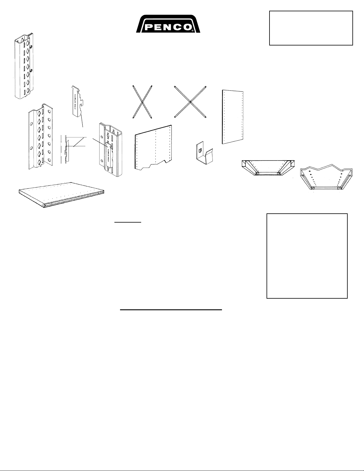
4A. Bin Fronts for box post. – 1" and 2" high bin fronts attach to the front of the
shelf ith 1/4-20 x 1-1/4” bolts & nuts. 3" high ill require bin front clips on each side.
Seat clips into side slots of post and insert bin front.
4B. Front Base – Fastens to bottom shelf ith 1/4-20 x 1-1/4” bolts & nuts. When
used ith offset angle posts in the front, the ends of front base slide bet een the
shelf and post.
4C. Label Holder – Attaches to front flange of shelf ith plastic button fasteners.
4D. Shelf Divider – Assemble so bead is facing to ard front. Engage plastic button
fasteners through divider and shelf holes. Each fastener ill serve for t o dividers
hen arranged one directly above the other.
4E. Box Guide – For use ith optional shelf boxes. Attaches to front post only ith
1/4-20 x 1-1/4” bolts and nuts. T o required per shelf.
4F. Floor Anchor Clip – Fastens to the rear flange of posts ith 1/4”-20 x 3/4” truss
head bolts and hex nuts. If required bolt the vertical tab to each box post, or a single
angle post or a double angle post.
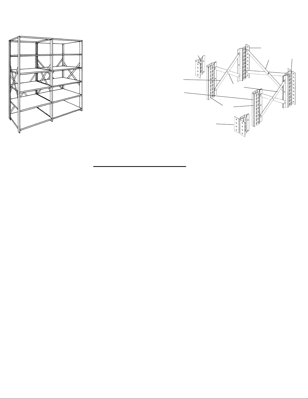
4G. Side Shelf Support – Bolts to the front and rear post ith 5/16”-18 x 1-1/4”
truss head bolts and hex nuts. Use t o bolts and nuts per support. Assemble ith
the flange at the top of the support. Support Flange faces to ard the inside of the
unit.
4H Class 3 Shelf Support – Place on the side shelf support under the shelf running
left to right approx. mid ay front to rear ith the flange ends against the bottom of
the shelf. Place the shelf ith the support on top of the side shelf support and en-
gage the support in the side shelf support notch.
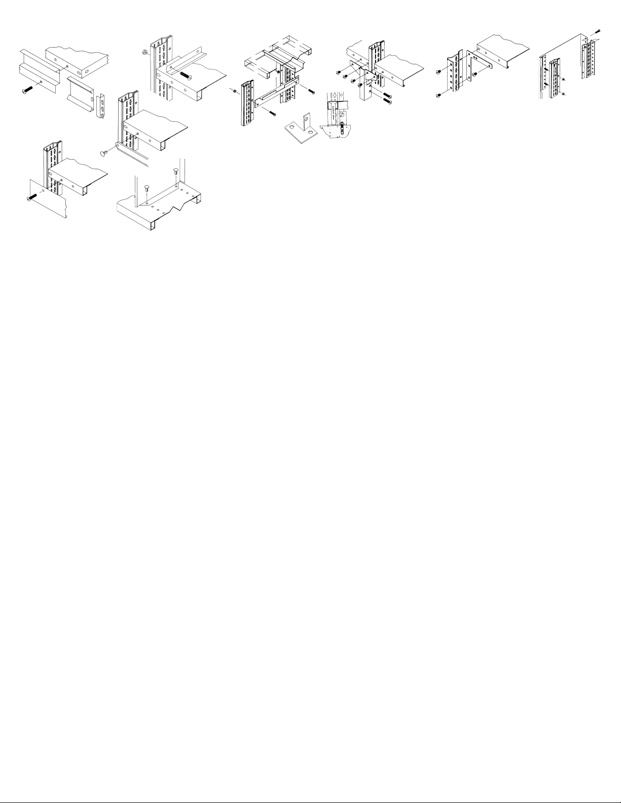
4I. Corner Angle Braces – For use with box posts and conventional flange
shelves. Place the brace over the box post and bolt ith 5/16”-18 x 1-1/4” truss head
bolt and finished hex nut. Bolt left and right flanges to respective shelves. Use t o
1/4”-20 x 1/2” pan head machine scre s and hex nuts per flange.
4J. Corner Angle Braces – For angle posts. Place the brace bet een the angle
post and the shelf. Bolt the brace to the post ith t o 1/4”-20 x 1/2” truss head bolts
and hex nuts. Bolt to the shelf ith one 1/4”- 20 x 1/2” truss head bolts and hex nuts.
For all bolts use the holes that align and are farthest from the brace corner.
4K. Finished End Panel – All fasteners furnished are 1/4”-20 x 1-1/4” truss head
bolts and nuts. Bolt the three “Z” shaped clips (Part No. 18100) to the body of the
box post near the top & bottom and in the middle. Slip the return flange of the end
panel under the “Z” clip and place the rear flange behind the post. Bolt the rear
flange to the post near the top, bottom and middle.
Clipper Shelving Assembly Instructions Part No. 08185pdf\cliprin.pdf Revised 3/03 Printed in U. S. A.
4A
4B
4C
4D
4E
4F
4G
4H 4I
4J 4K
Clipper Shelving
Accessories
Other PENCO Indoor Furnishing manuals
Popular Indoor Furnishing manuals by other brands

Whittier Wood Furniture
Whittier Wood Furniture Pacific Queen 1448AFCAF Assembly instructions

fantastic furniture
fantastic furniture Cody Desk Student 2 Drawer manual

Powell
Powell 987-481 Assembly instructions

Insignia
Insignia NS-ODL3 user guide

Monarch Specialties
Monarch Specialties I 7159 Assembly instructions

TIMBER ART DESIGN
TIMBER ART DESIGN Sen 02 Assembly instructions

Coaster
Coaster Mina 193762 Assembly instructions

SOMFY
SOMFY 152134 How to operate

realspace
realspace Broadstreet Controlled U-Shaped Desk Assembly instructions and warranty information

Amart Furniture
Amart Furniture 50299 Assembly instruction

Coaster
Coaster 460563T Assembly instructions

Nucraft
Nucraft Approach installation instructions