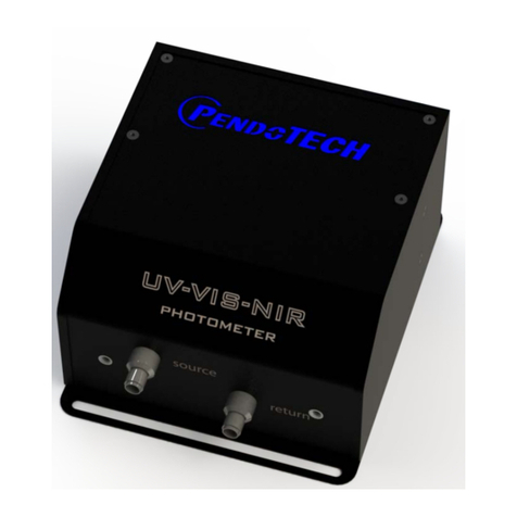
PendoTECH PM2 User manual

www.pendotech.com Tel: +1-609-799-2299
Copyright © 2022 PendoTECH
PENDOTECH® PM2
PHOTOMETER FOR UV/VIS
ABSORBANCE AND TURBIDITY
MEASUREMENTS
USER’S MANUAL

PendoTECH PM2 Photometer for UV Absorbance and Turbidity
Measurements User’s Manual Revision 0
www.pendotech.com Tel: +1-609-799-2299
Copyright © 2022 PendoTECH 1 | Page
Safety Instructions
Definition of Equipment and Documentation Symbols and Designations
WARNING: POTENTIAL FOR PERSONAL INJURY
CAUTION: Possible instrument damage or malfunction
NOTE: Important operating information
On the transmitter or in this manual text indicates Caution and/or other possible hazards, including the risk of electric
shock (refer to accompanying documents).
Each prospective user must test the measurement unit for its proposed application to determine its suitability for
the purpose intended prior to incorporating the sensor to any process or application. Proper safeguards must be
put into place for the process in which the unit is used.
The functioning and operational safety of the product can only be ensured if the user observes the usual safety
precautions as well as the specific safety guidelines stated in these operating guidelines:
The PM2 Photometer must only be operated under
the specified operating conditions.
The PM2 Photometer should be installed and
operated only by personnel familiar with the
Photometer and who are qualified for such work.
Before connecting the device to a supply unit, ensure
its output voltage cannot exceed 48 VDC. Do not use
alternating current or a main power supply!
Warning: Only use a power supply with double
insulation or reinforced insulation to supply this
product.
Warning: Do not submerge this product. Protect the
product before cleaning with any liquids by covering
openings that expose the internal components.
Install equipment as specified in this instruction
manual. Follow appropriate local and national codes.
Power supply must be disconnected before servicing.
The safety of the user may be endangered if the
instrument:
•is visibly damaged
•no longer operates as specified
•has been damaged in transport
Process upsets: because process and safety
conditions may depend on the consistent operation
of this transmitter, provide appropriate means to
maintain operation during sensor cleaning,
replacement, or sensor or instrument calibration.
Except for routine maintenance and cleaning procedures,
the PM2 Photometer must not be tampered with or altered
in any manner.
Maintenance and repair work must only be carried out by
PendoTECH.
METTLER TOLEDO/PendoTECH accepts no
responsibility for damage caused by unauthorized
modifications to the Photometer.
Follow all warnings, cautions, and instructions indicated
on and supplied with this product.
Electrical installation must be per the National Electrical
Code and/or any other applicable national or local codes.
If this equipment is used in a manner not specified by the
manufacturer, its protection against hazards may be
impaired.
Relay action: the PM2 Photometer relays will always de-
energize on the loss of power, equivalent to a normal
state, regardless of the relay state setting for powered
operation. Configure any control system using these
relays with fail-safe logic accordingly.
The terminals are suitable for single wires / flexible leads
0.2 mm2 to 1.5 mm2 (AWG 16 – 24).

PendoTECH PM2 Photometer for UV Absorbance and Turbidity
Measurements User’s Manual Revision 0
www.pendotech.com Tel: +1-609-799-2299
Copyright © 2022 PendoTECH 2 | Page
Optical Safety
Warning: The photometer can emit light in the range
of 200 nm – 1100 nm. Hazardous UV and IR
radiation are emitted from the unit. Never directly
stare into the source/return ports on the photometer
or the fiber optic cables, as this can cause eye
damage. The viewer-related risk depends on how the
users install and use the product.
The photometer should always be powered off when
handling the fiber optic cables. Protective eyewear
must be worn if you must handle the fibers when the
unit is powered on.
Ensure that both ends of the fiber optic cables
(photometer and flow cell connections) are properly
secured (firmly hand-tight) before powering on the
photometer.
In the event of product failure, do not attempt to open the
unit or replace the LED. There are no user-serviceable
parts.
Fig 1: Warning label, PM2, Fiber cable.

PendoTECH PM2 Photometer for UV Absorbance and Turbidity
Measurements User’s Manual Revision 0
www.pendotech.com Tel: +1-609-799-2299
Copyright © 2022 PendoTECH 3 | Page
Contents
Safety Instructions.................................................................................................................................................................. 1
1 Disclaimer ............................................................................................................................................................................ 4
2 Introduction and Unpacking ............................................................................................................................................... 4
2.1 Identify the following components............................................................................................................................... 4
3 Flow Cell and Flow Cell Stand ............................................................................................................................................. 5
3.1 Flow Cells ...................................................................................................................................................................... 5
3.2 Optical Couplers............................................................................................................................................................ 5
4 Unit Overview...................................................................................................................................................................... 6
5 Hardware installation.......................................................................................................................................................... 7
5.1 Environmental............................................................................................................................................................... 7
5.2 Physical.......................................................................................................................................................................... 7
5.3 Panel Display and Buttons ............................................................................................................................................ 7
............................................................................................................................................................................................ 7
5.4 Alarms ........................................................................................................................................................................... 8
5.5 Configuration of Unit for Laboratory or Panel Mount Installations ............................................................................. 9
5.6 Optical ........................................................................................................................................................................... 9
5.7 Electrical...................................................................................................................................................................... 10
6 Introduction to Absorbance Monitoring .......................................................................................................................... 11
6.1 Theory of Operation.................................................................................................................................................... 11
6.2 LED-Based Absorbance ............................................................................................................................................... 12
7 Glossary and definitions.................................................................................................................................................... 13
8 Instrument Control............................................................................................................................................................ 14
8.1 Zero ....................................................................................................................................................................... 14
9 Absorbance Operations ..................................................................................................................................................... 14
10 System Specification ....................................................................................................................................................... 15
10.1 Optical Configuration................................................................................................................................................ 15
10.2 PM2 Specifications.................................................................................................................................................... 15
10.3 Service Information................................................................................................................................................... 15

PendoTECH PM2 Photometer for UV Absorbance and Turbidity
Measurements User’s Manual Revision 0
www.pendotech.com Tel: +1-609-799-2299
Copyright © 2022 PendoTECH 4 | Page
1 Disclaimer
All rights reserved. No part of this publication may be reproduced, stored in an electronic retrieval system, or transmitted
in any form or by any means, whether electronic, mechanical, by photocopying or otherwise, without the written consent of
PendoTECH.
The information in this User Guide is believed to be accurate and reliable for the use and operation of the monitor;
however, PendoTECH assumes no responsibility for the use of this product except for what is covered in the Limited
Warranty and Terms and Conditions of Sale.
NOTE: “NOTE” is used to notify the user of installation or operation information that is important but not hazard-related.
2 Introduction and Unpacking
The PendoTECH UV PM2 Photometer is a versatile measuring and monitoring device that allows users to measure
absorbance and turbidity in bioprocess fluid streams. The device uses a collimated beam of light that passes through a
sample with a defined path length to determine the absorbance of the sample. The photometer can measure UV
absorbance at 260nm, 280nm, or 300nm to identify the presence or absence of a molecule of interest and at 880nm to
measure turbidity and filter performance.
The photometer also functions as a transmitter with a 4-20mA output scaled 0-3 AU, making it easy to integrate with other
monitoring and control systems. The photometer is available in a dual-wavelength version, which allows users to make
two measurements of multiple wavelengths simultaneously in the same sample.
To make measurements in-line, the photometer uses PendoTECH Single Use UV/Turbidity Flow Cells, which contain a
special silica glass lens and compartments for optical couplers. The flow cells can be repeatedly cleaned and reused but
are designed for single use. PendoTECH Flow Cell Stand is an accessory that can be used to house or mount these flow
cells as an alternative to optical couplers. The stand is recommended for improved usability and accessibility when
changing flow cells and for blocking out ambient light in turbidity applications.
Overall, the PendoTECH UV PM2 Photometer and Single Use Flow Cells provide a reliable and convenient solution for
measuring and monitoring bioprocess fluid streams.
2.1 Identify the following components
Note: All the parts listed below are to be ordered individually.
Photometer
PM2
Flow cell Large Stand Flow cell Small Stand
Calibration Kit
Coupler(s)
Fiber Optic Cable

PendoTECH PM2 Photometer for UV Absorbance and Turbidity
Measurements User’s Manual Revision 0
www.pendotech.com Tel: +1-609-799-2299
Copyright © 2022 PendoTECH 5 | Page
3 Flow Cell and Flow Cell Stand
Note: For Turbidity, a Flow Cell stand is required to block ambient light at 880nm from interfering with the measurement
3.1 Flow Cells
The combination of the UV PM2 photometer and the PendoTECH Single Use Flow Cells allows the measurements to be
made in line. The flow cells contain a special silica glass window and compartments to insert optical couplers, which
attach to the fiber optic cables from the photometer. The flow cells can also be used with PendoTECH’s Flow Cell Stand
with integral couplers in place of the optical couplers to connect the fiber optic cables. The flow cell stand is optional but
recommended because it blocks out ambient light that could otherwise affect the absorbance readings. Additionally, the
flow cell stand improves accessibility and makes it easier to change flow cells. Although designed for single use, the flow
cells may be repeatedly cleaned and reused.
3.2 Optical Couplers
SMA905 connectors of the
connection of the fiber optics
Flow Cell stand cover to secure
the flow cell and blocks ambient
light
Flow Cell stand for 6.5cm flow cell
Material #: 30849504
Flow Cell stand for 1cm flow cell
Material #: 30849505
6.5cm Single-Use Turbidity Clow
Cell
Flow Cell with tubing installed
Optical Couplers installed to the
Flow Cell

PendoTECH PM2 Photometer for UV Absorbance and Turbidity
Measurements User’s Manual Revision 0
www.pendotech.com Tel: +1-609-799-2299
Copyright © 2022 PendoTECH 6 | Page
4 Unit Overview
Note: For single channel units, only pins 1 and 2 are used. For dual channel units, pins 1 and 2 correspond to the photometer’s first
wavelength (lower), and pins 3 and 4 correspond to the second wavelength (higher).
1
4-20 mA +
6
RS485-A
11
ZERO -
2
4-20 mA -
7
RS485-B
12
ALARM +
3
4-20 mA +
8
GND
13
ALARM -
4
4-20 mA -
9
12-48 VDC
POWER
4-20 mA = 0-3 AU
5
RS485 Shield
10
ZERO +
Fig 2: PM2 (Photometer) dimensions in mm.

PendoTECH PM2 Photometer for UV Absorbance and Turbidity
Measurements User’s Manual Revision 0
www.pendotech.com Tel: +1-609-799-2299
Copyright © 2022 PendoTECH 7 | Page
5 Hardware installation
Please follow the outlined sections below as a guideline for installing the photometer and associated accessories. These
guidelines apply for specific application installations or, in the case of OEM component installation onto a suitable panel.
5.1 Environmental
The photometer is strongly recommended to be installed in a clean, dry area where the ambient temperature does not
exceed 115F/46C. Systems mounted in enclosures can be purged with clean, dry, oil-free air (or nitrogen) to dissipate
heat.
5.2 Physical
For permanent installations
Bolt the photometer, back panel, or enclosure (as appropriate) in place using mounting screws. The location should be
secure, rigid, and strong enough to support the weight of the installed system.
For laboratory use
Ensure sufficient space on the bench or tabletop to accommodate the hardware supplied.
For panel mount use
Ensure sufficient space on the bench or tabletop to accommodate the hardware supplied.
For all installations
Run the fiber optic cable(s) through conduit or other appropriate protective measures as desired. Refer to Section 5.3
below for optical component installation instructions.
Run required electrical wiring for instrument power and output signals (4-20mA). Review Section 5.4 below before making
electrical connections.
5.3 Panel Display and Buttons
DO NOT SUPPLY POWER TO THE UNIT UNTIL TOLD TO DO SO IN THE INSTRUMENT SETUP
AND INITIALIZATION PROCEDURE IN SECTION 5
Reporting the current
measured absorbance in
Absorbance Units [AU].
Wavelength of the used
LED displayed.
Overall status of the device. During
error-free operation, the textbox will
state “OK” on a green background.
This status is shown when a “Tare”
button is pressed for 5
seconds. Once it is tared, the
absorbance will be set to 0.00 AU.
Display
Wakeup/Backlight
On.
Tare button

PendoTECH PM2 Photometer for UV Absorbance and Turbidity
Measurements User’s Manual Revision 0
www.pendotech.com Tel: +1-609-799-2299
Copyright © 2022 PendoTECH 8 | Page
5.4 Alarms
Refer to the PM2 photometer’s Display, indicating an alarm condition. For the 4-20mA outputs will indicate alarms (going to high-level).
Alarm Activator
Cause
Solution
The measurement detector is
saturated at 100%.
Photometer outputting invalid
absorbance values due to bad tare.
Re-tare flow cell with background
solution or air.
The reference detector is saturated
at 100%.
Extreme amount of ambient light
entering flow cell/measure detector.
Use flow cell holder to block ambient
light from entering flow cell; ensure
fiber optic cable connections are firmly
hand tight.
The reference light and dark signals
are too close to each other.
LED is dead.
Send back to PendoTECH for repair.
On errors the device enters the
alarm mode. (See section alarms).
The screen signals -NA- (Not
applicable) on a red background in
the [AU] textbox.
The status textbox states “ALARM”
and changes background to red.
Reporting the current measured absorbance
in Absorbance Units [AU]. Left side for
channel 1 right side for channel 2.
Wavelength(s) of the used
LED displayed.
Overall status of the device. During
error-free operation, the textbox will
state “OK” on a green background.
This status is shown when a “Tare”
button is pressed for 5
seconds. Once tared, set the
absorbance to 0.00 AU for both
channels.
The screen signals -NA- (Not
applicable) on a red background in
the affected AU channels.
The status textbox states “ALARM”
and changes background to red.

PendoTECH PM2 Photometer for UV Absorbance and Turbidity
Measurements User’s Manual Revision 0
www.pendotech.com Tel: +1-609-799-2299
Copyright © 2022 PendoTECH 9 | Page
5.5 Configuration of Unit for Laboratory or Panel Mount Installations
PM2 has dual functionality to operate as a laboratory benchtop unit or panel mount unit. By default the configuration
switch is in the Lposition or laboratory unit. In this configuration the power connector and the 8-pin circular input/output
connector are active. To change to the panel mount configuration where power, input/output functions are on the screw
terminal connector, move the switch to the Pposition as shown.
5.6 Optical
1. Remove the protective caps from the SMA-905 connectors on the fiber optic cables and the photometer.
2. Clean the fiber ends with spectroscopic-grade isopropyl alcohol (IPA, also known as 2-propanol) or methanol
using a lint-free cotton swab or non-abrasive task wipe. Spectroscopic grade acetone can also be used, but
separation of cotton from the swab might occur as the binding agent dissolves.
3. Properly mount the flow cell stand/holder (if applicable to system). The flow cell stand can be set directly flat on
a lab bench or should be properly wall/panel mounted. Proper mounting of the flow cell stand facilitates the
pass through of bubbles/air pockets in the fluid stream, which if trapped in the flow cell, can degrade system
performance.
Fiber optic connections
Fig 4: Complete system setup showing measure unit/PM 2
Photometer, flow cell stand/holder, and fiber optic cables
Fig 3: Front view of the PM2 Photometer with fiber optic cables for
source and return.
Flow Cell
Flow Cell
Stand
Fiber Optic
cables

PendoTECH PM2 Photometer for UV Absorbance and Turbidity
Measurements User’s Manual Revision 0
www.pendotech.com Tel: +1-609-799-2299
Copyright © 2022 PendoTECH 10 | Page
30849504 Panel Mounting
30849505 Panel Mounting
4. Connect the flow cell with optical couplers or flow cell stand to the photometer with the fiber optic cables. It does
not matter which fiber connects to the source and return.
NOTE: Ensure that both ends of the fiber optic cables (photometer and flow cell connections) are properly secured
(firmly hand tight) before powering on the photometer.
5. Power on the unit. Refer to section 5.7 below for electrical connection and wiring.
6. Press the tare button (or perform dry contact closure over Tare/Zero +/- pins). This initiates the taring routine.
NOTE: For best results, the unit should be tared with the process background fluid in the flow cell if possible. If not
possible, then a tare with air in the flow cell may be used instead.
7. Wait at least 3 seconds for the taring routine to complete.
NOTE:In a panel mount installation, the display is not visible. It is recommended to integrate a 3s indication display
on the user interface that the unit is not ready for use (do not change fluid sate in the flow cells light path).
8. The unit is now ready for operation.
5.7 Electrical
Panel mount version
NOTE: For single channel units, only pins 1 and 2 are used. For dual channel units, pins 1 and 2 correspond to the photometer’s first
wavelength (lower), and pins 3 and 4 correspond to the second wavelength (higher).
1
4-20 mA +
6
RS485-A
11
ZERO -
2
4-20 mA -
7
RS485-B
12
ALARM +
3
4-20 mA +
8
GND
13
ALARM -
4
4-20 mA -
9
12-48 VDC POWER
4-20 mA = 0-3 AU
5
RS485 Shield
10
ZERO +
NOTE:The fiber optic cables must be secured so they are not free to move around, be
stepped on, leaned against, or otherwise damaged during normal operations. The minimum
bend radius for fibers UV PM2 Photometer is 8” (20.3cm).
Only hand tighten SMA-905 connections. Never use a wrench, pliers, or other tool. Over-
tightening the SMA-905 connections may result in damage to the connector and the fiber
optic cable, drastically reducing or prohibiting light transmission and requiring the
replacement of the fiber optic cables.
To change to the panel mount
configuration where power, input/output
functions are on the screw terminal
connector, move the switch to the P
position as shown.

PendoTECH PM2 Photometer for UV Absorbance and Turbidity
Measurements User’s Manual Revision 0
www.pendotech.com Tel: +1-609-799-2299
Copyright © 2022 PendoTECH 11 | Page
Lab version
I. Connect the power and ground to the system.
For laboratory systems, a 24VDC power brick is included with every PM2. However, the global use wall plug(s) must be
ordered separately.
For panel-mounted systems, a 13-position terminal block connector is on the back of the PM2.Use a small flathead
screwdriver to loosen the screw, insert a NON-ENGERGIZED 12-48VDC lead (with the end stripped so the metal wire is
exposed) to position 9, and tighten the screw to secure the lead. Repeat the same procedure for securing the grounding lead
to position 8.
II. Connect the 4-20mA output. For single-channel units, only pins 1 and 2 are used. For dual channel units, pins 1 and 2
correspond to the photometer’s first wavelength (lower), and pins 3 and 4 correspond to the second wavelength (higher).
Pin
8-pos
Pin Function
1
WH
4-20 mA +
2
BN
4-20 mA -
3
GN
4-20 mA +
4
YE
4-20 mA -
5
GY
RS485 Shield
6
PK
RS485-A
7
BU
RS485-B
8
RD
GND
PendoTECH also has other pre-configured cables for connections to the PendoTECH Pressure MAT® Plus monitors, PendoTECH
Control Systems, and other PendoTECH products.
6 Introduction to Absorbance Monitoring
6.1 Theory of Operation
Absorbance measures how much incident light is absorbed when it passes through a material. Light intensity decreases exponentially
with distance as light passes through the material, so transmittance can be determined by measuring the intensity of both the incident
and transmitted light. The value for transmittance can then be used to calculate the absorbance of the sample.
The Beer-Lambert Law relates how absorbance is related to the concentration and the distance the light must travel through the sample
(path length):
A= εcl
Where A is absorbance, ε is the extinction coefficient, c is the concentration of the solution (in mol/L), and l is the path length traveled
by light through the sample (in cm).
The default configuration switch is in the
Lposition or laboratory unit. However, if
the switch is in the panel mount
configuration, move the switch from P
position to Las shown.
NOTE: DO NOT power up the unit during installation. Ensure that all electrical connections
are made with un-energized wires. It is recommended that an ON/OFF switch be employed
for panel mounting.

PendoTECH PM2 Photometer for UV Absorbance and Turbidity
Measurements User’s Manual Revision 0
www.pendotech.com Tel: +1-609-799-2299
Copyright © 2022 PendoTECH 12 | Page
6.2 LED-Based Absorbance
Light emitting diode (LED)-based photometers are a desirable choice when qualitative measurements are desired. Additionally, using
calibration standards and environmental control, an LED-based photometer is capable of quantitative determination of analyte
concentration. When making quantitative measurements, it is critical that the LED-based photometer is accurately correlated to
standard laboratory methods and solutions.
The LED provides a specific wavelength (or wavelengths for dual channel models) range for measurement, selected to coincide with
analyte-specific molecular absorbance. The LED is located internal to the photometer and is specific to the application. Therefore, the
PM2 UV photometer is a dedicated instrument for monitoring only one or two specific analytes of interest.
Shown below are three example LED spectrum profiles graphs for typical LED light source wavelengths 260/280/300/880nm
(Figures 5-8).
Definitions
•CWL (Center Wavelength): The wavelength of an optical source that is considered its’ middle. The wavelength of the peak of
the spectral density curve.
oWatch-Out: If measurements are attempted on a shoulder/slope of the molecule’s absorption profile, the absorption
measurement can change dramatically over the span of a few nanometers. Absorbance may never saturate as a
portion of the LED’s output is outside of the molecule’s absorbance profile. Minute photometer unit-to-unit absorption
variations exist due to CWL tolerance.
•FWHM (Full Width Half Maximum): A measure of the range of light the LED generates. The width of an optical signal at half
its maximum intensity
oWatch-Out: If the light source FWHM width is wider than the molecule’s absorption peak, which will produce false,
low absorption values.
260nm LED
Fig 5: LED wavelength spectrum example for 260nm UV PM2 Photometer.
Fig 6: LED wavelength spectrum example for 280nm UV PM2 Photometer.
280nm LED

PendoTECH PM2 Photometer for UV Absorbance and Turbidity
Measurements User’s Manual Revision 0
www.pendotech.com Tel: +1-609-799-2299
Copyright © 2022 PendoTECH 13 | Page
In brief, the photometer works as follows: The measuring system is in the detector block of the photometer. Light is provided by an
LED, which produces a stable light output at a narrow wavelength range. The reference signal is measured directly from the light
source by the reference detector, and light that passes through the sample is measured by the measure detector. The reference
channel is used in order to cancel variations from light source intensity fluctuations, spectral change due to window fouling, or
suspended particles in the process stream.
7 Glossary and definitions
Dynamic Range: Dynamic range refers to the range of concentrations an instrument can read, from the minimum to the maximum
detectable concentration. The minimum detectable concentration is determined by the signal-to-noise ratio. The maximum detectable
concentration is determined by the compound’s chemistry and by factors such as instrument sensitivity ranges, optical pathlength, etc.
Linearity: Absorbance intensity is typically directly proportional (linear) to concentration. There are, however, many factors that affect
this linear relationship. For example, stray light, turbidity, variation in the chemical composition of the background, etc., can affect the
linearity of the absorbance response.
Measure Detector: A detector that measures the intensity of light after it has contacted the sample. The system is designed so that
only absorbing wavelengths of light are measured by the measure detector.
Measure LED: The measure LED is the light-emitting diode (LED) used to select the
measurement wavelength.
Measure Wavelength: The wavelength, or range of wavelengths, of light absorbed by the analyte(s) of interest.
Process Background: The liquid or gas used to transport or sustain the analyte of interest in the process. This includes all the
chemical constituents found in the process except the analyte of interest.
Reference LED: The reference LED is the light-emitting diode (LED) used to select the reference wavelength to be measured by the
reference detector. The centre wavelength selected is a wavelength at which the analyte of interest does not absorb and is used to
cancel variations from such effects as light source intensity fluctuations or spectral change due to window fouling or suspended
particles in the process stream. Reference LED is an optional feature but is required through media referencing.
Sensitivity: The ability of the photometer to detect a given level of analyte based on the molecular absorbance of the analyte. The
actual limits of detection depend on the properties of the analyte measured and the process conditions.
Specificity: The ability of the analyzer to monitor one specific analyte in a mixture of
background materials without interference from the background materials.
Fig 7: LED wavelength spectrum example for 300nm UV PM2 Photometer.
300nm LED
800nm LED
Fig 8: LED wavelength spectrum example for 800nm UV PM2 Photometer.

PendoTECH PM2 Photometer for UV Absorbance and Turbidity
Measurements User’s Manual Revision 0
www.pendotech.com Tel: +1-609-799-2299
Copyright © 2022 PendoTECH 14 | Page
8 Instrument Control
8.1 Zero
9 Absorbance Operations
This procedure assumes that the hardware has been installed correctly and is ready for operation. For panel-mounted systems, this
procedure is valid once electrical connectivity is established.
DO NOT power the unit until directed to do so in this procedure.
1. Ensure that the fiber optic connections to the photometer and the corresponding optical flow cell couplers are hand tight. See Section
5.5 for instructions
a. Insert single-use flow cell into the flow cell stand/holder (if applicable). Replace the stand’s cover and close the cover firmly
to securely hold the flow cell.
2. Ensure that both the power and the analog output connections are wired correctly. See Section 5.7 for instructions.
3. Provide power to the unit.
4. Zero (tare) the unit.
NOTE: For best results, the unit should be tared with the process background fluid in the flow cell if possible. A tare with air in the
flow cell may be used instead if not possible.
1
4-20 mA +
6
RS485-A
11
ZERO -
2
4-20 mA -
7
RS485-B
12
ALARM +
3
4-20 mA +
8
GND
13
ALARM -
4
4-20 mA -
9
12-48 VDC
POWER
4-20 mA = 0-3 AU
5
RS485 Shield
10
ZERO +
NOTE: For best results, the unit should be tared with the process
background fluid in the flow cell if possible. If not possible, then a
tare/calibration with air in the flow cell may be used instead.
NOTE: The 4-20mA output is correlated to absorbance intensity in AU
(absorbance units). The 4-20mA output must be scaled using an external
device to convert absorbance intensity to relevant engineering units. The
photometer cannot be set to relevant engineering units and has a fixed
range of 0.00-3.00AU = 4mA-20mA.
NOTE: Please reference Section 5 for hardware installation
instructions (environmental specifications, physical mounting,
optical connectivity, and electrical connectivity).

PendoTECH PM2 Photometer for UV Absorbance and Turbidity
Measurements User’s Manual Revision 0
www.pendotech.com Tel: +1-609-799-2299
Copyright © 2022 PendoTECH 15 | Page
10 System Specification
This section provides detailed specifications for the PM2 UV Photometer system purchased. In addition, this section may contain
application-specific notes on operability and functionality.
10.1 Optical Configuration
The optical configuration listed is for a complete analyzer system. The detectors and light-emitting diode (LED) are internal to the
photometer housing.
Optical Method
Absorbance
Light Source
LED
Reference Selection
Internal Source Reference
10.2 PM2 Specifications
Configuration
Internal Source Reference
Optical Connectivity
SMA-905
Mechanical
4” (10.2cm) W x 4” (10.2cm) L x 2.5” (6.4cm) H
Weight: ~1.9lbs.
Power Requirement
12 - 48VDC nominal, 10W max power
Max. supply voltage fluctuations
+10% of DC supply voltage
Overvoltage Category
Category I
Output
4-20mA (Active/sourcing) spanned 0-3AU
Analog Loop Resistance
500 ohms
Alarm Relay
Max. 48 VDC, Max. 1 A
Operating Temperature
41 to 122°F (5 to 50C)
Storage Temperature
-4 to 122°F (-20 to 50C)
Operating altitude
Max. 5000 m above sea level
Humidity
20-80% relative humidity, non-condensing
Measurement Range
0.00-3.00AU
Response Time
1 second
Accuracy*
0-2AU: ±1%FS (±0.03AU) ; 2-3AU: ±2%FS (±0.06AU)
Precision/Repeatability
±0.5% full scale (±0.015AU)
LED Lifetime
> 5 years
Available Wavelengths
240-1000 nm
Regulatory
RoHS3, REACH, CE, UKCA
When converting the 4-20mA output to Absorbance Units (AU):
Let x= 4-20mA output
4
16 × 3.000 =
10.3 Service Information
Any product which is under warranty must be returned to PendoTECH for repair. If out of warranty, the user should call PendoTECH for
over-the-phone assistance and our service staff will help determine if the unit should be returned for repair.
For factory service, please contact PendoTECH at request@pendotech.com or
call +1-609-799-2299 for a return authorization number.
Then pack the unit carefully, preferably in the original shipping container, insure it, and ship it to PendoTECH.
Table of contents
Other PendoTECH Measuring Instrument manuals
Popular Measuring Instrument manuals by other brands

DeFelsko
DeFelsko PosiTest HHD Verifier instruction manual

Extech Instruments
Extech Instruments 451112 user guide

Hanna Instruments
Hanna Instruments HI 99300 instruction manual

ICP DAS USA
ICP DAS USA iSN-713-MRTU quick start

Badger Meter
Badger Meter FC-5000 user manual

Cortalk
Cortalk RMU5 Generic Installation and configuration guide