Pengo SA-70 User manual

(M135776.indd) SA-70 1
Manual Number: M135776.indd
Release Date: March 27, 2007
AUGER DRIVE
(TWO SPEED GEARTEK MOTOR VARIANT)
SA-70 (660983)
800-599-0211 l www.paladinbrands.com l PENGO: 500 East Highway 10, Laurens, IA 50554, United States of America
Instruction Manual
Owner’s Manual
Safety Precautions
Operating Instructions
Maintenance
Parts Lists

2 SA-70 (M135776.indd)
Preface / Table of Contents ................................................................................................................................. 2
Safety Statements ............................................................................................................................................ 3
General Precautions ........................................................................................................................................... 4
Safety Decal Locations / Serial Tag Location ...................................................................................................... 5
Specications / Component and Control Locations ............................................................................................ 6
Set-Up Instructions / Operating Procedures / Storage ....................................................................................... 7
General Maintenance / Checking and Changing the Gear Oil ............................................................................ 8
Maintenance Cont. / Troubleshooting ................................................................................................................. 9
SA-70 Drive Parts Breakdown ........................................................................................................................... 10
SA-70 Drive Parts List ........................................................................................................................................11
Auger Drive Warranty Policy / Returned Goods Policy ..................................................................................... 12
Torque Chart for Common Bolt Sizes ................................................................................................................ 13
This manual is used to familiarize you with safety, assembly, operation, adjustment, troubleshooting, and maintenance.
Read and follow the recommendations in this manual to ensure safe and efcient operation. The information contained
in this manual was current at the time of printing. Some items may change slightly to assure you the customer, the best
performance.
We want you to be completely satised with your new product, feel free to contact your local Authorized Service Dealer for
help with service, replacement parts, or any other information you may require.
Whenever you contact your Authorized Service Dealer or the factory, always have the model number and serial number
of your product available. These numbers will help provide exact information about your specic product. You will nd the
model and serial numbers on an ID plate located on the product.
For your convenience, write the product model number, serial numbers, and date of purchase in the spaces below.
PREFACE
TABLE OF CONTENTS
MODEL NO: ___________________
SERIAL NO: ___________________
DATE of PURCHASE: _____________

(M135776.indd) SA-70 3
THIS STATEMENT IS USED WHERE SERIOUS INJURY OR DEATH WILL RESULT IF THE
INSTRUCTIONS ARE NOT FOLLOWED PROPERLY.
THIS STATEMENT IS USED WHERE SERIOUS INJURY OR DEATH COULD RESULT IF
THE INSTRUCTIONS ARE NOT FOLLOWED PROPERLY.
THIS STATEMENT IS USED WHERE MINOR INJURY COULD RESULT IF THE
INSTRUCTIONS ARE NOT FOLLOWED PROPERLY.
THIS SYMBOL BY ITSELF OR USED WITH A SAFETY SIGNAL WORD THROUGHOUT
THIS MANUAL IS USED TO CALL YOUR ATTENTION TO INSTRUCTIONS INVOLVING
YOUR PERSONAL SAFETY OR THE SAFETY OF OTHERS. FAILURE TO FOLLOW
THESE INSTRUCTIONS CAN RESULT IN INJURY OR DEATH.
READ MANUAL PRIOR TO INSTALL
Improper installation, operation, or maintenance of the equipment could result in serious
injury or death. Operators and maintenance personnel should read this manual as well as
all manuals related to this equipment. FOLLOW ALL SAFETY INSTRUCTIONS IN THIS
MANUAL.
READ AND UNDERSTAND ALL SAFETY STATEMENTS
Read all safety decals and safety statements in all manuals prior to operating or working
on this equipment. Know and obey all OSHA regulations, local laws and other professional
guidelines for your operation. Know and follow good work practices when assembling,
maintaining, repairing, mounting, removing or operating this equipment.
KNOW YOUR EQUIPMENT
Know your equipment’s capabilities, dimensions and operations before operating. Visually
inspect your equipment before you start, and never operate equipment that is not in proper
working order with all safety devices intact. Check all hardware to assure it is tight. Make
certain that all locking pins, latches, and connection devices are properly installed and
secured. Remove and replace any damaged, fatigued or excessively worn parts. Make
certain all safety decals are in place and are legible. Keep decals clean, and replace them if
they become worn and hard to read.
DO NOT MODIFY EQUIPMENT
Modications may weaken the integrity of the equipment and may impair the functions, safety,
life, and performance of the equipment. When making repairs, use only the manufactures
genuine parts, following authorized instructions. Other parts may be substandard in t and
quality.
DANGER
WARNING
CAUTION
WARNING
WARNING
SAFETY STATEMENTS
WARNING

4 SA-70 (M135776.indd)
GENERAL PRECAUTIONS
PREPARE FOR EMERGENCIES
• Be prepared if a re starts.
• Keep a rst aid kit near by when operating equipment.
OPERATOR SAFETY
• Protective clothing and equipment should be worn at all times.
• Wear protective clothing and equipment appropriate for the job. Avoid loose tting clothing.
• Prolonged exposure to excessive noise can cause hearing loss. Wear suitable hearing protection
such as ear plugs.
• Operating equipment safely requires the full attention of the operator. Avoid distractions.
• Do not operate the unit when you are tired, ill or under the influence of alcohol, drugs or
medication.
• Never let a minor or inexperienced person operate the unit.
• Keep hands away from the drilling bit at all times.
• Inspect the area to be drilled before operation. Remove objects which can be thrown or become
entangled.
UNIT AND TOOL SAFETY
• Inspect the entire tool before operation.
• Replace parts that are cracked, chipped or damaged in any way before operation.
• Keep others away when making any adjustments to the unit.
• Damage to the Auger Drive and auger bit can result if the prime mover moves while the auger is
still in the hole.
PRACTICE SAFE MAINTENANCE
• Use proper tools and equipment when conducting maintenance, refer to this manual for additional
information.
• Work in a clean dry area.
• Inspect all parts. Be sure parts are in good working condition and installed properly.
• Remove build up of grease, oil or any debris.
• Remove all tools and unused parts from equipment before beginning operation.
BE ALERT ON THE JOB SITE
Tragic accidents can occur if the operator is not alert to the presence of children. Children are often
attracted to machinery and work activity. Never assume that children will remain where you last saw
them. BE ALERT and turn the equipment off if children enter the work area. Keep children out of the
work area and under supervision of another responsible adult.
DRILLING SAFETY
• Inspect the area to be drilled before operation. Remove objects which can be thrown or become
entangled.
• Keep all parts of your body away from the drilling bit when operating the unit.
• DO NOT operate theAuger Drive when the auger bit is more then 12” (305mm) above ground. The
auger bit may bind and cause injury to the operator and damage to the equipment.
• While the auger bit is rotating, DO NOT attempt to manually guide the auger to a location.
UNDERGROUND HAZARDS
It is the responsibility of the operator to know where buried power, gas, telephone, and other utilities
are at in the work area. This may lead to shock or an explosion. Have the work area marked for buried
lines and do not dig in marked areas set by your local municipals. Striking a hard object underground
with the auger turning can result in the slowing or stopping of the auger.
CAUTION
WARNING
WARNING
WARNING
WARNING
WARNING

(M135776.indd) SA-70 5
SAFETY DECALS
This unit comes equipped with all safety decals in place. They are designed to help you safely operate
your unit. Read and follow all safety decals. (Locations shown below in gure 1)
• Keep all safety decals clean and legible at all times.
• Replace safety decals that are missing or have become illegible.
• Safety decals are available from your distributor or manufacture.
• Some parts installed during repair may require safety decals to be afxed to the replacement part.
When ordering the replacement part(s) be sure the correct safety decal(s) are included in your order.
INSTALLING SAFETY DECALS
• Clean the desired area with warm soapy water.
• Decide on exact position before you remove the backing paper.
• Peel backing paper from decal. Press rmly on the surface.
• Air pockets can be pierced with a pin and smoothed.
SAFETY DECAL LOCATIONS
350247
READ AND UNDERSTAND
OPERATORS MANUAL BEFORE
OPERATING OR SERVICING
MACHINE
INSPECT UNIT BEFORE EACH USE. VERIFY ALL COMPONENTS ARE
PROPERLY SEATED AND TIGHTENED. DO NOT USE IF EXCESSIVE WEAR
AND OR WARN, CRACKED OR DAMAGED COMPONENTS EXIST.
STAY 10 FT. (3m) OR MORE AWAY
UNLESS OPERATING MACHINE
STAY AWAY FROM
ROTATING AUGER AND
CUTTING HEAD
AVOID INJURY OR DEATH
350247
DANGER
Figure 1

6 SA-70 (M135776.indd)
Use the illustration below to help familiarize yourself with the various component, controls, and their locations.
SPECIFICATIONS / COMPONENT AND CONTROL LOCATIONS
A- Bail Boss
B- Bail Housing
C- Hydraulic Motor
D- Motor Ports
E- Pilot Port
F- Gearbox
G- Output Shaft
H- Oil Drain Plug
Note: Output speed and torque specications are based
on theoretical values and are provided for comparative
purposes only.
Pengo continually looks for new ways to improve its
products. Therefore, Pengo reserves the right to make
changes to our products and specications without notice.
GENERAL SPECIFICATIONS:
Application: Construction & Anchor Equipment
Model: SA-70
Weight: 1520 lbs (690 Kg)
GEARBOX SPECIFICATIONS:
Type: Planetary
Reduction Ratio: 87.23 : 1
Output Shaft: 4” Square
Oil Capacity: -
Oil Type: SAE 80W90 GL-5
Shaft Rotation: Bi-Rotational
HYDRAULIC MOTOR SPECIFICATIONS:
Type: Geartek
Displacement: 15.8 cu in (total)
Min Hydraulic Flow: -
Max Hydraulic Flow: 80 GPM
Max Pressure: 3500 PSI Cont. / 3900 PSI Int.
Motor Mount: SAE “D” 4 Bolt
Shaft Spec: 1-3/4” 13 Tooth Spline
Motor Ports: 2” SAE 4-bolt Flange
(Code 61-W46-32-32)
Pilot Port: SAE-6 O-Ring 9/16-18 UNF
Rotation: Bidirectional
OUTPUT SPEED (Low Speed)
FLOW SPEED
GPM (LPM) RPM
60 (225) 10.1
65 (244) 10.9
70 (262) 11.7
75 (281) 12.6
80 (300) 13.4
OUTPUT TORQUE (High Torque)
PRESSURE TORQUE
PSI FT/LBS (Nm)
2000 32780 (44477)
2300 37697 (51149)
2500 40975 (55597)
2700 44253 (60044)
2900 47531 (64492)
3100 50809 (68940)
3300 54092 (73394)
3500 57370 (77842)
3700 60648 (82290)
OUTPUT TORQUE (Low Torque)
PRESSURE TORQUE
PSI FT/LBS (Nm)
2000 16390 (22238)
2300 18848 (25573)
2500 20487 (27797)
2700 22126 (30021)
2900 23765 (32245)
3100 25404 (34469)
3300 27046 (36697)
3500 28685 (38921)
3700 30324 (41145)
PERFORMANCE SPECIFICATIONS:
A
E
C
B
D
F
GH
Figure 2
OUTPUT SPEED (High Speed)
FLOW SPEED
GPM (LPM) RPM
60 (225) 20.1
65 (244) 21.8
70 (262) 23.5
75 (281) 25.1
80 (300) 26.8

(M135776.indd) SA-70 7
Before operating, always ensure that theAuger Drive and
auger or anchor are connected correctly to the parent
machine.
DRILLING OPERATION
1. To begin drilling, position the auger or anchor on
the ground in the desired location. Engage the parent
machines auxiliary hydraulics to rotate the auger or
anchor in a clockwise direction.
2. Lower the parent machines arm(s) to engage the
auger or anchor into the ground. Use only enough down
pressure to assure positive penetration of the auger.
Ease up on the down pressure if the auger rotation slows
down drastically or stalls. Excessive down pressure will
cause the auger to stall frequently.
Note: Do not continually stall the Auger Drive! Continued
stalling may cause excessive heating of the hydraulic
system and possible damage to the Auger Drive.
3. As the auger or anchor digs in the ground, the parent
machines arm(s) or boom may travel through an arc. This
means the operator may need to continually reposition
the auger or anchor to ensure vertical application of the
auger or anchor.
4. When the auger has penetrated the ground about
24” (610mm), raise the auger from the hole to clean out
the loose material.
Your Pengo Planetary Auger Drive receives its hydraulic
oil ow and pressure from the parent machine through the
auxiliary hydraulic circuit via two quick release couplers
near the end of the truck boom or excavator arm.
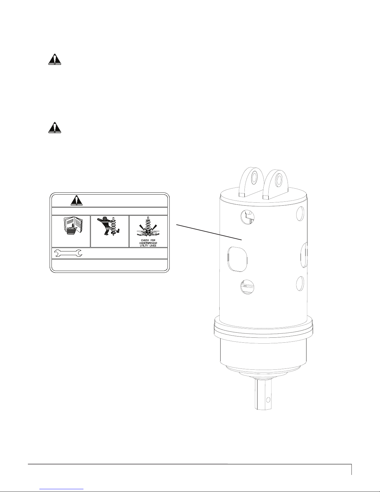
CAUTION: Alert yourself to the weight of the Auger
Drive. Do NOT exceed the recommended lift capacity
of the parent machine. Refer to you machines owners
manual.
SET-UP INSTRUCTIONS
OPERATING PROCEDURES
5. Once the required hole depth is reached, allow the auger
to turn a few seconds at this depth to clean the hole.
6. Stop rotation of the auger and raise the auger out of the
hole. Swing the auger away from the newly drilled hole.
Spin the lose material off the auger.
Note: Do not reverse the auger rotation while the auger is
still in the hole. The lose material will back ll the hole.
7. If necessary, repeat steps 4 through 6 to obtain a
cleaner hole.
OPERATIONS TO AVOID
1. In some soil conditions or when excessive down
pressure is applied, the auger may “screw” itself into the
ground. This can cause the auger to become stuck causing
the Auger Drive to stall. If this situation occurs, reverse the
auger rotation and slowly raise the auger from the hole.
2. If the auger becomes lodged under rocks, tree roots, or
other large obstructions, do not attempt to raise the auger
out of the ground. See Step 1 of this section to relieve
the auger.
3. Avoid excessive side loading. This can cause damage
to both the Auger Drive and the auger.
4. Keep all auger teeth and pilot bits in good condition.
Avoid using damaged teeth and holders.
• Following operation, or when unhooking, stop, set brakes,
disengage power drives, shut off engine, and remove the
ignition key.
• Store the unit in and away from human activity.
• Before long term storage, wash the unit with mild detergent
and water to remove any debris and grime.
• Do not permit children to play on or around the stored
unit.
• Protect the shafts and ports with a grease or rust-
inhibitor.
• Grease bearing seals.
• Check and tighten all bolts, nuts and screws. Repair any
part or cutting head components that are damaged.
• Paint all scratched or bare metal surfaces. Paint is
available from your Authorized Service Dealer.
• When storing the unit for any length of time be sure the
unit is stored with clean gear oil.

8 SA-70 (M135776.indd)
GENERAL MAINTENANCE
• Good maintenance is your responsibility. Poor maintenance is an invitation to trouble.
• Always use proper tools or equipment for job the at hand.
• Use extreme caution when making adjustments.
• Never use your hands to locate a hydraulic leak on attachments. Use a small piece of cardboard or wood. Hydraulic
uid escaping under pressure can penetrate the skin.
• Hydraulic uid escaping under pressure can penetrate skin and cause injury.
• Fluid accidentally injected into the skin must be surgically removed within a few hours by a doctor familiar
with this form of injury or gangrene may result.
• When disconnecting hydraulic lines, shut off hydraulic supply and relieve all hydraulic pressure.
• Clean hydraulic oil is essential! The majority of all hydraulic component failures are caused by contamination of the
hydraulic oil system.
• Always use dust caps and plugs on all quick disconnects when not in use.
• Check hydraulic oil daily for contamination. If contamination is present, determine the source and correct the
problem.
• When replacing bolts refer to this manual.
• Clean the exterior of the unit with a mild detergent and water to remove any debris and grime.
• Paint all scratched or bare metal surfaces.
• Check and tighten all bolts, nuts, and screws.
• Repair or replace any cutting head components that are damaged or worn.
• Check the gearbox for sufcient amount of oil.
• Check the Auger Drive output shaft for bends, cracks, breaks or wear. Replace if any of these conditions appear.
• Where replacement parts are necessary for periodic maintenance and servicing, genuine factory replacement parts must
be used to restore your unit to original specications. Manufacturer will not claim responsibility for use of unapproved
parts or accessories and other damages as a result of their use.
• If equipment has been altered in any way from its original design, manufacturer does not accept any liability for injury
or warranty.
The Planetary gearbox used on your Drive Head uses a gear oil to keep the internal gears lubricated. To check and or
replace the oil, follow the steps below.
CHECKING THE GEAR OIL:
1. Make sure theAuger Drive unit is in an upright position
when checking the oil.
2. Slowly loosen the Oil Fill-Drain plug located on the
under side of the gearbox. As you reach the end of the
treads on the plug, oil should start to ooze out.
3. If you see oil starting to ooze out of the port, quickly
retighten the plug. This is an indication that the oil level
is adequate, but in order to correctly measure the amount
of oil ,the gearbox should be drained and the correct
amount of oil replenished.
CHANGING THE GEAR OIL:
1. Position the Auger Drive unit in a position in which
the oil can ow freely from the gearbox once the plug is
removed.
2. Place a drain pan under the drain port that will hold at
least one gallon.
3. Remove the drain plug and allow the oil to completely
drain out.
4. Position the gearbox for lling by orientating the unit so
that the same port used for draining can now be used to
ll.
5. Fill the gearbox with oil, until full. See oil specications
below:
CHECKING AND CHANGING THE GEAR OIL
Lubrication Recommendations:
SAE 80W90 GL-5 Oil
Density / 15 deg C: 0.895 Viscosity Index: 97
Viscosity @ 40 deg C: 138 Flash Point COC: 200
Viscosity @ 100 deg C: 13.9 Pour Point (deg C): -30

(M135776.indd) SA-70 9
Below you will nd some general maintenance instructions. For further information contact your authorized service
dealer.
• Clean the exterior of the unit with a mild detergent and water to remove any debris and grime.
• Check and tighten all bolts, nuts, and screws.
• Repair or replace any cutting head components that are damaged or worn.
• Clean the exterior and surrounding area near the hydraulic motor.
• Paint all scratched or bare metal surfaces.
TROUBLESHOOTING
MAINTENANCE
In the event your Pengo Auger Drive unit malfunctions or does not appear to have enough speed or power, please refer to
the section below to identify the cause of the problem and possible remedy. If the problem persists, contact yourAuthorized
Service Dealer for assistance.
SLOW SPEED (RPM) OR INSUFFICIENT DIGGING POWER:
• Low oil ow. Check parent machine specications.
• Auger Drive is too large for machine. Contact your Authorized Service Dealer.
• Check auger and teeth for excessive wear. Replace worn auger components.
NO OUTPUT ROTATION:
• Quick release couplers not engaged. Check connection.
• Quick release coupler faulty. Replace faulty coupler.
• Hydraulic oil tank is low. Fill oil tank to maximum level.
• Planetary gear failure. Contact your Authorized Service Dealer.
• Machine oil pump failure. Refer to parent machine manual.
BAIL HOUSING LEAKING OIL:
• Hose(s) of Fitting(s) leaking. Tighten or replace.
• Motor O-ring failure. Replace damaged O-ring.
OUTPUT SHAFT LEAKING OIL:
• Oil seal failure. Contact your Authorized Service Dealer.
• Hydraulic motor failure. Contact your Authorized Service Dealer.
AUGER BIT WILL NOT ENGAGE OR DIG:
• Auger bit is worn or damaged. Replace cutting head or entire auger bit.
NO TORQUE:
• Oil pressure is too low. Contact your Authorized Service Dealer.
• Drive unit too small for parent machine. Contact your Authorized Service Dealer.
• Hydraulic system is overheating. See the “Oil Overheating” section below.
HYDRAULIC OIL OVERHEATING:
• Oil pressure is too low. Set relief valve to machine specications.
• Hydraulic line is restricted. Inspect and repair.
• Auger continually stalling. Limit down pressure used.
• Hydraulic oil tank is low. Fill oil tank to maximum level.
• Insufcient oil capacity. Check oil cooler.
• Parent machine is too small. Couple Auger Drive to larger machine.

10 SA-70 (M135776.indd)
SA-70 PARTS BREAKDOWN
Figure 3

(M135776.indd) SA-70 11
Please order replacement parts by PART NO. and DESCRIPTION.
SA-70 PARTS LIST

12 SA-70 (M135776.indd)
LIMITED WARRANTY
Pengo, warrants its products against faulty design, material, and workmanship for the periods listed below. The
warranty starts on the delivery date to the retail owner and is non-transferable.
WARRANTY PERIOD
Gearbox: 24 months or 500 operational hours, whichever occurs rst.
Hyd. Motor: 12 months or 250 operational hours, whichever occurs rst.
WARRANTY SERVICE
The original owner must notify the dealer who sold the product after the owner believes a warranty condition exists.
Products returned must be shipped prepaid. When a warranty claim exists, Pengo will free of charge, including return
freight, repair or replace the product with a new or rebuilt unit at the manufacturer’s option. If further warranty help is
needed, the owner may contact Pengo Customer Service at: (800) 599-0211
WARRANTY EXCLUSIONS
This warranty is void if eld repairs have been made to the motor, gearbox, and controls without written approval. The
complete unit must be available for inspection in it’s original but alleged failed condition. This warranty does not apply
to normal wear or to damage resulting from accident, abnormal use, abuse, or neglect.
Pengo will not be responsible for the downtime by the customer, mileage cost, or loss of productivity incurred by the
dealer or contractor as a result of any defect in materials or workmanship of its products.
PRODUCT IMPROVEMENTS
Product improvement and modications is an on going process at Pengo. Pengo reserves the right to make changes
or additions to any product or to the warranty without incurring any obligations to make such changes available for
previously sold products.
Pengo makes no other warranty. All other warranties, whether expressed or implied, such as warranties of
mechantablity or tness for a particular purpose, are hereby excluded and disclaimed to the extent that they exceed
the warranties expressly granted in this limited warranty. In no event shall Pengo be liable for consequential or
incidental damages.
WARRANTY POLICY
Pengo reserves the right to determine whether products claimed to be defective shall be inspected by our personnel
in the eld or returned to the factory. If judged by Pengo to be defective in material or workmanship, the product will
be replaced or a credit issued at the option of Pengo.
Upon notication of defect, Pengo’s Inside Sales Department will issue a Return Materials Authorization (RMA)
number. All returns for replacement or credit MUST be accompanied by a RMA number. Products returned without
an RMA number will be rejected and returned to the sender freight collect. All returns must be shipped “prepaid”.
Products shipped “collect” will be refused. Proof of purchase such as invoice number must accompany returns.
All RMA’s must be returned within 30 days of the request.
RETURNED GOODS POLICY

(M135776.indd) SA-70 13
TORQUE CHART FOR COMMON BOLT SIZES
The chart below lists the correct tightening torque for fasteners. When bolts are to be tightened or replaced, refer to this
chart to determine the grade of the bolt and the proper torque. Except when specic torque values are list in a particular
application.
tpi = Nominal thread diameter in inches per inch.
Nm = Newton Meters.
Ft-Lbs = Foot Pounds
mm x = Nominal thread diameter in millimeters x thread pitch.
Bolt Size (In) Grade 2 Grade 5 Grade 8 Bolt Size (mm) Class 5.8 Class 8.8 Class 10.9
tpi Nm Ft-Lbs Nm Ft-Lbs Nm Ft-Lbs mm x Nm Ft-Lbs Nm Ft-Lbs Nm Ft-Lbs
1/4”-20 7.4 5.6 11 8 16 12 M5 X 0.8 4 3 6 5 9 7
1/4”-28 8.5 6 13 10 18 14 M6 X 1 7 5 11 8 15 11
5/16”-18 15 11 24 17 33 25 M8 X 1.25 17 12 26 19 36 27
5/16”-24 17 13 26 19 37 27 M8 X 1 18 13 28 21 39 29
3/8”-16 27 20 42 31 59 44 M10 X 1.5 33 24 52 39 72 53
3/8”-24 31 22 47 35 67 49 M10 X 0.75 39 29 61 45 85 62
7/16”-14 43 32 67 49 95 70 M12 X 1.75 58 42 91 67 125 93
7/16”-20 49 36 75 55 105 78 M12 X 1.5 60 44 95 70 130 97
1/2”-13 66 49 105 76 145 105 M12 X 1 90 66 105 77 145 105
1/2”-20 75 55 115 85 165 120 M14 X 2 92 68 145 105 200 150
9/16”-12 95 70 150 110 210 155 M14 X 1.5 99 73 155 115 215 160
9/16”-18 105 79 165 120 235 170 M16 X 2 145 105 225 165 315 230
5/8”-11 130 97 205 150 285 210 M16 X 1.5 155 115 240 180 335 245
5/8”-18 150 110 230 170 325 240 M18 X 2.5 195 145 310 230 405 300
3/4”-10 235 170 360 265 510 375 M18 X 1.5 220 165 350 260 485 355
3/4”-16 260 190 405 295 570 420 M20 X 2.5 280 205 440 325 610 450
7/8”-9 225 165 585 430 820 605 M20 X 1.5 310 230 650 480 900 665
7/8”-14 250 185 640 475 905 670 M24 X 3 480 355 760 560 1050 780
1”-8 340 250 875 645 1230 910 M24 X 2 525 390 830 610 1150 845
1”-12 370 275 955 705 1350 995 M30 X 3.5 960 705 1510 1120 2100 1550
1-1/8”-7 480 355 1080 795 1750 1290 M30 X 2 1060 785 1680 1240 2320 1710
1-1/8”-12 540 395 1210 890 1960 1440 M36 X 3.5 1730 1270 2650 1950 3660 2700
1-1/4”-7 680 500 1520 1120 2460 1820 M36 X 2 1880 1380 2960 2190 4100 3220
1-1/4”-12 750 555 1680 1240 2730 2010
1-3/8”-6 890 655 1990 1470 3230 2380
1-3/8”-12 1010 745 2270 1670 3680 2710
1-1/2”-6 1180 870 2640 1950 4290 3160
1-1/2”-12 1330 980 2970 2190 4820 3560

14 SA-70 (M135776.indd)
NOTES

(M135776.indd) SA-70 15
NOTES

16 SA-70 (M135776.indd)
Utility Headquarters
Iowa
500 East Highway 10,
Laurens, IA 50554
United States of America
PH: 800-599-0211
FX: 712-845-2497
Minnesota
13369 60th St. S.W.
Cokato, MN 55321
PH: 888-286-0982
FX: 320-286-5583
California
1541 M Street
Newman, CA 95360
PH: 209-862-1504
FX: 209-862-1520
www.paladinbrands.com
Table of contents
Popular Boating Equipment manuals by other brands

Seastar Solutions
Seastar Solutions BayStar Plus installation instructions

Westland
Westland 2-Bow Aluminum Bimini manual

SmartGyro
SmartGyro SG20 Operation manual

Floe
Floe 510-17700-00 Assembly instructions

Interphase
Interphase DG-1 Operation manual

Seastar Solutions
Seastar Solutions Seastar Jackplate Installation instructions and owner's manual