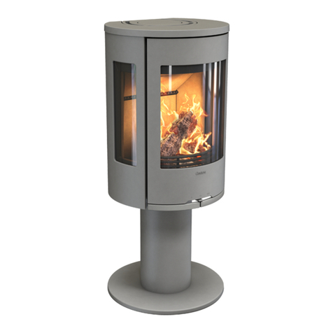
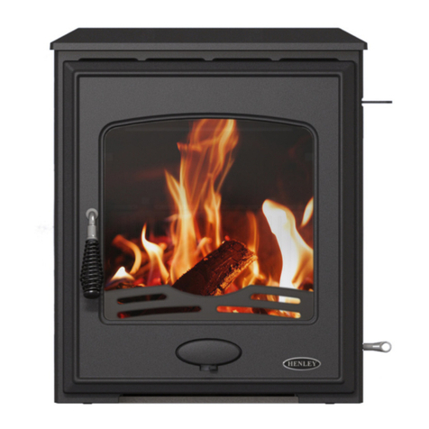
Penman Collection KASSEL User manual

INSTALLATION INSTRUCTIONS
KASSEL
WOOD BURNING STOVE
KAS - REV C - 10/19


CONTENTS
1.0 USER INSTRUCTIONS Page 4
1.1 Welcome
1.2 Fire Plus system
1.3 Product drawing
1.4 Cross section drawing
1.5 Health and safety
2.0 INSTALATION Page 7
2.1 Installation guide
2.2 Installation preparation
2.3 Ventilation
2.4 Distance to combustibles and heat sensitive materials
2.5 Connecting to the chimney
3.0 OPERATING INSTRUCTIONS Page 10
3.1 Suitable fuels
3.2 The Clean Air Act 1993 and smoke control areas
3.3 After use and maintainingthe perfect burn
3.4 Continued use and care
3.5 Cleaning
4.0 TROUBLESHOOTING Page 14
4.1 General troubleshooting
COMMISSIONING CHECK LIST Page 15

1.0 USER INSTRUCTIONS
1.1 Welcome
A very warm welcome from Percy Doughty, and thank you for purchasing the Olsberg Kassel wood burning stove from the Pen-
man Collecon. The stove is one of our nest and we hope you enjoy years of pleasure once your new stove is installed.
Percy Doughty prides itself in providing the very best products ensuring a meless design with longevity of service. Our stoves
will enhance your home and become a real focal point of beauty and elegance.
The stove has been designed in such a way as to perform to the opmum combuson which is both environmentally friendly
and ecient, with the best possible design in mind the heat produced will provide you with all the comfort and control need-
ed.
By reading these instrucons it will give you the best insight in to using your stove eciently and ulmately to prolong its life’s
service to your family. This instrucon manual will also help you when lighng your stove and through its general use and care.
Percy Doughty always recommends that the stove is installed by a HETAS registered engineer and serviced on an annual basis
but not limited to. The stove is a quality precision engineered product, if the installaon has been incorrect or the appliance
gets mistreated by overloading or using the incorrect fuel, it can damage the appliance and connecng ue system.
1.2 Fire Plus System
The Fire Plus System of your OLSBERG stove provides opmal, environmentally friendly burning and – combined with an eec-
ve heat exchange system – high eciency.
Aer loading and lighng the fuel, the rst phase of the combuson process starts by proceeding to burn the gases leaving the
fuel. This is the me of, ”high ames”. Aer the ames reduce, the rest of the coal burns up in the second phase of the com-
buson process. This process is characterized by strongly glowing embers with no or only smaller, temporary ames.
Opmal and environmental friendly burning with high eciency can only be achieved if we provide the necessary quanty of
air at the appropriate places in all phases of the combuson process. Both the longer me spent in the combuson chamber by
gases mixed with air and the hot combuson chamber have a posive eect on the combuson process.
This eecve burning can be achieved by the Fire Plus System. The primary air ow through the openings of the grate is com-
pleted by the secondary air ow through the glass front and terary air entering at dierent heights of the combuson cham-
ber. Wood, wooden briquees and brown coal briquees are fuels of “high ame”.
At this height and later above the glowing embers secondary and terary air get inside in such way that mixing of the air and
gases and the me that gases spend in the combuson chamber (depending on their structure) results in good burning. The
excellent quality lining (chamoe, vermiculite) of the combuson chamber provides high temperature, helping the process.
Aer, that gases are lead through one or more dead-plates in the upper part of the stove, namely through a heat exchange
system, that consist of a pipe system where heat is transmied again.
Gases nally leave the stove through the ue outlet and then enter the chimney at a temperature of 250 – 330 ºC through the
connecng pipe. The remaining energy content of the gases provides the necessary feed pressure in the chimney, “motor of
the stove”. This is the operang principle of OLSBERG stoves.
Overloading:
Fireplaces are structurally not suitable for non-stop use. Only a relavely small amount of fuel must be loaded in the combus-
on chamber at any one me. More informaon about quanes of fuels to be used is given in technical data.
PAGE 4

1.0 USER INSTRUCTIONS
1.3 Product drawing
1.4 Cross section drawing
1Primary air
2Secondary air
3”Cold” air of room
4 Warm air
5 Escaping gases
6 Hot gases
7 Grate
8 Chamoe or vermiculite lining
9/10 Terary air
11 Charcoal pan
PAGE 5

1.0 USER INSTRUCTIONS
1.5 Health and safety
The necessary feed pressure for chimney examinaon given on the technical data sheet is the necessary minimum value at the
ue outlet of the stove. This is necessary for safe operaon of the stove. Pracce shows that higher, somemes too high, feed
pressure exists in chimneys. Such high feed pressure (more than 20 Pa) can lead to uncontrollable combuson process that can
damage the appliance itself, the connecng ue pipe and the chimney system as a whole. Contact a registered HETAS engineer
or a competent person about nding a soluon in such cases, we recommend the use of a feed pressure regulator (ow control
valve in the ue or providing secondary air inside the chimney).
Olsberg stoves comply with DIN 18891 (building category 1) and DIN EN 13240 standards.
Olsberg stoves are freestanding stoves that cannot be equipped with an individual cover or be built in as a re chamber insert/
cassee. You must not make any modicaons inuencing the operaon of the stove.
Remove all packaging and supporng materials from the chamber and all accessories from the ash drawer and the wood case.
Make sure that the lining of the re chamber and all pieces of the dead plates are in the correct place and ed correctly. Do
not use the stove without these components. Take care as the packaging material can contain nails and other sharp pieces of
metal, which can cause injury to you and the stove. Take care that the nylon and other wrapping materials do not get in chil-
dren’s hands, as they can cause suocaon. Carefully collect the packaging materials menoned above, and take them to the
local waste disposal site.
The stove is painted in high temperature paint and high quality heat resistant lacquer that gains its nal stability when heang
up for the rst me. The smell at the rst heang up derives from the evaporaon of the protecon lacquer in the paint. So the
heated room must be carefully venlated from me to me (every 1-2 hours). The smell will stop aer a while of burning.
Do not put anything on the stove before the rst heang up and do not touch its surface to prevent damage of lacquering. Use
protecve gloves for your own protecon and for the sake of the intactness of the lacquering.
The doors of the stove should be kept slightly open during the rst heang up so the insulaon cord does not sck to the front
of the stove.
Cauon
Surfaces are hot. When you operate the appliance wear gloves and use the operang handles of the stove. The glass is hot.
Keep children away.
Never use spirits, petrol or any other ammable and explosive substance for lighng the re.
Don’t place combusble objects inside the radiaon area of the replace, within 100 cm from the door of the combuson
chamber.
PAGE 6

2.0 INSTALLATION
2.1 Installation guide
In the absence of pernent installaon informaon, the Brish standards and current building regulaons must be followed
to ensure compliance and safety.
This appliance must be installed by a HETAS registered engineer and the installaon must be in accordance with the Brish
standards and current building regulaons. Please see below for guidance but not limited to and the statutory requirements.
BS 8303
BS EN 15287 1
BS EN 15316
BS EN 1856 – 1 2009
BS EN 1856 – 2 2009
Approved Doc J
Health and Safety at Work Act
The Provision and Use of Work Equipment regulaons
Personal Protecve Equipment at Work regulaons
Construcon Design and Management regulaons
Control of Asbestos
Working at Height regulaons
Manual Handling regulaons
The stove may be installed in to a locaon where addional re protecon measures need to be taken into consideraon. A
risk assessment must be completed by the registered HETAS installaon engineer or the principal designer for purposes of the
current Construcon Design & Management Regulaons.
Please see the technical data below for clearances to combusble materials, this will allow for a comprehensive risk
assessment to be completed.
PAGE 7
Material Cast iron/steel
Venlaon requirements Surface In accordance with
Brish Standards
Surface door rope size 12mm
Output 5kW
Overall dimensions mm (HxWxD) 957 x 520 x 413
Weight 98kg
Draught pressure max 20pa
Draught pressure min 12pa
Terary air Yes
Combuson System Primary/secondary
Heang area 90m3
Flue outlet opons Top and rear
Flue collar size 125mm
Average temp at ue collar 348°c
Distance from boom of stove to
centre of rear ue outlet
839mm
Diameter of external ue spigot 100mm
Distance from boom of stove to
centre of direct air connecon
190mm
Log size 250mm
Fuel weight 1.3kg
Moisture content 16%-20%
Distance to combusbles (side) 300mm
Distance to combusbles (rear) 200mm
Distance to combusbles (front) 500mm
Safety distance to combusbles
materials (furniture)
100mm
Adequate distance le for mainte-
nance (rear and sides)
150mm

2.0 INSTALLATION
2.2 Installation preparation
Consideraon must be taken in relaon to the appliance locaon and safe ue route in the rst instance in accordance with
the appliance instrucons and technical data. The chimney must be suitable for operang the appliance safely and all selected
components must be compliant in accordance to the relevant Brish standards.
The appliance and ue system must be installed by a HETAS registered engineer and pernent commissioning documents and
evidenced system checks of the installaon in its enrety must be le with the end user.
Locaon
Choose a locaon for the appliance close to the chimney to prevent the use of a long horizontal connecng pipe. All horizontal
rear connecons must not be more than 150mm.
The locaon of appliance must be at and level. The oor must also have the necessary load bearing capacity. The weight of
the appliance can be found on the aached technical data. In case the load-bearing capacity of the oor is too low, usage of a
plate for beer load distribuon might help, but a structural engineer must advise if in any doubt.
Fixing Ceramic Glass or Soapstone Lid
Before connecng the stove, please take o all accessories that are not aached, such as top soapstone/ceramic le or the
soapstone /ceramic les placed in the warming plate. This way you can prevent these parts from falling while moving the
stove. Do not aempt to maneuver the stove in to posion or work on the ue with the soapstone or ceramic top in place as it
may become damaged. For further informaon to retrot any soap stone covers then the manufacturer must be contacted in
the rst instance.
2.3 Ventilation
Venlaon must be provided in accordance with Approved Document J .If the appliance is to be installed in to a room which is
completely airght, a separate external air inlet pipe is needed to guarantee a sucient supply of air for the safe operaon of
the appliance. The appliance may have an oponal connecon for the use of an external direct air supply and for guidance on
installaon, please see the Percy Doughty Technical Bullen #002.
2.4 Distance to combustibles or heat sensitive materials
The technical data Fig 2.1 shows the distances to combusble and heat sensive materials.
In case of combusble oors, being sensive to a rise in temperature, non-combusble oor protector must be used. This oor
protector must reach 500mm beyond the front (from the charcoal pan), 300mm beyond the side (from the inner wall of the
combuson chamber) of the appliance. The material of the oor protector can be made of metal or glass.
The given minimum safety distances from combusble or heat sensive materials must be adhered to at all mes and not
compromised, this will include all areas of the appliance front, rear & sides.
PAGE 8
The connecng ue pipe must be of single wall
construcon and must t inside the collar on the
appliance – the connecng ue pipe must be a
minimum vercal length of 600 mm directly above
the top ue outlet to create laminar ow of the
exhaust gases and reduce the deposion of soot
and tar.

2.0 INSTALLATION
2.5 Connecting to the chimney (including the connecting flue pipe)
Diameter of ue outlet is 125mm
The appliance is equipped with a top and rear outlet. We recommend the top outlet is used for best performance because of
combuson technological reasons. However the stove can also be connected from the rear (technical data contains the
connecon height), remove the ue outlet from the top of the appliance and the blanking plate from the back. Connect the
ue outlet collar on to the rear ensuring the top outlet is sealed using the blanking plate. Check all outlets for spillage when
operang the appliance. The heat plate must be used to protect the rear outlet if not in use.
Top connecon:
The minimum length of the connecng ue pipe must be 600mm and it must be inserted into the collar. It must not sleeve
over the collar and rest on the covers as referenced below
Soapstone Top
Ceramic/Glass Top
The connecng ue pipe must be in accordance with BS EN 15287‑1.Twin wall connecng ue pipe is not permied and appli-
ance adaptors are not recommended and must be approved by the manufacturer prior to use.
*Please refer to Percy Doughty Technical Bullen #001 for further guidence*
Connecng to the chimney:
Single-skin connecng ue pipes shall not be used as a complete chimney; they shall only be used to connect an appliance to a
suitable chimney or twin wall system chimney.We recommend the use of a connecng twin wall adaptor for connecng to the
chimney. The insert has to be fully installed into the chimney in order to prevent movement during normal use which could
cause joint separaon and leakage to occur between the appliance and the ue such as to impair the ability of the chimney to
evacuate products of combuson safely to the outside atmosphere. All connecons must be exact and insulated. All combus-
ble materials have to be removed within a 200mm radius of the insert and have to be replaced by heat resistant/non-
combusble material.
If there is wallpaper in the direct vicinity, it must be removed from behind the stove and from the side.
Fixing Ceramic Glass or Soap stone Lid
Before connecng the stove, please take o all accessories that are not aached, such as top soapstone/ceramic le or the
soapstone /ceramic les placed in the warming plate. This way you can prevent these parts from falling while moving the
stove. Do not aempt to maneuver the stove in to posion or work on the ue with the soapstone or ceramic top in place as it
may become damaged. For further informaon to retrot any soap stone covers then the manufacturer must be contacted in
the rst instance. Follow the direcons below when you light the re for the rst me.
PAGE 9

3.0 OPERATING INSTRUCTIONS
3.1 Suitable fuels
Please note that HETAS Ltd Appliance Approval only covers the use of wood logs and approved smokeless fuels on this
appliance. HETAS Ltd. Approval does not cover the use of other fuels either alone or mixed with the recommended fuels listed
above, nor does it cover instrucons for the use of other fuels.
Use the following fuels only:
Dry wooden log (beech, oak)
Wooden briquee
Brown coal briquee
You can nd the exact informaon on the technical data and on the appliance data badge. You must only burn the specied
fuel and failure to burn the correct fuel can damage the appliance and chimney system. This would also invalidate the warranty
of the appliance.
Depending on your choice of the fuels listed above, be sure that you use fuels of good quality.
Wooden logs reach 15-20% humidity which is the most appropriate for heang if they are stored outside for 1to 2 years (if they
are covered and protected from rain). Recently cut wood has a high moisture content and burns poorly and causes soot. Apart
from its very low heang value it is also a pollutant to the environment. High condensaon and tar can lead to blockage in the
stove and especially in the chimney. In all cases it causes deposit on the glass front and emissions that need to be avoided.
Burning wood is recommended for operang the appliance at its nominal capacity. You can get the exact data at a fuel
supplier. Load the replace with fuel according to heat demand. The heang value of 1 kg of dry wood is 4 – 4-5 kW/h. So you
can place about 1.3 kg of wood into a stove of 5 kW capacity every hour.
When burning wood, if you would like to reach a lower capacity, do not restrain the re. Put less wood in at one me instead.
Don’t throw the fuel in the combuson chamber, because it can damage or break the chamoe or vermiculite les. Be aware
that the volume of some types of wooden briquees increases during burning. Choose the wooden briquee that has the
appropriate size to the measurements of the combuson chamber and does not increase in size while burning.
You can use brown coal briquee for burning at nominal capacity just as wood or wooden briquee. Apart from that, it is also
excellent for keeping the embers glowing during the night (about 10 hours). In the case of brown coal briquees, wait unl the
fuel is completely burned through and close the primary air regulator to keep the embers burning only aer that. The types of
fuels that can be used, the maximum quanes that can be loaded at one me and the descripon of sengs for the air
regulators, can be found in the aached technical chart.
Reducing emissions
You can only avoid unwanted emissions by the use of the specied fuels. Put only the amount of fuel in the replace that is
appropriate for necessary heat transmission. Burning more fuel is unnecessary and leads to unwanted emissions. Don’t burn
waste in the appliance or products that can dramacally pollute the environment. This will also damage the appliance. The
use of other fuels than the ones listed above is not allowed.
You MUST NOT burn the following materials in the replace:
Wet or treated wood,
Wood-shavings, sawdust,
Inner bark, bark, shavings panel,
Coal dust,
Waste, scrap, plasc, rubble
Paper and cardboard (apart from lighng the re)
PAGE 10

3.0 OPERATING INSTRUCTIONS
3.2 The Clean Air Act 1993 and smoke control areas
Under the Clean Air Act local authories may declare the whole or part of the district of the authority to be a smoke control
area. It is an oence to emit smoke from a chimney of a building, from a furnace or from any xed boiler if located in a
designated smoke control area. It is also an oence to acquire an “unauthorised fuel” for use within a smoke control area
unless it is used in an “exempt” appliance (“exempted” from the controls which generally apply in the smoke control area).
In England appliances are exempted by publicaon on a list by the Secretary of State in accordance with changes
made to secons 20 and 21 of the Clean Air Act 1993 by secon 15 of the Deregulaon Act 2015. Similarly, in
Scotland appliances are exempted by publicaon on a list by Scosh Ministers under secon 50 of the Regulatory
Reform (Scotland) Act 2014. In Northern Ireland appliances are exempted by publicaon on a list by the
Department of Agriculture, Environment and Rural Aairs under Secon 16 of the Environmental Beer regulaon
Act (Northern Ireland) 2016. In Wales appliances are exempted by regulaons made by Welsh Ministers.
The Firefox 8 Eco and Classic 8 Eco have been recommended as suitable for use in smoke control areas when
burning dry wood and the “authorised” smoke free solid fuels.
The “authorised” solid fuels you are permied to burn in a smoke control zone include: anthracite (this is naturally
occurring smokeless fuel and is the test fuel normally used and recommended), Ecoal 50, Homere, Homere ovals,
Phurnacite, Taybrite and Mulheat.
3.3 After use and maintaining the perfect burn
Follow the direcons below when you light the stove for the rst me.
A high burning temperature is necessary for the fuel to catch re quickly so put enough
re-starter on the grate at the lower part of the combuson chamber. Put 2 or 3 smaller
pieces of wood or a similar quanty of wooden briquees, or 3 to 4 pieces of brown coal
briquees on the grate (see picture A)
Aer lighng the re, shut the door leaving it ajar. Only leave the door ajar when you light the
re for the rst me (aer the rst me you will shut the door completely) and fully open all
air regulators. Aer the wood or briquees have caught re you can adjust the amount of air
owing into the stove to suit your preference.
Aer a layer of glowing embers has been formed and you can no longer see any ames, you
can place more fuel into the stove and set the desired output with the aid of the air regulators
(see picture B, C1 and C2)
Always maintain opmal burning. If you use too much fuel or let too much air ow into the
combuson chamber, you may overload the appliance. Important note: this leads to high
temperature and emissions which should be avoided.
The appliance is painted with a high quality heat resistant lacquer that gains its nal stability
during the rst heang. The smell produced from the rst heang derives from the
evaporaon of the protecng lacquer in the paint and is completely normal. The room must
be venlated from me to me to allow the smell to disperse (every 1-2 hours).
Do not put anything on the stove before the rst use and do not touch its surfaces as it will
cause damage to the lacquering. Use protecve gloves for your own protecon and the
integrity of the lacquer.
The door of the stove should be kept slightly ajar during rst use to prevent the insulaon cord
from scking to the front of the appliance.
PAGE 11

3.0 OPERATING INSTRUCTIONS
3.4 Continued use and care
Always empty the ash drawer before each use, while the unit and the ashes are cold, because a full ash drawer can:
Obstruct air supply
Damage the grate
Always store the ash in a re-proof container. Do not put the container close to combusble materials or place it on a
combusble surface. Use a protecve plate if necessary. Pour the ash into a waste receptacle only aer you make sure that it
has completely cooled down. Aer emptying the ash drawer, replace it immediately.
Connue the lighng procedure according to the secon 3.3”Aer use and maintaining the perfect burn”.
Load more fuel only if the current fuel is only glowing and ames are not visible any more. When loading more fuel, open the
door of the combuson chamber slowly so that the smoke gases cannot ow out through the door. Level the glowing embers.
Put the amount of fuel necessary for the desired heang capacity on the embers, leaving an inch of space between each piece.
Close the door immediately aer loading the fuel and keep it closed during use.
Set the air regulators according to the nominal capacity, or in case of brown coal briquees as desired aer it has burned down
to embers. Repeat the procedure aer the fuel has burned down and always maintain opmal burning.
Never put more fuel in the stove at one me than is specied. (See technical data on page 6)
Only one poron of fuel can be burned at the same me. Load more fuel only aer the fuel in the unit already has
burned down.
Always check that there are not too many glowing embers piling up in the combuson chamber.
Do not restrain the re, load less fuel instead, and never close the primary air regulator completely.
Your stove is equipped with an automacally closing door. It can be operated only with a closed door.
Open the door only if you want to load more fuel and only if the previous amount has burned down to embers.
Remember that the appliance can become extremely hot when in operaon therefore it is important to ensure children
and vulnerable persons are aware of the risk at all mes .
Maintain the sengs of the air that is necessary for the burning capacity of the stove and keep in mind that the sengs of the
air depend considerably on the actual chimney draught. You can set the controls to achieve your own personal heat
preference. Not using the air sengs correctly can lead to blackening of the glass front or damage to the appliance and
chimney system.
The lining of the combuson chamber (chamoe or vermiculite) can turn black when you light the re. This blackening
disappears when the stove reaches its operang temperature.
The condion of proper operaon of the replace is the appropriate chimney draught (Flow pressure). This is considerably
dependent on the temperature of the outer environment. In case of a higher outer temperature (above 15ºC) ow pressure
can considerably fall and if the appliance is used in these condions then its performance may be impeded.
Important Note: The appliance chimney system can catch re through neglect , therefore regular maintenance is essenal and
periods will dier dependent on usage. In the event of a suspected chimney re, call the emergency services immediately and
close down all air regulators if praccal to do so without the risk of injury or harm. Do not pour water onto the re as this could
lead to an explosion, do not aempt to tackle the re, evacuate the property and wait for the emergency services to aend.
PAGE 12

3.0 OPERATING INSTRUCTIONS
3.5 Cleaning (to be performed only when stove is cold)
What Frequency Utensil
Combuson chamber of stove Min. once a year
but not limited to
Hand broom
Vacuum cleaner
Smoke outlet Min. once a year
but not limited to
Hand broom
Vacuum cleaner
Copper elements As necessary
Copper cleaning agent or other substance with Teon con-
tent (when it is cold)
Glass As necessary
With stove glass spray or glass cleaning agent (when it is
cold) Do not use anything abrasive that may scratch the
glass.
PAGE 13

4.0 TROUBLE SHOOTING
4.1 General troubleshooting
Weather condions may aect the performance of the appliance and temperatures above 15C may impede the ow pressure
of the appliance.
What can you do?
1. Open the primary air regulator a bit more, and fully open the secondary air regulator.
2. Use only a small amount of fuel at rst.
3. Use only a small amount of fuel when reloading.
4. Shake o the ash more oen.
5. Do not restrain the re.
6. Burn through the brown coal briquees very well and close the primary air regulator for keeping embers glowing only
aer that.
7. As a last resort, do not use the stove in a transion period.
What are the causes?
1. There is no proper draught at heang up, potenally caused by either:
A: Chimney or stove pipe is not closed properly.
B: Measurements (Height, ue conguraon) of the chimney are not appropriate
C: The door of the stove/supplementary air regulator or the door to another stove is connected to the same
chimney is open.
The room or space is not being adequately heated up by your appliance?
1. Is the appliance disproporonately small or incorrectly sized?
2. Is there too much ash in the combuson chamber?
3. Is the liner blocked due to the use of incorrect fuel being used?
4. Is the terminal blocked?
5. Is the air regulator closed?
The appliance is giving o too much heat?
1. Is the air regulator opened too far?
2. Is the chimney draught (Flow Pressure) too high?
3. Did you load too much fuel at once?
4. Is the fuel being used the correct?
The grate is damaged or corroded, bricks have cracked?
1. The replace has been overloaded.
2. You didn’t empty the ash drawer suciently during its connued use
3. Chimney draught (Flow pressure) is too high.
PAGE 14

COMMISSIONING CHECKLIST
Ensure the serial number has been recorded on the front
of this manual for any future use
Ensure the door seals are in good condition and that the glass
is secured correctly in the door (do not over tighten the glass
as this will prohibit its expansion and could cause the glass to crack)
Ensure that all internal components are fitted correctly (these may
have shifted in transit)
Ensure that the appliance operates correctly during the first firing
Ensure the customer is aware that fumes may be given off during
the first firings as the paint cures
Advise the customer on the safe operation of the appliance
Leave the instruction manuals, operating tool and glove for the
customer’s use.
Record the flue draught reading of the appliance
PAGE 15

Brought to you by
Imperial Point
Express Trading Estate
Stone Hill Road
Farnworth
Bolton
BL4 9TN
Tel: 01204 868 550 Fax: 01204 868 551 Email: sales@percydoughty.com
www.penmancollection.com
Table of contents
Other Penman Collection Wood Stove manuals
Popular Wood Stove manuals by other brands

Napoleon
Napoleon S20 quick start guide

Nordpeis
Nordpeis Origo Exclusive Installation and user manual

HearthStone
HearthStone FFP20131 Assembly instructions

Blaze King
Blaze King King KEJ-1101 Owner's installation & operating instruction book

IronStrike
IronStrike Striker SA160 Installation and operation manual

J. A. Roby
J. A. Roby OLYMPIEN owner's manual