PennBarry iPlume User manual

iPlume
Laboratory Exhaust System
INSTALLATION, OPERATION AND MAINTENANCE MANUAL
Please read and save these instructions. Read carefully before attempting to
assemble, install, operate or maintain the product described in this document.
Protect yourself and others by observing all safety information noted in this
document. Failure to comply with these instructions could result in personal
injury to others and/or property damage.
IMPORTANT! Read before proceeding!

2www.PennBarry.com
TABLE OF CONTENTS
GENERAL SAFETY INFORMATION 3-4
GENERAL INFORMATION 5
LIFTING INFORMATION 6-7
DUCT INSTALLATION FOR iPLUME 8
iPLUME SYSTEM ASSEMBLY 9-12
iPLUME DRAINAGE PIPE/TRAP DETAIL (BY OTHERS) 13
PRE-START-UP CHECKS 14-15
MAINTENANCE 16-17
DAMPER AND DAMPER ACTUATORS 18
CONTROLS AND SINGLE POINT WIRING PANEL 19
PIEZOMETER RING 20
JIB CRANE MOUNTING INSTRUCTIONS 21
iPLUME WITH MIXING BOX 22
EXPLODED VIEW OF FAN FOR iPLUME ASSEMBLY
& EXPLODED VIEW OF MIXING BOX 23

3
www.PennBarry.com
GENERAL SAFETY INFORMATION
Only qualied trained personnel should install or maintain equipment described in this document. Improper installation can result
in electric shock, possible injury due to high speed moving parts, or other potential hazards. Special circumstances such as high
winds or wet surfaces must be considered when installing the unit. Contact a PennBarry engineer if any questions or issues arise or
if any other information is needed before installing or maintaining the fan.
1. Follow all local, state and federal electrical and safety codes, as well as the National Electrical Code (NEC), and the National Fire
Protection Agency (NFPA), where applicable. Follow the Canadian Electrical Code (CEC) in Canada.
2. Make sure that the wheel spins freely without hitting or rubbing on any parts or objects.
3. The motor must be grounded; failure to ground a motor can result in a serious safety hazard.
4. The fan impeller should not be operated at RPM’s exceeding the rated RPM. If fan speed is higher than rated, the motor may
over amp, causing serious damage to the motor and other moving parts of the fan.
5. Power cord must be free of any kinks or pinches and must not come into contact with grease, oil or other liquids, ammable
or otherwise.
6. Verify that incoming power to the unit is of the correct voltage stated on the unit and/or motor nameplate.
7. Turn unit o before opening any access panels.
Receiving
PennBarry fans are carefully inspected and tested before leaving the factory. When the unit is received, inspect the packaging for
any signs of tampering. Inspect the unit for any damage that may have occurred during transit and check for loose, missing or
damaged parts. Mishandled units can void the warranty provisions. If units are damaged in transit, it is the responsibility of the
receiver to make all claims against the carrier. PennBarry is not responsible for damages incurred during shipment. Avoid severe
jarring and/or dropping. Handle units with care to prevent damage to components or nishes. If the unit is scratched due to
mishandling, the protective coating may be damaged. Incorrect lifting may damage the fan and void the warranty.
Unpacking
Upon reception, verify that all required parts and the correct quantity of each part have been received. If any items are missing,
report these to your local PennBarry representative. Due to variation in shipping carriers and availability, some items are shipped
separate from one another. Conrmation of shipment(s) must be limited to only items on the bill of lading.
Always disconnect power before working on or near a fan. Lock and tag the service switch or breaker to prevent
accidental power up.
DANGER
When servicing the fan, motor may be hot enough to cause pain or injury. Allow motor to cool before servicing.
CAUTION
Precaution should be taken in explosive atmospheres.
CAUTION

4www.PennBarry.com
GENERAL SAFETY INFORMATION
Storage
Store in a dry, protected area being sure fan shaft, bearings and impeller are protected against dust and corrosion. If it is necessary
to store outdoors or within a building under construction, special care must be taken to prevent moisture, corrosion, dirt or
dust accumulation. Coat the shaft with grease or rust preventative compound. Cover and seal bearings to prevent entrance of
contaminants. Impeller should be rotated at least once a month to circulate the grease in bearings. If stored outdoors over seven
(7) days, cover completely with a tarp or heavy waterproof paper. Electrical connections and leads must be protected from moisture.
Block impeller to prevent natural rotation. Do not allow material of any kind to be piled on top or inside of fan.
Inspection and Maintenance during Storage
Long-term storage is dened as storage for period exceeding one month from the date the equipment was received. Fans and
motors should be stored in a dry, low humidity area indoors. Equipment which is to be installed, but not operated for several
months, should rst be blocked to take the weight o of the vibration isolators (if provided) and then given the same protection,
periodic inspection and maintenance as a unit in storage. To prevent puddle corrosion of fan bearings that undergo long-term
storage, the following preventive maintenance must be performed
1 Fan bearings must be re-lubricated every month until the fans are put into service. A clear 1/16” bead of grease must appear
on each side of the bearings. Fan wheels are to be rotated manually while the bearings are re-lubricated. Refer to the specic
bearing lubrication instructions located on the fan housing for the type of lubricant to use.
2 Motor bearings should be lubricated as recommended by the motor manufacturer.
Removing from Storage
Fans should be hoisted with slings placed around the fan housing. When a single hoist is used, a “spreader” will keep the sling from
slipping on the housing. Fans must be protected and maintained from the time of storage to the time of assembly and installation.
Ensure that the fan is in working order before assembly and installation. Be sure that no damage has occurred between storage
and time of assembly.
1 Ensure that all fasteners, ttings, screws, etc. are tightened to recommended specications.
2 Make sure that no parts or objects are rubbing on the fan wheel as it is turned.
Notes:
This document is applicable for the following PennBarry models.
iPlume-122LV iPlume-165HV iPlume-245LV iPlume-330HV
iPlume-122MV iPlume-165XV iPlume-245MV iPlume-330XV
iPlume-122HV iPlume-182LV iPlume-245HV iPlume-365LV
iPlume-122XV iPlume-182MV iPlume-245XV iPlume-365MV
iPlume-135LV iPlume-182HV iPlume-270LV iPlume-365HV
iPlume-135MV iPlume-182XV iPlume-270MV iPlume-365XV
iPlume-135HV iPlume-200LV iPlume-270HV iPlume-402LV
iPlume-135XV iPlume-200MV iPlume-270XV iPlume-402MV
iPlume-150LV iPlume-200HV iPlume-300LV iPlume-402HV
iPlume-150MV iPlume-200XV iPlume-300MV iPlume-402XV
iPlume-150HV iPlume-222LV iPlume-300HV iPlume-445LV
iPlume-150XV iPlume-222MV iPlume-300XV iPlume-445MV
iPlume-165LV iPlume-222HV iPlume-330LV iPlume-445HV
iPlume-165MV iPlume-222XV iPlume-330MV iPlume-445XV

5
www.PennBarry.com
GENERAL INFORMATION
Unit identication tags
Each unit has a permanently axed nameplate with various identications including, but not limited to, the unit model and serial
numbers, motor ratings and voltages.
The gure below is an example of a PennBarry unit nameplate. It includes all of the specications of the unit, as referenced above.
When contacting your PennBarry representative, please have the information on the nameplate readily available, as this will help
to streamline your help request.
Fan components may arrive in pieces or assemblies depending on the fan conguration. Components of the fan will have matching
nameplates, and these components should not be mixed with other PennBarry fans. If mismatched components are installed in the
same fan, fan performance may be reduced.
Pre-Installation information
Ensure that the mounting surface where the unit is to be installed is completely level and free of debris. The mounting surface must
also be able to bear the entire weight of the fan. See roof curb installation instructions for additional details.
Electrical service switches
An electrical service switch must be installed either on the unit or in visual proximity to the unit, so that the unit can be easily turned
o for maintenance or trouble shooting. These must be locked out when the unit is being maintained or serviced.
Moving parts
Any moving parts on the unit must have covers or guards to protect any servicers or personnel. These guards are to be installed in
accordance with local codes. The fan wheel must be secured before performing any maintenance on the unit; damage to the wheel
is possible if this precaution is not taken.
Guards (Motor/Weather cover)
All parts of the unit, including guards and covers, must be installed before attempting to start the unit. Do not operate the unit with
any missing pieces, particularly any guards or covers; this includes any hardware including nuts and bolts, which hold these covers
in place.
Air pressure and suction
Fans moving at any speed create suction with varying degrees of strength. Special consideration needs to be taken when working
around these units. Do not leave any loose articles of clothing or materials in or around air intake or fan inlet.
Power Ventilator for Smoke Control Systems
(1000* F for 15 min/500* F for 4 hrs)
For installation in accordance with NFPA-204M.
Ventllateur de Puissance pour un systeme de controle de
fumme (537.78* C pour 15 minutes/280* C pur 4 hour)
L’Istallation doit stre conforme au bulletin NFPA-204M.
See Motor Nameplate for Electrical Rating and Motor Protection
Se referer a la plaque singaletique du moteur concermant la classification
electique ainsi que la protection requises pour ce moteur
TM
Tag# Model Serial Fan RPM
Fan RPM
HP
Puissance en Chevaux
Voltage/Phase/Cycle Motor RPM SO#
MO#
Moteur RPM
Voltage/Phase/Frequence
NumeralModeleNumero D’etiquette

6www.PennBarry.com
LIFTING INFORMATION
The following is a list of recommendations for lifting the various assemblies of your iPlume fan system:
Discharge nozzle and stack extension may be pre-assembled and lifted as one assembly, or each component can be lifted separately.
These lifting methods are recommended.
Fans should be hoisted with slings placed around the fan housing. When a single hoist is used, a “spreader” will keep the sling from
slipping on the housing. If it is necessary to use hooks placed in lifting holes of fan, BE CAREFUL NOT TO DISTORT OR BEND THE
HOUSING. Large units may have lifting lugs or holes which should be used only to stabilize the unit while using a sling to support
the weight. Chain or wire slings should be well-padded where they contact the fan, especially where special coatings and paints are
involved. Rubber, phenolic enamels, etc. require special care as they may easily be damaged by contact in lifting. Even a small chip
will destroy the corrosion prevention seal of the coating and allow corrosion to start. Always repair scratched surfaces with touch
up of like coating prior to installation. The unit discharge nozzle is to be lifted per handling recommendations provided above by
specied mounting points at the top of the cone, separately from the other sections of the unit.
A. Lifting windband and nozzle: Use a sling in conjunction with lifting lugs at top of nozzle.
B. Lifting fan section: Use a sling in conjunction with lifting lugs at top of fan.
C. Lifting plenum section: Use a sling in conjunction with lifting lugs located at corner gussets
of isolation damper box.

7
www.PennBarry.com
LIFTING INFORMATION
Size Nozzle &
Windband (lbs)
Belt Drive Fan
Section w/o
Motor (lbs)
Direct Drive Fan
Section w/o
Motor (lbs)
1x1 Mixing Box (lbs) 2x1 Mixing Box (lbs) 3x1 Mixing Box (lbs)
122 98 258 209 718 1436 2154
135 118 295 239 773 1546 2319
150 144 375 289 869 1738 2607
165 151 416 329 907 1814 2721
182 186 501 414 1441 2882 4323
200 220 571 481 1514 3028 4542
222 269 705 599 1640 3280 4920
245 254 818 709 1666 3332 4998
270 298 995 859 1644 3288 4932
300 366 1213 1060 1892 3784 5676
330 439 1429 1268 2063 4126 6189
365 390 1968 1773 2243 4486 6729
402 472 2294 2100 2373 4746 7119
445 574 2792 2559 2965 5930 8895
Size Fan Curb (lbs) 1x1 Plenum Curb (lbs) 2x1 Plenum Curb (lbs) 3x1 Plenum Curb (lbs)
12" 18" 24" 12" 18" 24" 12" 18" 24" 12" 18" 24"
122 228 263 356 342 395 541 571 659 895 735 851 1176
135 244 281 381 365 421 577 609 701 952 775 903 1248
150 259 298 405 459 436 736 758 881 1198 965 1135 1569
165 275 315 429 467 544 748 770 895 1217 981 1152 1593
182 298 341 465 521 605 833 861 995 1353 1094 1277 1765
200 345 399 544 576 671 924 951 1104 1502 1210 1420 1965
222 368 425 581 607 706 972 1003 1161 1580 1274 1491 2073
245 392 451 617 615 714 984 1015 1174 1598 1288 1507 2085
270 415 477 653 639 741 1021 1054 1217 1657 1337 1560 2170
300 486 560 768 709 824 1137 1170 1354 1846 1485 1739 2409
330 517 595 817 764 885 1221 1260 1454 1981 1597 1863 2580
365 556 638 877 787 911 1258 1298 1496 2038 1642 1914 2623
402 626 722 993 849 986 1361 1400 1618 2207 1774 2074 2878
445 673 774 1065 896 1038 1434 1477 1703 2322 1868 2179 3023
Windband and nozzle assembly can be lifted as one piece, the fan sections and plenums must be lifted separately.
CAUTION

8www.PennBarry.com
DUCT INSTALLATION FOR iPLUME
Notes:
Steel, concrete or wood roof support is per structural engineer and in accordance with load requirements and applicable building codes.
Bottom Inlet Duct Connection
If a customer supplied duct is to be installed on the unit, it is to be secured between the curb cap of the unit and the curb’s top
edge. If there is an isolation damper to be installed, it is to be installed between the duct and the unit.
Option 2
• No isolation damper in duct
• Side inlet on iplume with Bypass Air Plenum
Option 1
• No isolation damper in roof curb
• Bottom inlet on iplume
iPlume with curb
cap or iplume with
Bypass Air Plenum
Roof curb
Duct
Duct and
expansion joint
by others
Weatherhood
Bypass Air
Plenum Duct to bypass Air Plenum
iPlume

9
www.PennBarry.com
iPLUME SYSTEM ASSEMBLY

10 www.PennBarry.com
iPLUME SYSTEM ASSEMBLY
Sequence for Curb Installation to Roof
The roof curb is to be placed and fully secured to a level steel or concrete roof structure (by others) with 3/8-16UNC Gr. 5 cap
screws and washers (supplied by others) as depicted below. Fasteners must be centered on the curb ange and bolt spacing is
not to exceed 6”. It is important that a Structural Engineer is consulted to verify the support structure and attachment method can
adequately support the fan weight and wind loads.
In order to avoid structural resonance, the structure must be designed with adequate stiness so the natural frequencies are at
least 120% above fan maximum operating speed.
Notes:
An inadequately designed roof structure may impact fan performance, longevity, and/or result in injury. All roof structures should be in
accordance with all local building codes.
11
www.PennBarry.com
iPLUME SYSTEM ASSEMBLY
Sequence for Bypass Plenum or Fan to Roof Curb
Install the provided roof curb gasket by adhering it to the top of the roof curb. Rig and lift plenum or fan (if plenum not provided)
as per lifting information section of this manual and place carefully on top of roof curb ensuring not to damage gasket material.
Dill 0.348 pilot holes into roof curb using plenum or fan as a template and install provided 3/8 self-threading fasteners. Figures
below represent the typical installation of plenum and fan to curb.
For fans without a plenum, the fan is to be installed in a similar manner by using the fan slots as fastener pilot holes.
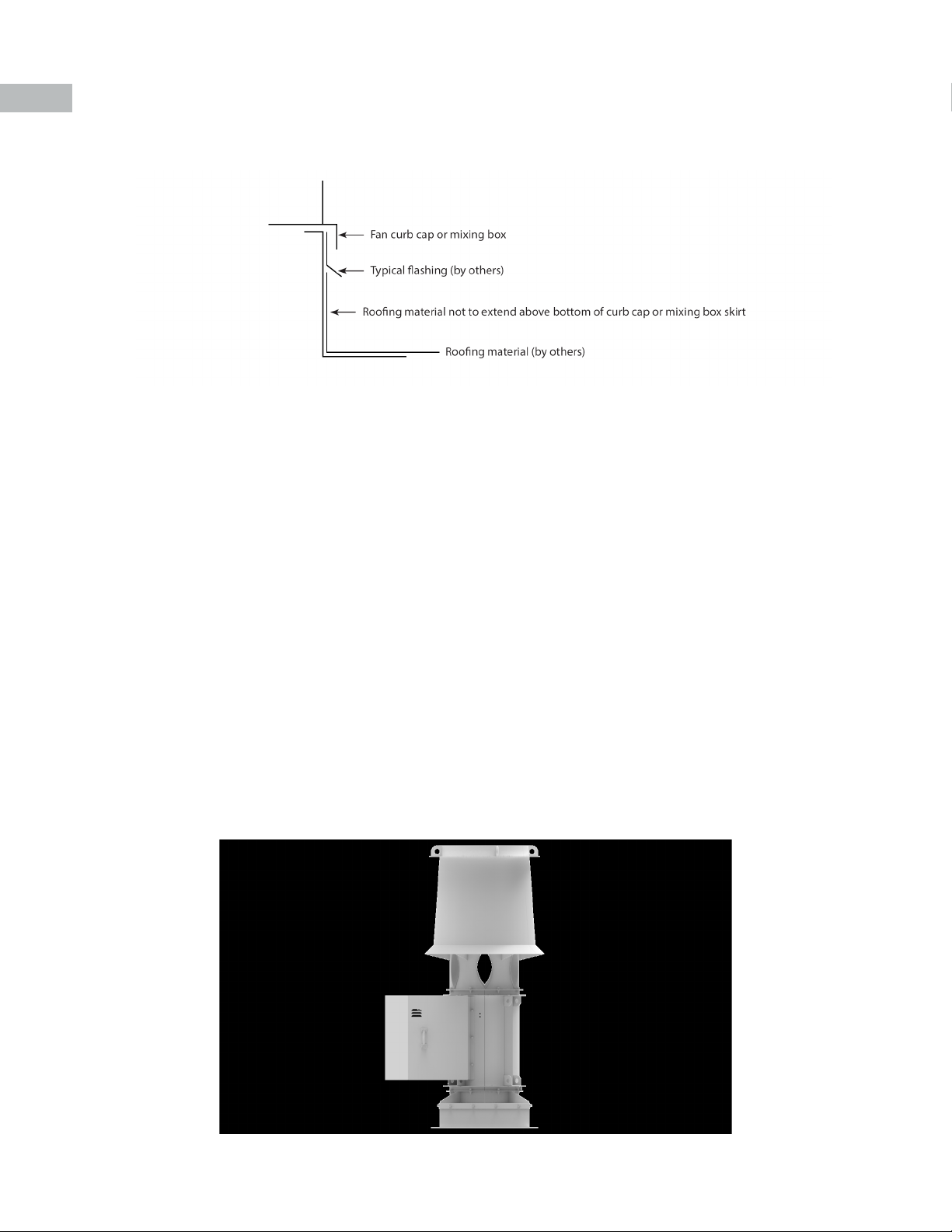
Flashing Detail
Typical installation of plenum onto roof curb
Typical installation of fan without plenum to roof curb.

12 www.PennBarry.com
iPLUME SYSTEM ASSEMBLY
Sequence for Fan to Bypass Plenum
Install gasket onto the top of the plenum, using the adhesive to adhere the gasket to the plenum.
Place the bottom of the fan onto the top of the plenum and secure with mounting hardware through the units mounting holes as
shown in diagrams.
Sequence for Discharge Nozzle to Fan
Install gasket onto the top of the fan section, using the adhesive to adhere the gasket to the fan.
Install discharge nozzle to the top of the fan section as shown in the diagrams, and secure with mounting hardware through the
units mounting holes; be sure to include gasket.
13
www.PennBarry.com
iPLUME
DRAINAGE PIPE/TRAP DETAIL (BY OTHERS)
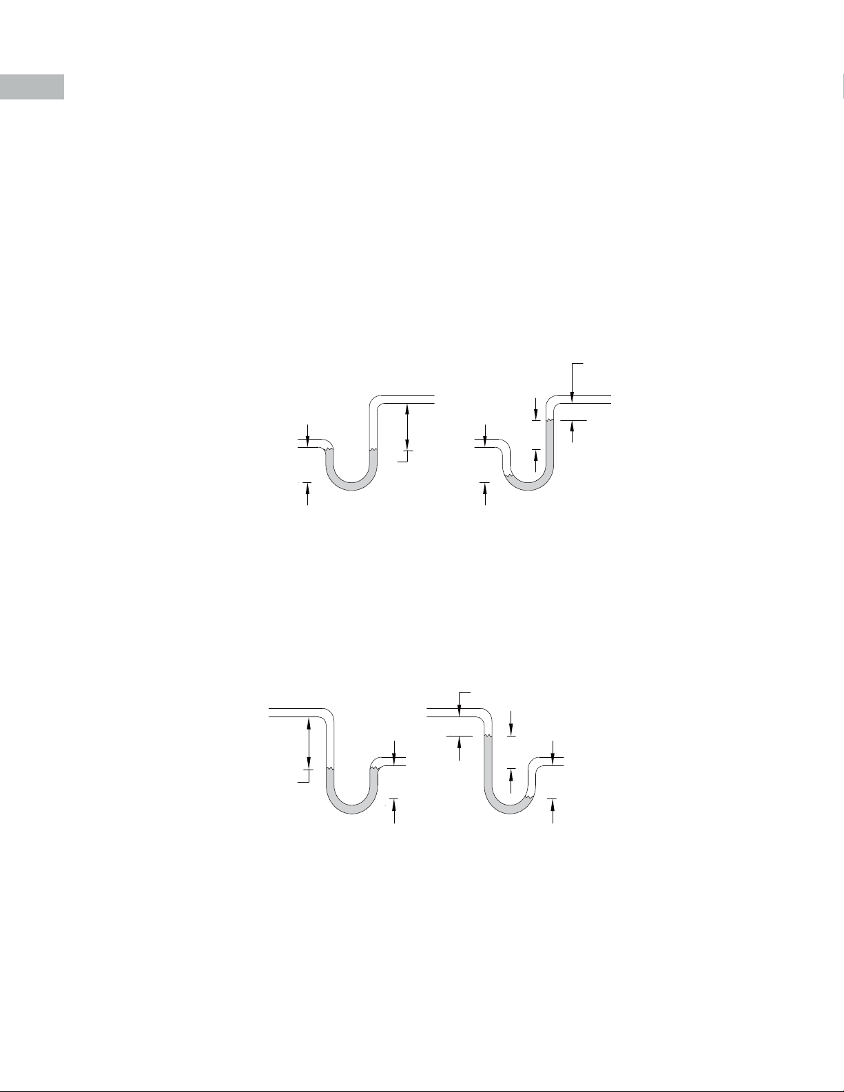
Drainage ports are provided on both the fan housing and plenum box to provide drainage for the system. It is recommended that
these drains are piped to allow proper drainage of any condensation collected in the unit.
1. Drain connections are 3/4 inch NPT
2. Drain piping installed must have proper slope
3. P traps are to be lled to proper level prior to unit start up
Positive Pressure Trap on Tubular Fan Housing
Negative Pressure Trap on Bypass Air Plenum
N = Negative fan pressure (inches W.C.)
H = N - (0.5 inches minimum
H/2 H/2
H
1.25 inch minimum
N
FAN ON
FAN OFF
N = Negative fan pressure (inches W.C.)
H = N - (0.5 inches minimum)
H/2 H/2
H
1.25 inch
minimum
N
FAN ONFAN OFF
Connect
this end
to fan drain.
Rain Mitigation
Inline laboratory exhaust fans, such the iPlume, require mitigation of water below the fan if the fan is not running at all times. The
iPlume has drains in the nozzle and funnel but water entry is possible during heavy rain events. In bottom intake installations rain
mitigation must take place in the ductwork below the fan. A side intake mixing box is another solution, the side intake mixing box
will not allow water into the ductwork.
Fan should be selected at nozzle velocities of 3000 fpm or higher to prevent rain from entering during operation.

14 www.PennBarry.com
Ensure that all mounting hardware and fasteners are properly installed and tightened to recommended torque specications.
Ensure that the wheel is aligned and has the correct spacing in relation to the inlet venturi; it should be centered in the inlet venturi
as well. If adjustment is needed, loosen the inlet venturi bolts and shift the inlet venturi until the radial gap is the same at every point
across the circumference of the inlet venturi.
If adjustment of the overlap between the wheel and inlet venturi is needed, loosen the taper lock bushing, slide the wheel forwards
or backwards until the correct overlap is achieved, and then tighten the set screws back down.
There is a rotation sticker on the unit that species the direction the wheel should turn. Ensure that the wheel is rotating in the proper
direction before powering on the unit. In 3 phase units, simply switch two incoming leads to reverse rotation.
PRE-START-UP CHECKS
Airow
A
Notes: Any increase in fan speed represents a substantial increase in horsepower required from the motor. Always check motor load amperage
and compare to nameplate rating when changing fan speed.
Gap/ overlap dimensions
Size Inlet Venturi to Wheel Overlap Dimensions A (inches)
122
0.39
135
0.43
150
0.46
165
0.47
182
0.51
200
0.57
222
0.66
245
0.76
270
0.83
300
0.92
330
1.02
365
1.12
402
1.27
445
1.33

15
www.PennBarry.com
When the unit is removed from storage, all grease should be purged and replenished with fresh grease. The following check list should
be followed to ensure proper operation:
Operation Check List
Check fan mechanism components
• System connections are properly made and tightened.
• Impeller and fan surfaces are clean and free of debris.
• Impeller has been rotated by hand to verify it has not shifted in transit.
Check fan electrical components
• Motor is wired for proper supply voltage.
• Motor was properly sized for power.
• Motor is properly grounded.
• All leads are properly insulated.
PRE-START-UP CHECKS
Trial “bump”
• Turn on power just long enough to start assembly rotating.
• Check rotation for agreement with rotation arrow.
Perform checklist again until unit is operating properly. Verify
fastener tightness. These may have loosened during shipment or
installation.
• Bolts on inlet funnel.
• Motor bolt torque
• Nuts holding housing frame to base and base to
• Ground (customer specications)
• Bushing fastener torque
Ensure piezo tubing will not contact the impeller
A
B
C
A Hub
B Bushing
C Bushing screws
D Bushing set screw
C Bushing fastener torque
Bushing type Screw size Recommended toque
P2 5/16 - 18 192 in-lbs
Q2 3/8 -16 348 in-lbs
R2 3/8 -16 348 in-lbs.
S2 1/2 -13 840 in-lbs

16 www.PennBarry.com
MAINTENANCE
The benets of regular inspections and routine maintenance are well documented; regular service intervals keep the system
operating at peak eciencies, extend operational life and ensure safe product operation.
Notes:
In this section, routine service internals are recommended.
Scheduled maintenance must be performed on the unit after it is in operation to ensure that it runs eciently and reliably
BELTS
Improper belt tensioning is the most common cause of early
belt failures. As such, it is imperative to tension a belt down to
the correct tension, which is the lowest tension at which the belt
does not slip at peak running speed.
As a general rule, the belt should not deect any more than 1/64
inch for every inch of belt span.
It is advised to check the belt tension at least twice within 24
hours of installation and regularly with scheduled maintenance
thereafter. Adjust belt tension by loosening the bolts on the
motor plate to relieve the tension. Tighten belt tension by
tightening down the bolts on the motor plate.
Drive pulleys must be properly aligned, or belt slippage can
occur. If pulleys are not aligned, the unit will not run eciently,
and noise or premature failure can occur.
FASTENERS AND SET SCREWS
All hardware, screws and fasteners should be checked for torque at every scheduled maintenance
MOTORS
Most fractional horsepower motors provided with the unit do not require greasing or lubrication after they are installed. If motors
have grease ttings, then they should be re-lubricated according to motor manufacturer specications.
MOTOR FUSES
Fuses to be of the time delayed type.
REMOVAL OF DUST AND DIRT
The impeller and interior surfaces of the unit should be inspected and cleaned, if necessary, on a regular basis in accordance with
the maintenance schedule. Dirt and dust accumulation can throw the wheel o balance and cause other early failures in the unit.
Do not get water in bearings or motors when attempting to clean the unit.
FAN SHAFT BEARINGS
Bearings selected for Pennbarry fans are specially paired with the unit to achieve the maximum attainable eciency and performance
of the fan. As such, they are one of the most crucial parts of the fan and must be maintained and mounted accordingly.
BELT
ALIGNMENT
Ensure that all incoming power to the unit is switched o before attempting to service the unit. If this measure is not taken, serious
injury can occur to the servicer
CAUTION

17
www.PennBarry.com
MAINTENANCE
Ensure bearing set screws and collars are torqued to the correct specications upon installation and every scheduled maintenance
thereafter. Never mix lubricants or greases while re-greasing bearings; check bearing specications for the correct grease
recommended by the manufacturer.
• Lubrication intervals depend on many factors such as temperature, moisture, or dirt. Consult a local PennBarry representative
for lubrication recommendations.
• Lubricant should be selected based on the bearing manufacturer specications.
• If the unit is stored for longer than 3 months at a time, rotation of the shaft is recommended to free up grease in the bearing
* Lubrication interval is based on 12 hour per day operation and maximum 160°F. housing temperature. For 24 hour per day
operation, the interval should be cut in half.
** Lubricant should be added with the shaft rotating and until clean grease is seen purging from the bearing. The lubrication interval
may be modied based on the condition of the purged grease. If bearing is not visible to observe purged grease, lubricate with
number of shots indicated for bore size.
Shaft Size
OPERATING SPEED (RPM)
500 1000 1500 2000 2500 3000 3500 4000 4500 5000
LUBRICATION FREQUENCY (Months)
0.50” - 1.00” 6666664422
1.06” - 1.44” 6 6 6 6 6 6 4 4 2 1
1.50” - 1.75” 6 6 6 4 4 2 2 2 1 1
1.88” - 2.19” 6 6 4 4 2 2 1 1 1 -
2.25” - 2.44” 6 4 4 2 2 1 1 1 - -
2.50” - 3.00” 6 4 4 2 1 1 1 - - -
3.06” - 3.50” 6 4 2 1 1 1 - - - -
3.56” - 4.00” 6 4 2 1 1 - - - - -

18 www.PennBarry.com
DAMPER AND DAMPER ACTUATORS
Notes: Disconnect power to damper before attempting any maintenance.
Fan Size Bypass Damper Size ID (in) Max Flow per Damper (CFM)
122 14 4900
135 16 6200
150 18 7900
165 18 8700
182 20 10600
200 22 12800
222 24 16000
245 24 16000
270 24 16000
300 30 25000
330 30 25000
365 36 36000
402 36 36000
445 48 55000
If access is required to a gravity isolation damper, remove the panel adjacent to the weatherhood on the bypass air plenum section
and slide the damper straight out toward you.
When performing maintenance on a motorized isolation damper, unbolt the panel with the isolation actuator. Then, pull the panel,
actuator and damper assembly out.
Damper actuators, when supplied by PennBarry, are designed to be maintenance free. No lubrication is required.
Isolation damper
Bypass damper
Weatherhood
Pull Isolation
Damper in
this direction

19
www.PennBarry.com
CONTROLS AND SINGLE POINT WIRING
PANEL
Reference the iQ-LFC-Lab Fan Controller installation manual for details on PennBarry lab fan control system installation.
The optional single point wiring panel allows all of the dampers to be wired to one location for easy eld wiring.
Single Point
Wiring Box

20 www.PennBarry.com
PIEZOMETER RING
Dierence in the cone surface pressure and fan inlet pressure (∆p) can be correlated to the volumetric air ow rate (Q) using
equation shown below to an accuracy of 5%.
Q = K * √(∆p)
Q = Volumetric ow rate (CFM)
∆p= Dierential Pressure (inWC)
K = Fan constant, as noted in table below:
Fan Size K
122 2512
135 3336
150 4286
165 5236
182 6313
200 7453
222 8847
245 10304
270 11887
300 13787
330 15688
365 17905
402 20248
445 22972
HIGH-PRESSURE
SIDE
LOW-PRESSURE
SIDE
TUBE
TO DIFFERENTIAL
PRESSURE TRANSUDER
HIGH-PRESSURE
SIDE HOLE
ON INLET CONE
LOW-PRESSURE
SIDE HOLE
ON INLET CONE
Table of contents
Popular Laboratory Equipment manuals by other brands

Macherey-Nagel
Macherey-Nagel NANOCOLOR VIS II quick start guide

Metrohm
Metrohm 917 Coulometer manual

artisan
artisan Germinator 500 operating manual

VERDER
VERDER Carbolite Gero HTMA 4/220 Installation, operation and maintenance instructions

Globe Scientific
Globe Scientific GCM-24 user manual

Data Translation
Data Translation DT2802 user manual


