HIRAYAMA HVA-85 User manual
HIRAYAMA AUTOCLAVE
HICLAVE
HVA-85
HVA-110
OPERATION MANUAL
WARNING:
Be sure to read this operation manual carefully and handle it properly.
Issued on October 20, 2005. Revised on June 1, 2009
No. S04G-001-C
!

1
Introduction Refer to Page 6 for Contents
●This manual covers the operation and basic maintenance procedure for the Autoclave
HVA-85/110. Proper handling will allow the autoclave to demonstrate its full performance
and ensure a long lifetime for the instrument.
●Please confirm that this product conforms to your order, and confirm that it was not
damaged during transport. In the event of damaged or broken equipment, please contact
our authorized distributor in your region.
①No part of this document may be reproduced without permission.
②The contents of this document are subject to change without notice.
③This document has been carefully compiled. If you have any questions or necessary
information uncovered in the document, please contact our authorized distributor in your
region.
2
Read Carefully Before Using
●Determine the handling person responsible of this product.
●In this manual the following headings are applied to items to which great attention should be given:
WARNING : Precaution indicating an imminent dangerous situation which if
not avoided may lead to death or serious injury.
CAUTION: Precaution indicating a dangerous situation which if not
avoided may lead to moderate or slight injury.
IMPORTANT: Indicates items you are strongly advised to obey.
NOTE: Items that will aid in proper operation of the equipment.
WARNING:
●Never use the autoclave to sterilize any of the following hazardous materials or substances with
alkali content. Sterilization of such objects can cause explosion, corrosion of the working chamber
or chamber piping, and deterioration of gaskets.
List of Hazardous Materials
①Explosive substances
・Nitroglycol, nitroglycerin, nitrocellulose, and other explosive nitric esters.
・Trinitrobenzene, trinitrotoluene, picric acid, and other explosive nitro compounds.
・Peracetic acid, methyl ethyl ketone peroxide, benzoyl peroxide, and other organic peroxides.
②Ignitable substances
・Metallic lithium, potassium, sodium, yellow phosphorous, phosphorus sulfide, and red phosphorus.
・Celluloids, calcium carbide (carbide), lime phosphide, and magnesium powder
・Aluminum powder, magnesium powder, and metallic powders other than aluminum powder
・Sodium dithionite (or sodium hydrosulfite)
③Oxidizing agents
・Potassium chlorate, sodium chlorate, ammonium chlorate, and other chlorates
・Potassium perchlorate, sodium perchlorate, ammonium perchlorate, and other perchlorates.
・Potassium peroxide, sodium peroxide, barium peroxide, and other inorganic peroxides
・Potassium nitrate, sodium nitrate, ammonium nitrate, and other nitrates
・Sodium chlorite and other chlorites ・Calcium hypochlorite and other hypochlorites
④Flammable substances
・Ethyl ether, gasoline, acetaldehyde, propylene oxide, carbon disulfide, and other substances
whose flash points range from -30 to 0C.
・Methanol, ethanol, xylene, benzyl acetate (or amyl acetate), and other substances whose flash
points range from 0 to 30C.
・Kerosene, gas oil, turpenine oil, isopentyl alcohol (or isoamyl alcohol), acetic acid, and other
substances whose flash points range from 30 to 65C.
⑤Flammable gas (hydrogen, acetylene, ethylene, methane, ethane, propane, butane, and other
substances that are gases at a temperature of 15C under 1 atmospheric pressure.)
●When liquid with salt water and much salinity of salt agar etc. spills in the chamber, blowing,
discharge water in the chamber and wipe up
drop of water around the lid gasket beautifully.
It causes the corrosion of the chamber and the piping when leaving just as it is
●Check that the pressure is below "0Mpa" before opening the lid.
●Absolutely do not attempt to remodel or alter this product.
●Do not use this product near explosive gas, as a few parts used are not explosion proof structure.
!
!
!
!
0.2
0.3
0.4
0
0.1
0

3
CAUTION:
Foreign matter (metals, liquid) may enter through the vent hole. Operating the equipment with
such foreign matter inside may cause trouble with the equipment, fire or electric shock.
Do not forcibly bend, twist, tie or extend the power cord. Do not place heavy objects on the
cord. A damaged cord or exposed wire can cause fire or electric shock.
Never connect the power cord to a power supply other than one of the rated voltage.
Connection to such a power supply can cause fire or electric shock.
If grounded socket is unavailable, ground the equipment using a separate ground wire
before connecting the power cord to the power source.
Never ground to a gas pipe or vinyl chloride water service pipe.
Raise the lid slowly. When an impact is added to the lid, there is fear which the hinge of
the lid damages.
Close the lid after confirming that no foreign matter is adhering to the section contacting the
lid gasket. Foreign matter in this section can cause vapor leaks.
When using a waste processing bag or other kind of bag and disinfecting, place the bag in
the metal mesh holder and then insert it into the chamber. Using the bag “as is” can cause
excessive temperatures, pressures, lack-of-water, etc.
Be careful not to pinch your hands when closing the lid.
Do not put your face or hands close to the chamber when lifting the lid after operations are
complete; steam will gush out of the chamber.
The lid, chamber, gasket and panel are extremely hot immediately after the completion of
operation. Do not touch the equipment or you may get burned.
Put on heat insulating gloves before removing a substance from the chamber. Do not put
hands into the chamber until the steam has been vented.
Some time is required for liquids to cool. Be sure to check that the temperature has
dropped sufficiently before unloading a liquid from the working chamber or burns can result.
Do not unload the exhaust bottle or drain the chamber when the chamber is under pressure.
Boiling water or steam may gush out causing burns.
Do not remove the exhaust bottle before water in the bottle has sufficiently cooled.
If any abnormality occurs (e.g. abnormal sounds, smells, smoke), immediately shut the
power off. After checking to see that the abnormal condition does not continue, call our
authorized distributor in your region.
●If the display reading changes between the steps, turn the POWER switch off then on again.
If the problem continues, turn the power switch off and call our authorized distributor in your
region.
!

4
How to Read this Manual
●This operation manual consists of the following sections covering the information required for
proper operation of the Autoclave HVA-85/110:
Chapter 1. What is the Autoclave HVA-85/110?
This section describes the uses and features of the product, and the names and functions of its
parts.
Chapter 2. Installation
This section explains where the equipment should be installed and how to install it. The product
incorporates precision parts, so be sure to follow the instructions covered in this chapter.
Chapter 3. Operation Method
This section illustrates how to change various set values, and describes operations before
starting the equipment and after automatic operation. This section also covers the display and
performance of the equipment during automatic operation.
Chapter 4. Maintenance and Service
This section explains the methods for draining water from the exhaust bottle or chamber,
servicing the body of the equipment, and parts replacement.
Chapter 5. Specifications
This section includes dimensions, power consumption and working range of the product.
Refer to this section as required.
Chapter 6. Troubleshooting
This section covers troubleshooting procedures for the product. If you encounter a problem,
read this section first.
Appendix
This section contains information on the warranty and a glossary of terms that appear in the
manual. Refer to this section when necessary.

5
Contents
Introduction ………………………………………………………………………………………. 1
Read Carefully Before Using …………………………………………………………………... 2
How to Read this Manual ………………………………………………………………………. 4
Contents ………………………………………………………………………………………….. 5
Chapter 1. What is the Autoclave HVA-85/110 ······························································· 6
1. Product Uses········································································································ 6
2. Product Features·································································································· 6
3. Names and Functions of Parts ············································································· 6
Chapter 2. Installation ······································································································ 8
1. Installation Instructions························································································· 8
2. Installation Procedure··························································································· 9
Chapter 3. Operation Method························································································· 12
1. Power On ··········································································································· 13
2. Pouring Water ···································································································· 13
3. Loading Substance····························································································· 14
4. Selecting Mode (Process) ·················································································· 15
5. Changing Set Values (Registering of Values by Customer) ······························· 17
6. Starting Operation ······························································································ 19
7. Unloading ··········································································································· 20
8. After Completion of Operation············································································ 21
9. Canceling Operation··························································································· 21
10. When Power Supply Is Cut during Operation····················································· 21
11. Operation of Cycles···························································································· 22
Chapter 4. Maintenance and Service ············································································ 25
1. Draining Exhaust Bottle ······················································································ 25
2. Draining Chamber ······························································································ 26
3. Cleaning Chamber ····························································································· 26
4. Cleaning Body ···································································································· 27
Chapter 5. Specifications······························································································· 28
Chapter 6. Troubleshooting ··························································································· 29
1. Error Detection (Alarms)····················································································· 29
2. Early Troubleshooting························································································· 31
Appendix ························································································································· 32
1. Limited Warranty ································································································ 32
2. Fast wearing Parts ···························································································· 32
3. Glossary ············································································································· 32
6
Chapter 1. What is the Autoclave HVA-85/110?
1. Product Uses
●The product is used to sterilize substances that can withstand high temperature and/or high
pressure steam: there include tools of glass, ceramic, metal or rubber, water, media, reagents,
and liquid medicines.
2. Product Features
●The product is equipped with a lid cover to protect personnel from the high temperatures
reached by the lid during use.
●The product is provided with a sterilization-warming mode to prevent coagulation of sterilized
media that are not immediately removed from the Autoclave chamber.
●The product can execute the cooling down automatically after sterilization by setting the
cooling pattern.
3. Names and Functions of Parts
Outer View of Body
LOW
HIGH
Lid cover
Lid gasket Chamber
Water receiving plate Top panel
Corner plate
Magnet catch
When Lid is Open
Upper View
Front View
Vent hole
Operating switch
Open/Close lever
Fine exhaust
Pressure
Exhaust
Caster
Caster stopper
Drain Port
Exhaust
Side rubber grip
Breaker
Power cord
Display
Lid
Cooling Fan
knob
gauge
bottle
port
Right Side View Rear View

7
HEATG
STER.
ST-BY
COOL
WARM
START
NEXT
COMP.
LIQ
SOLID
SET
STOP
POWER
MODE
ENT
MODE
① ④
②
⑤
⑥⑦
⑧
⑨
⑩
℃
MIN. ON/OFF
③
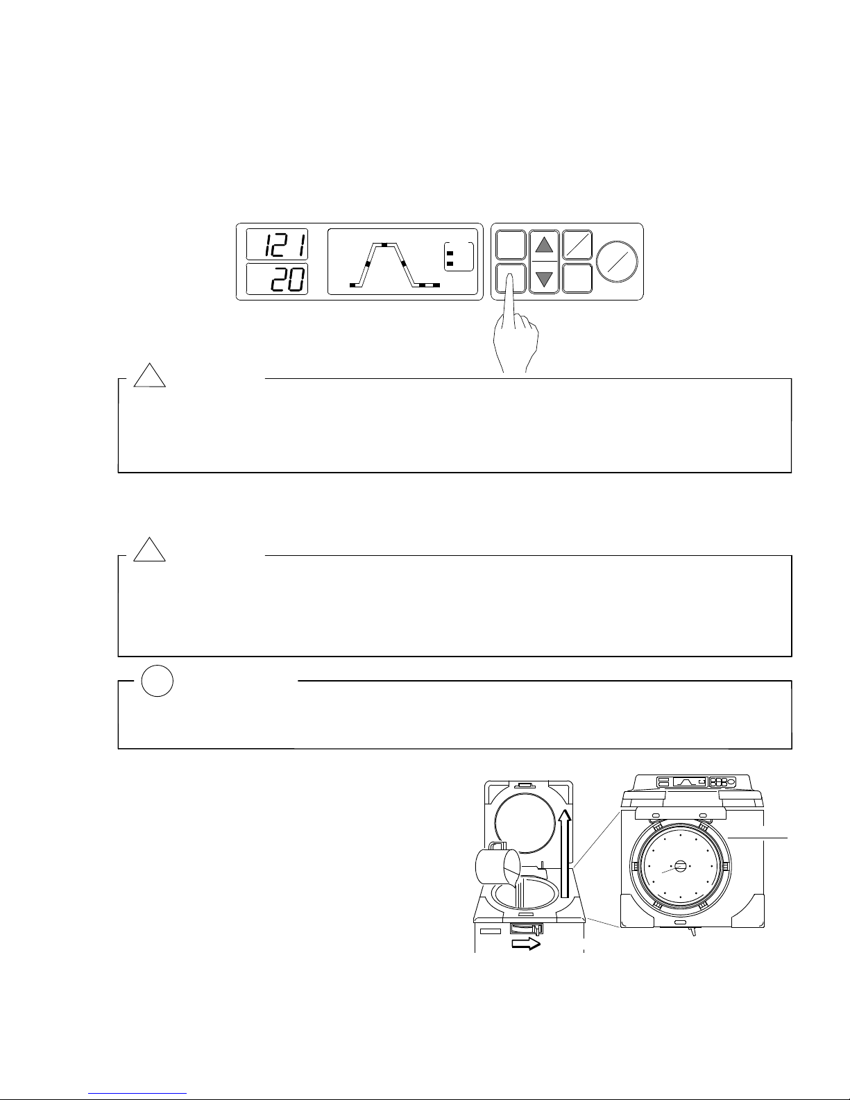
Display and Operation Switches
①Digital Display (Temperature, Error)
The digital display indicates the set temperature when the equipment is in standby and the
temperature in the working chamber during operation. When a problem occurs and an
error is detected, the display indicates the error.
②Digital Display (Time, Cooling Pattern)
The digital display indicates the set time and the set cooling pattern when the equipment is
in standby and the time remaining before completion of sterilization during operation.
③Cycle Display (ST-BY, HEATG, STER., COOL., WARM, COMP.)
All the steps included in the selected mode illuminate and the current step flashes.
④Mode Display (LIQ, SOLID)
The operation/action of the selected mode lights.
⑤MODE Switch
Selects a mode or checks a set temperature, time, or exhaust pattern.
⑥POWER ON/OFF Switch
Turns the power on or off.
⑦Set Value Increase/Decrease Switches (▲,▼)
Increase or decrease the set values.
⑧SET/ENT Switch
Used to change a set value.
⑨NEXT Switch
Selects the item for which the setting will be changed.
⑩START/STOP Switch
Used to start or stop operation.

8
Chapter 2. Installation
IMPORTANT :
If the equipment is installed in a place which is 800m or higher than sea level (i.e. under low
pressure in mountainous areas), the settings must be changed. In this case, be sure to
contact our authorized distributor in your region. Do not use the equipment before
changing.
When transporting the equipment, close the lid and slide the open/close lever to LOCK side
(left end) to prevent the lid from opening.
●
When moving the lid, do not hold it by the handle, otherwise the lid may become difficult to
close.
1. Installation instructions
①
Avoid installing the equipment in a place where its
body may be exposed to water or chemicals, or
where corrosive and explosive gases may be
produced neareby.
③
Avoid placing the equipment directly under a fire
detector. If you open the lid immediately after
completion of operation, steam comes out of the
working chamber, and may activate the detector.
④
Arrange the equipment with a clearance of 10 cm
or wider on the right side and 12 cm or wider on
the rear side to prevent the vent hole from
being blocked.
12cm or more
10cm or more
⑤
Avoid installing the equipment with its rear side located
near outlets or electrical appliances as steam comes
out of the exhaust port on the rear.
⑥
Avoid an installation place which is subject to impact
or vibration.
⑦
Avoid outdoor usage.
⑧
Place the unit in a level, firm place.
⑨
Avoid installing in a place which is subjected to a room
temperature of 5
℃
or below or 35
℃
or above.
②
Avoid installing the equiopment in a place which is
exposed to hight humidity, direct sunlight or much
dust.
!

9
2. Installation Procedure
①Put the body on the caster stoppers to prevent it from accidentally moving.
Anchor the body as described in the following.
②Connect the power cord to a rated power supply.
・Reliably ground the grounding cable.
WARNING:
Do not forcibly bend, twist, tie, or extend the power cord. Do not place heavy objects on the
cord. A damaged cord or exposed wire may cause fire or electric shock.
Never connect the power cord to a power supply with a voltage other than the rated voltage.
Connection to such a power supply may cause fire or electric shock.
If not plugging the sterilizer into a grounded socket, ground the equipment separately
before connecting it to the power source.
Never ground to a gas pipe or vinyl chloride water service pipe.
!
Model AC220V AC230V AC240V
HVA-85 14A or more 13A or more 13A or more
HVA-110 19A or more 18A or more 17A or more
CONNECT TO RATED VOLTAGE
Black
White
Green/Yellow
Connect
to ground
(1) Set the stopper the specified distance from walls.
Specified distance L = HVA-85/110...... 67 cm or
more
(2) Push the body until the front casters roll onto the
stopper
L
Push
Right side view

10
③Pour water into the exhaust bottle.
・Add water to the exhaust bottle as described below.
(1) Unload the exhaust bottle from the body.
・Pull the bottle outwards until the top handle can be
grabbed securely. Lift the bottle out of the
autoclave using this handle.
(2) Pour water into the bottle through the water filling
port. Fill water to the reference line level.
(3) Check to make sure that the water level is at LOW
level (the lowest water level).
・If too much water has been poured in, then
place the bottle in a level sink with the side of
the water filling and drain ports facing
downwards.
Any excessive water is drained automatically
until the water level is lowered to the LOW level.
(4) Check to see that the drain valve, located at the
bottom of the exhaust bottle housing area, is
closed.
(5) Load the bottle into the area.
・Be sure to push the bottle to the end, or else an
error (E r E) will occur.
Drain port
Filling
HIGH
LOW
CLOSE
Bottole housing
Drain valve
Pouring
LOW
port
water level
level
11
④Turn the breaker ON.
Lift the circuit breaker lever on the right side of the main body.
⑤Referring to “Chapter 3, Operation Method”, open the lid and take out the accessories.
⑥Place the bottom plate in the chamber.
⑦Steam is apt to emit from the exhaust port located at the rear of the body.
Therefore, install the exhaust hose and the drain bottle in the following manner:
(1) Attach the strap and clamp loosely in use of the screw attached to the body.
(2) Pass the exhaust hose through the strap. Be careful not to clog the hose by folding.
(3) Put the hose tip about 5cm into the drain bottle, and tighten the strap.
[N.B.] Pour out the water from the drain bottle so that the hose tip does not touch
the water.
Lift
Circuit breaker
Exhaust hose
Exhaust port
Drain bottle
Screw
Strap

Chapter 3. Operation Method
Basic Operation Method
Turn the power on See "1. Power On" on page 14.
▼
Open the lid
▼See "2. Pouring Water" on page 14.
Pour water
▼
Load substance
▼See "3. Loading Substance" on page 15.
Close lid
▼
Check and select mode See "4. Selecting Mode (Process)" on page 16.
▼
Check and change set
values See "5. Changing Set Values" on page 18.
▼
Start operation See "6. Starting Operation" on page 20.
▼
Check if operation is
completed
▼
Open the lid See "7. Unloading" on page 21.
▼
Unload substance
▼
Turn the power off See "8. After Completion of Operation"on page 22
12
Upper side
UNLOCK
①
②
③
Heater cover
Water level
gauge hole
1. Power On
①Press the POWER ON/OFF switch at the front of the body.
When the open/close lever is set to “LOCK” (left side), Mode number is indicated on
the display. After 2 seconds, the display indication changes into setting values, and the
autoclave is ready in this state. When the open/close lever is set to “UNLOCK”
(anywhere other than on the left side), "Lid" and “Temperature in the working
chamber” are shown alternately on the display.
NOTE:
●If the operation switches and the lock / unlock lever are left un-operated for 30 minutes,
the power saving function starts to work so that the display board blackens except for
dots blinking at the temperature zone. For reviving the display, please press any of
the operation switches.
2. Pouring Water
CAUTION:
●Do not pour anything except for water.
●Raise the lid slowly. When an impact is added to the lid, there is fear which the hinge
of the lid damages.
IMPORTANT:
●In operation of UNLOCK/LOCK lever, never fail to put POWER switch ON.
!
POWER
ON/OFF
HEATG
STER.
ST-BY
COOL
WARM
START
NEXT
COMP.
LIQ
SOLID
SET
STOP
MODE
ENT
MODE
℃
MIN.
①Slide the open/close lever to the UNLOCK
side (right end).
②Grab the handle and lift the lid as shown in
the figure below.
③Pour water through the opening of the
chamber until you can see water through
the hole at the center of the Heater cover.
・The HVA-85 requires 4 liters and
HVA-110 requires 5 liters of water.
!
13
14
3. Loading Substance
CAUTION:
Be careful not to pinch hands when closing the lid.
Close the lid after confirming that no foreign matter is adhering to the section contacting the
lid gasket. Foreign matter in this section may cause vapor leaks.
When using a waste processing bag or other kind of bag and disinfecting, place the bag in
the metal mesh holder and insert it into the working chamber. Using the bag “as is” can
cause excessive temperatures, pressures, lack-of -water, etc.
IMPORTANT :
Check to see that the temperature in the chamber is 50°C or below before starting the next
operation (operating the open/close lever).
Be sure to use the Heater cover.
①Place the substance to be sterilized into the chamber.
②While having the handles, lid down the lid.
③Press the front-center portion of the lid down until the magnet catch is attracted to the
magnet.
④While pressing the lid, slide the open/close lever to the LOCK side (the left end).
!
!
LOCK
Magnet
Magnet
②
④
③
Catch
15
NOTE:
When sterilizing an empty deep container, lay the container on its side in the chamber so
that it will be permeated with steam. An upright position may cause insufficient sterilization.
If a waste disposal bag is used in sterilization, open the bag far enough that the bag is not
in contact with the inside surface of the chamber. Insufficient sterilization may be caused if
the bag is closed during sterilization. When the bag is opened excessively, steam is
prevented from circulating in the chamber. This may also result in insufficient sterilization.
Do not pile specimens on top of one another. When the chamber is overly packed, steam
fails to penetrate to all points, resulting in incomplete sterilization.
In sterilizing liquids such as chemicals and media, pay attention to the quantity of the liquid
in relation to its container. For an Erlenmeyer flask, the amount of chemical should be
approx. 3/4 of the capacity of the container; for a test tube, the appropriate quantity of
chemical is approx. half of the capacity of the container. Too much chemical may result in
overflow from the container during the temperature rising or cooling process.
Use container caps that are loose fitting and allow the passage of air. Containers may
break if venting is not possible.
Use the DURHAM TEST TUBE (Sample tube) with 6mm caliber or more. At the DURHAM
TEST TUBE (Sample tube) with less than 6 mm caliber, air bubble sometimes remains.
4. Selecting Mode (Process)
●The following modes are programmed in the microcomputer. Select an appropriate mode.
Mode Application
1Sterilization of agar medium (warmed for the prevention of coagulation after
sterilization).
2Sterilization of liquids, such as water, media, reagents, and liquid medicines, that
withstand high temperature, high pressure steam.
3Sterilization of tools of glass, ceramic, metal or rubber that withstand high temperature,
high pressure steam and abrupt depressurization during the exhaust process.
MODE
①Press the MODE switch.
Each time the switch is pressed, the current mode repeatedly
changes from Mode 1 to Mode 2, 3, 1... in sequence.
After 2 seconds of Mode number indication, the setting values
are displayed.
16
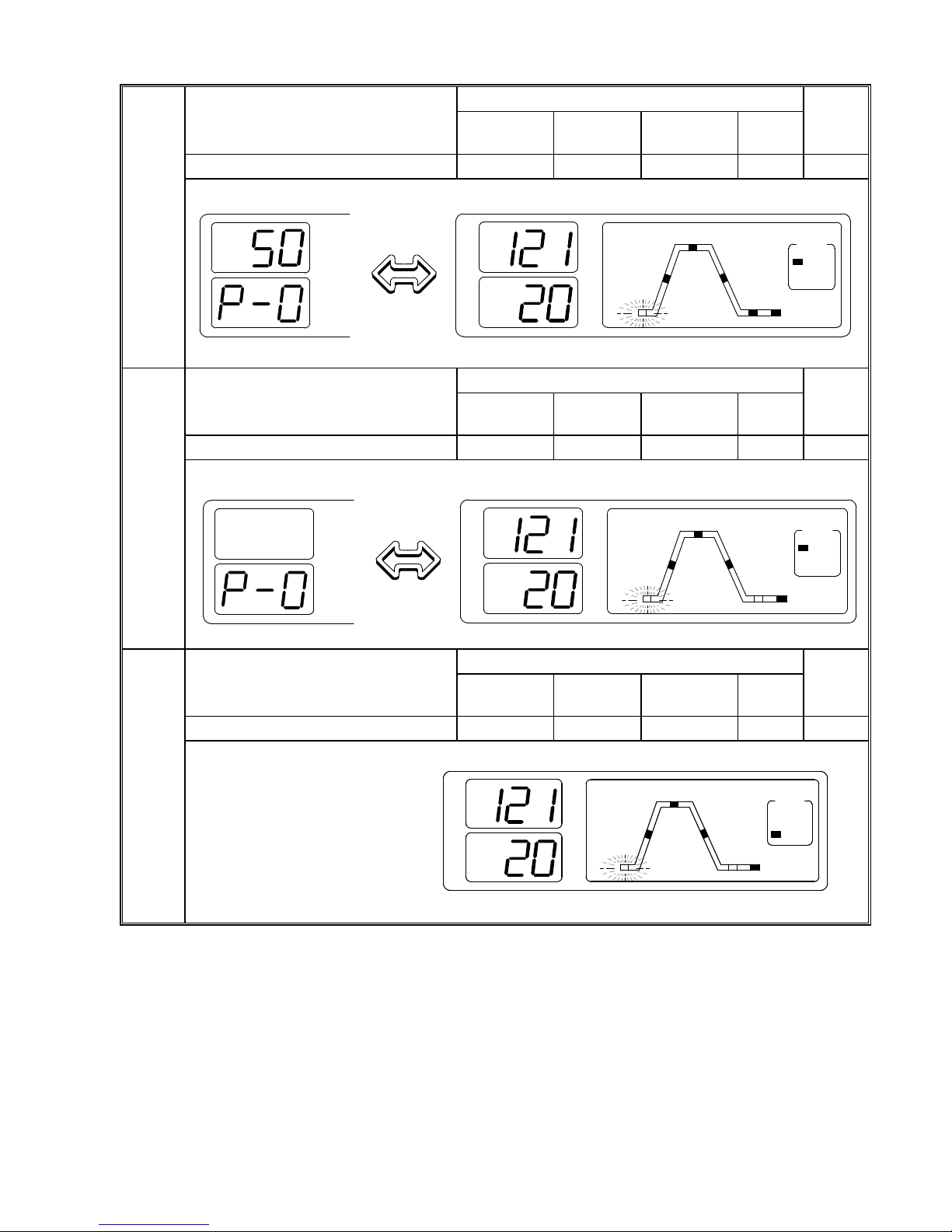
Initial Value Mode
Step Display Sterilization
Temperature
Sterilization
Time
Warming
Temperature
Cooling
pattern
Display
HEATG→STER.→COOL→WARM 121℃20 minutes 50℃P - 0 LIQ
Mode
1
Initial Value Mode
Step Display Sterilization
Temperature
Sterilization
Time
Warming
Temperature
Cooling
pattern
Display
HEATG →STER.→COOL 121℃20 minutes — P - 0 LIQ
Mode
2
Initial Value Mode
Step Display Sterilization
Temperature
Sterilization
Time
Warming
Temperature
Cooling
pattern
Display
HEATG →STER.→COOL 121℃20 minutes — — SOLID
Mode
3
Alternate
HEATG
STER.
ST
ー
BY
COOL
WARM
COMP
.
LIQ
SOLID
MODE
℃
MIN.
℃
MIN.
display
Alternate
HEATG
STER.
ST
ー
BY
COOL
WARM
COMP
.
LIQ
SOLID
MODE
℃
MIN.
℃
MIN. display
HEATG
STER.
ST
ー
BY
COOL
WARM
COMP
.
LIQ
SOLID
MODE
℃
MIN.
17
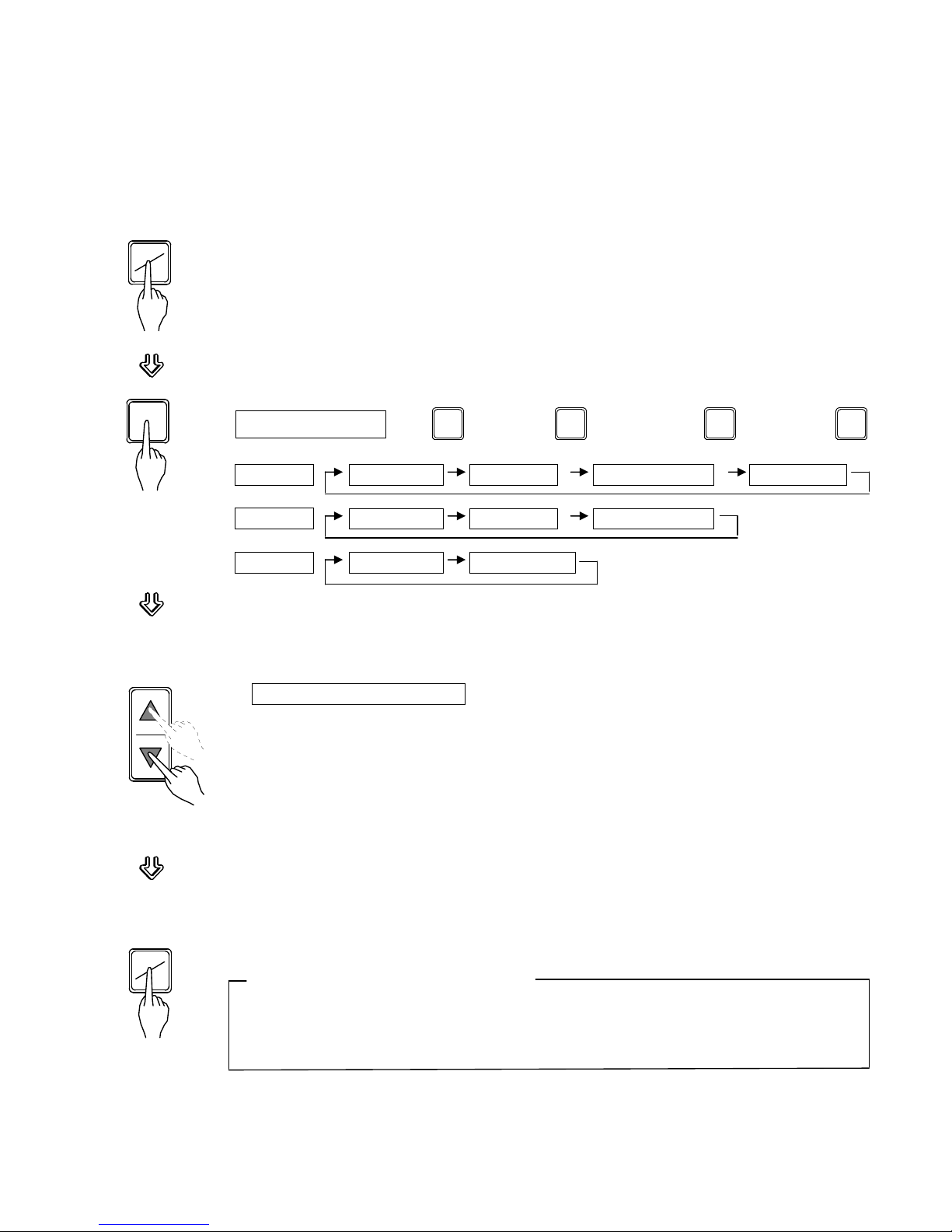
5. Changing Set Values (Registering of Values by Customer)
●Follow the steps below to change set values (sterilization temperature, sterilization time,
warming temperature, and exhaust pattern). Settings cannot be changed during operation
(after starting).
①Press the SET/ENT switch.
・The display of the set sterilization temperature will blink indicating
that the value is now changeable.
②Press the NEXT switch to select an item to change.
・Each time the switch is pressed, the item to set will change in the
sequence shown below.
▽ ▽ ▽ ▽
Mode 1 Steril.temp Steril.time Cooling pattern Warm. temp
Mode 2 Steril.temp Steril.time Cooling pattern
Mode 3 Steril.temp Steril.time
③Change the displayed value using the setting increase/decrease switches (▲,▼).
・Each time the switches are pressed, the displayed value increases or
decreases as follows:
Sterilization temperature: (In increments of 1℃within a range of:)
HVA-85/110 : 105~135℃
Sterilization time : 1 minute increments within a range of 1 - 250 minutes
Cooling pattern : Units of 1 within a range of 0 - 2
Warming temperature: 1℃increments within a range of 45 - 80℃
・If a switch is held down, the displayed value increases or decreases in 10
unit increments. When the displayed value exceeds the upper limit (lower
limit), it returns to the lower limit (upper limit).
④Press the SET/ENT switch.
・The changed value is stored and the display stops blinking and lights up.
This completes the setting operation.
Canceling Setting Value Changes
●To cancel setting changes during the change operation, press the MODE switch.
The changed values will not be stored and the equipment will return to the standby
state.
Switch Operation
NEXTNEXT
SET
ENT
SET
ENT
…
NEXT
NEXT NEXT

18
NOTE:
For sterilization of liquids, set a sterilization time longer than desired, taking a delay time
into account according to the table below.
Example)
When there is 3 liters of water in a flask, it takes nearly 30 minutes (delay time) for the
temperature of the water to reach a set sterilization temperature after the temperature in
the chamber reaches the set value. The sterilization time should therefore be set 30
minutes longer than desired in order to deal with this time delay. The sterilization time is
therefore set at 50 minutes.
Set sterilization time (50 minutes)
= Delay time (30 minutes) + desired sterilization time (20 minutes)
●If steam is abruptly exhausted after sterilization of a liquid, the liquid may gush out. To
prevent this, change the exhaust pattern setting depending on the container. When
purging manually using the fine exhaust knob, change the setting to P-0.
P-0: Cooling is not executed and equipment is left to sit. (Natural Cooling)
P-1: Pulse Cooling is executed (Cooling Fan 50 % works).
P-2: Cooling is executed (Cooling Fan 100 % works).
The mode, temperature, time, and cooling pattern are memorized even if t
he power is
cut off by the POWER ON/OFF
switch. When the power is cut by the breaker, a power
outage, or a temporary loss of power, the settings will return to the initial settings of
mode 1. Reset the setting values as desired when this occurs.
HVA-85 Reference Values of
Delay Time (per flask)
Liquid Volume Delay Time
3 liters 30 minutes
2 liters 20 minutes
1 liter 10 minutes
500cc 7 minutes
40
60
80
100
120
12
0
(Temperature)
(Time)
Set sterilization time
Delay time Sterilization time
Temperature of water
Temperature
Delay Time Reference Data
in 3 liter container
temp.
Room in working chamber

19
6. Starting Operation
①Ascertain that the water level in the exhaust bottle is between the HIGH and
LOW levels.
If above the HIGH level: See "1. Draining Exhaust Bottle" on page 26.
If below the LOW level: See "2. Installation Procedure (3)" on page 10.
②Ascertain that the water level in the drain bottle is low enough not to touch
the tip of the exhaust hose.
[N.B.] Pour out the water from the drain bottle so that the hose tip
does not touch the water.
③Confirm that the fine exhaust knob is closed.
Fine exhaust knob
④Press the START/STOP switch
・The open/close lever is locked and the lid can not be opened.
Thereafter, one of the following processes is executed depending on
the
chosen mode of operation. For details on each specific mode, see "11
Operation of Cycles" on page 23.
Mode 1 Pulse
Cooling
Warming
or
Mode 2 Air
evacuation
Sterilization Natural
Cooling
Completion
Mode 3 Forced
Cooling
Checking the Set Values during Operation
To check the set values for temperature, time, or cooling pattern during operation, press the
MODE switch. The set value remains on the display while the switch is held down. Set
values are not changeable.
OPEN
CLO SE
EXHAUST
START
STOP
This manual suits for next models
1
Table of contents
Other HIRAYAMA Laboratory Equipment manuals


