Penner Bathing Spas Dream Spa 760010-1 Guide

Dream Spa with Aqua-Aire
Installation / Assembly Instructions
760010-1, 760010-2, 770010-1, 770010-2
PENNER PATIENT CARE, INC
Box 523 / 101 Grant St.
Aurora, NE 68818
760745 Revision A –10/2/2019
1-866-PENNERS 1-866-736-6377 1-800-732-0717
E-mail Address: pennersales@Hamilton.net
Web Site: www.pennerbathingspas.com

2
Table of Contents
Table of Contents
Introduction
Terminology and Symbols Meanings
Tub Controls
Basic Dimensions
Rough in Specifications
Drain Locations
Hot and Cold Water Supply Requirements
Electrical Requirements
Unpacking the Tub
Water Supply Hose Connections
Anchoring the Tub
Electrical Connections
Water Supply and Drain Connections
Finishing up
2
3
3
4
5
6
7
8
8
9
9
10
11
11
12

3
Introduction
These instructions are for the installation of a Dream Spa tub in various configurations as
shown below in figure 1. Follow the instructions for your particular installation
configuration.
Figure 1
Terminology and Symbols Meanings
When the terms “left” or “right” are used with reference to the tub, this means left or
right as you look when seated in the tub.
Meaning: Safety warning. Failure to understand and obey this warning may
result in injury to you or to others.
Meaning: Failure to follow these instructions may cause damage to parts
or systems.
Note: Refer to the “Tub Controls” section of this manual for the location of any of the
controls referenced.

4
Hot Temp Control
Cold Temp Control
Diverter Valve
(switch between tub
fill and shower wand)
Shower Wand
Aqua-Aire
High/med/low/off
Tub Fill
Temperature Gauges
Tub Fill Temp
Shower Wand Temp
Tub Controls
The hot and cold temperature controls adjust the tub fill overall temperature. Hot temp is
limited to 110°F from the factory.
Aqua-Aire system has a three speed blower motor. First push of the air transmitter
provides full speed and aeration of spa. Second push is a medium level while a third push
is the lowest setting for blower speed. A fourth push will turn the blower motor off. There
is a time limit from the last push of the Aqua-aire transmitter where it will automatically
turn off after 20 minutes.
The Diverter Valve will select between Tub fill and the Shower wand. Both can be used at
the same time, Ex. Filling the tub while starting a rinse.
Figure 2
Comfort Warm operation control button

5
Basic Measurements
Figures 3-6

6
Rough-in Specifications
Figures 7-9

7
Figures 10-11
Figures 12-13
Drain Locations

8
Hot and Cold water supply requirements
Electrical requirements
¾” supply lines with on/off valves NPT male threads. We recommend a ¾” ball valve with ¾”
NPT male ports. (Valves supplied by others.) See figure 14-15
For optimum performance, dynamic pressures should be nominally equal between hot and
cold supplies.
Maximum static supply pressure: 145 PSI.
Maximum dynamic/maintained supply pressure: 81 PSI.
Maximum supply Hot water temperature: Consult local requirements for maximum allowed
supply temperatures. (Not recommended over 120°F).
Figure 14-15
The Dream Spa is rated 10.5 Amps at 120 Volts AC.
A 15 amp GFCI circuit is required.
The Load Center is located on the back inside wall of the Dream tub. It is supplied with a 3
foot electrical cord for a 120 V outlet. Please contact Penner Manufacturing, INC. for
further options. Best location for power supply is through the rear skirt access door. Small
cutouts through tub skirt as needed can allow for various electrical supply options. See
figure 14-15.
It is recommended that the power wires be installed by an electrician. Then
connect the Dream spa electrical cord.

9
The blower motor sits on composite board. If drain,
water supply, or electrical hook up are in this area,
the board can be moved. Use a ½” wrench or socket
and ratchet to remove the hold down nuts. Lift the
board up and move to desired location while making
sure the blower motor delivery hose doesn’t kink.
Figure 16
Unpacking the Dream Spa
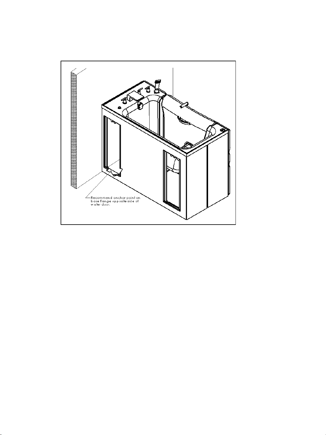
1. Remove cardboard around spa. Remove spa from pallet by unscrewing hold-
down boards from pallet. (Bower motor and composite board do not need to be
removed. Reference Figure 16)
2. Remove plastic cover and wrapping around spa.
3. Locate and save installation components. (Ex. anchor pins)
4. Remove all access doors (if applicable) and place them where they will not be
damaged during the installation process.
Water Supply Hose Connections
With an installation where the left side of the tub will be against a wall and the
water supply lines come from that wall, connect the hot and cold water lines to the
supply valves prior to moving the tub into place. The water lines uses a gasket to
make the seal. No thread tape or sealant is needed. The hose lines are female ¾”
NPT swivel ends.

10
Anchoring the tub
This anchoring procedure describes the steps for anchoring the in both
positions as shown in Figure 1 under “Dream Spa Introduction”.
1. Ensure that the electrical supply box has been wired properly. Also ensure that
the provided supply lines have been connected to the supply valves.
2. If the drain connection is to be made with a rubber coupler, it may need to be
in place (loosely on the drain pipe) prior to moving the tub into place.
3. Carefully slide the tub into the desired position.
4. There are two 5/16 x 2” anchor pins provided with the tub. Drill a 5/16” hole
through the base flange just inside the access door openings on either side of
the spa towards the front. If the floor is something other than concrete, consult
the building engineer for anchor selection. Another alternative is to place a
sturdy board across both base flanges and bolt it to the floor, pinching the tub
in place.

It is highly recommended that the electrical outlet be installed by a professional
electrician. A minimum of a 15 amp 120 volt service is required with a ground
fault circuit interrupter.
Warning: Ensure that the power supply is turned off before
attempting to wire in the power supply to the tub. Failure to do
this could result in injury or death to the installer.
When the power supply is installed and wired, take the plug-in from the Load
Center and plug it into the outlet.
The Comfort Warm control button while cycle through multiple colored lights and
go off.
If the Comfort Warm or Blower motor is on when electrical supply is first hooked
up to the tub, push the related button until system turns off. There are three heat
levels for the Comfort Warm and then an off. Also, there are three speed settings
for the blower motor, and then an off.
Comfort warm system will automatically turn off after 30 minutes.
Aqua-Aire blower motor will automatically turn off after 20 minutes.
11
Electrical Connections
Water Supply and Drain Connections
Note: It is highly recommended that a licensed plumber makes the final connections of
the hot and cold water supply and the connection to the drain.
1. Connect the supply hoses (hot and cold water supply) to the respective ports on the tub.
Ensure that there are sealing gaskets within the swivel fittings on the hoses.
2. Connect the drain (waste) of the tub to the facility’s drain system.
3. Close the water door of the tub, place the drain plug into the drain, and open the
facility’s supply valves to the tub and check for leaks.
4. Check each system (Tub fill, Hand shower, Aqua-Aire, and Comfort Warm) one at a time.
Look for leaks as it is flowing water. If not leak is found, turn off the water with your hot
and cold valves.
5. If any leaks are found, tighten the connection to stop the leak.
6. Open the tub drain and check the drain system for any leaks, and fix if needed.

12
Finishing up
If removal of the fascia pieces or access doors was necessary during installation,
reinstall those components. Apply a white silicon caulking between door cover and
door. Wipe off excess amount with damp towel or clothe. Fascia screws need to be
tightened enough to hold fascia in place, but DO NOT over tighten, as this may cause
the fiberglass to crack.
Proper care and maintenance of the Dream Spa will significantly increase the life and
usage of the spa.
Do Not attempt to operate this equipment before reviewing all the manuals and
having proper professionals install electrical and plumbing services. The use of this
equipment before proper review and installation could result in equipment damage or
injury to the spa user.
For your nearest distributor, contact:
PENNER PATIENT CARE, INC.
Box 523 / 101 Grant St.
Aurora, NE 68818
1-866-PENNERS 1-866-736-6377 1-800-732-0717
Email Address: pennersales@hamilton.net
Web Site: www.pennerpatientcare.com
This manual suits for next models
3
Table of contents
Other Penner Bathing Spas Hot Tub manuals
Popular Hot Tub manuals by other brands

Jacuzzi
Jacuzzi U961000 Installation and operation instructions

Intex
Intex PureSpa SPJ-H-20-1 owner's manual

Aquatic
Aquatic Century 30 AI6042RC30 Specification sheet

KOS
KOS Quadrat Handbook for installation, use and the maintenance

Master Spas
Master Spas INT H2X CHALLENGER 19D owner's manual

LAZBOY
LAZBOY Limited 1304 owner's manual