Pentair Pool Products UltraTemp User manual

UltraTemp®
Heat Pump
AHRI Performance Certified
Installation
and
User's Guide
IMPORTANT SAFETY INSTRUCTIONS
READ AND FOLLOW ALL INSTRUCTIONS
SAVE THESE INSTRUCTIONS

© 2011 Pentair Water Pool and Spa, Inc. All rights reserved.
This document is subject to change without notice.
1620 Hawkins Ave., Sanford, NC 27330 • (800) 831-7133 • (919) 566-8000
10951 West Los Angeles Ave., Moorpark, CA 93021 • (800) 831-7133 • (805) 553-5000
Trademarks and Disclaimers: UltraTemp®, IntelliTouch®, EasyTouch®, Eco Select™and Pentair Water Pool and Spa®are trademarks
and/or registered trademarks of Pentair Water Pool and Spa, Inc. in the United States and/or countries. Unless noted, names and
brands of others that may be used in this document are not used to indicate an affiliation or endorsement between the proprietors
of these names and brands and Pentair Water Pool and Spa, Inc. Those names and brands may be the trademarks or registered
trademarks of those parties or others.
P/N 474099 Rev. E 9/27/11
Customer Service
If you have questions about ordering Pentair Water Pool and Spa®("Pentair") replacement parts,
and pool products, please use the following contact information:
Customer Service (8 A.M. to 4:30 P.M. — Eastern and Pacific Times)
Phone: (800) 831-7133
Fax: (800) 284-4151
Technical Support
Sanford, North Carolina (8 A.M. to 4:30 P.M. — Eastern Time)
Phone: (919) 566-8000
Fax: (919) 566-8920
Moorpark, California (8 A.M. to 4:30 P.M. — Pacific Time)
Phone: (805) 553-5000
Fax: (805) 553-5515
Web site
visit www.pentairpool.com or www.staritepool.com to find information about Pentair products

UltraTemp®Heat Pump Installation and User’s Guide
i
Contents
Important Warning and Safety Instructions..........................................................................iii
Section 1: Introduction......................................................................................................1
Heat Pump Overview ...............................................................................................1
General Features .....................................................................................................2
Section 2: Installation........................................................................................................3
Installation................................................................................................................3
Materials Needed for Installation .............................................................................3
UltraTemp®Heat Pump Dimensions ........................................................................4
Location ...................................................................................................................4
Clearances...............................................................................................................5
Roof Run-off.............................................................................................................5
Equipment Pad.........................................................................................................5
Drainage and Condensation ....................................................................................6
Lawn Sprinklers .......................................................................................................6
Anchor Clamp Installation ........................................................................................6
Water Connections...................................................................................................7
Standard Plumbing ..................................................................................................7
Water Connections (Quick Connect)........................................................................8
Automatic Flow Control Valve ..................................................................................8
Multiple Unit Installation ...........................................................................................9
Heat Pump, Heater and/or Solar Combination.........................................................9
Multiple Heat Pump Connections.............................................................................10
Electrical Connections .............................................................................................11
General Information .................................................................................................11
Main Power ..............................................................................................................11
Bonding....................................................................................................................11
Remote Operation....................................................................................................12
Relay Remote Controls ............................................................................................12
Connecting the Heat Pump to IntelliTouch®or EasyTouch® Load Center
via the Heat Pump Spade Terminals........................................................................13
Connecting the Heat Pump to IntelliTouch®or EasyTouch® Load Center
via RS-485 Connector..............................................................................................14
Connecting the Heat Pump Control Board to IntelliTouch®or EasyTouch®
via RS-485 Connector..............................................................................................14
Pin Configuration for the Heat Pump Control Board to IntelliTouch®.......................15
Connecting the IntelliTouch®or EasyTouch® to the Heat Pump ...............................15
Water Pressure Switch Adjustment..........................................................................16

ii
UltraTemp®Heat Pump Installation and User’s Guide
Contents
Section 3: Operating the Heat Pump ...............................................................................17
Initial Start-up Precautions.......................................................................................17
Heat Pump Control Panel Overview ........................................................................18
Control Panel Layout................................................................................................18
Control Panel Operation...........................................................................................19
Timers and Delays ...................................................................................................23
Control Panel Menu Tree Screens ...........................................................................24
Control Panel Menu Screens ...................................................................................25
Operator Setup Menu Tree Screens ........................................................................27
Operator Setup Menu Screens ................................................................................28
Locking the Control Panel ........................................................................................29
Defrost Cycle ...........................................................................................................29
AutoSet ....................................................................................................................30
Control Panel Alarm Messages ...............................................................................31
Heat Pump Wiring Diagram – (Single Phase – 50/60 Hz) .......................................32
Heat Pump Wiring Diagram – (Three Phase – 60 Hz) .............................................33
Heat Pump Wiring Diagram – (Three Phase – 50 Hz) .............................................34
AutoSet Contactor to Mechanical Timer Wiring Example ........................................35
Section 4: General Maintenance ......................................................................................36
Water Chemistry ......................................................................................................36
Winterizing ...............................................................................................................36
Spring Start-Up ........................................................................................................37
Inspection and Service ............................................................................................37
Owner Inspection .....................................................................................................37
Professional Maintenance and Service....................................................................38
Section 5: Troubleshooting .............................................................................................39
Temperature Resistance Chart Table ......................................................................42
Ambient/Water Flow Table for Professional Maintenance and Service ...................43
Section 6: Replacement Parts ........................................................................................44
Illustrated Parts (UltraTemp®)...................................................................................44
Replacement Parts List (UltraTemp®).......................................................................45

UltraTemp®Heat Pump Installation and User’s Guide
iii
IMPORTANT WARNING AND SAFETY INSTRUCTIONS
Codes and Standards
UltraTemp®heat pumps are listed by ETL as complying with the latest edition of the “UL Standard for Safety for Heating
and Cooling Equipment”, UL 1995 and CSA C22.2 No. 236.
All Pentair heat pumps must be installed in accordance with the local building and installation codes as per the utility or
authority having jurisdiction. All local codes take precedence over national codes. In the absence of local codes, refer
to the latest edition of the National Electric Code (NEC) in the United States and the Canadian Electric Code (CEC) in
Canada for installation.
DANGER — Risk of electrical shock or electrocution.
The electrical supply to this product must be installed by a licensed or certified electrician in
accordance with the National Electrical Code and all applicable local codes and ordinances.
Improper installation will create an electrical hazard which could result in death or serious
injury to pool or spa users, installers, or others due to electrical shock, and may also cause
damage to property. Read and follow the specific instructions inside this guide.
WARNING — To reduce the risk of injury, do not permit children to use this product unless they are closely
supervised at all times.
WARNING — For units intended for use in other than single-family dwellings, a clearly labeled emergency
switch shall be provided as part of the installation. The switch shall be readily accessible to
the occupants and shall be installed at least 5 feet [1.52 m] away, adjacent to, and within sight
of the unit.
Important Notice:
This guide provides installation and operation instructions for the UltraTemp®Heat Pump.
Consult Pentair with any questions regarding this equipment.
Attention Installer: This guide contains important information about the installation, operation and safe use of this
product. This information should be given to the owner and/or operator of this equipment after installation or left on or
near the heat pump.
Attention User: This manual contains important information that will help you in operating and maintaining this
heat pump. Please retain it for future reference.
WARNING — Before installing this product, read and follow all warning notices and instructions which are
included. Failure to follow safety warnings and instructions can result in severe injury, death, or
property damage. Call (800) 831-7133 for additional free copies of these instructions.

iv
UltraTemp®Heat Pump Installation and User’s Guide
IMPORTANT WARNING AND SAFETY INSTRUCTIONS
Consumer Information and Safety
The UltraTemp®series of heat pumps are designed and manufactured to provide safe and reliable service when installed,
operated and maintained according to the information in this manual and the installation codes referred to in later sections.
Throughout the manual, safety warnings and cautions are identified by the “ “ symbol. Be sure to read and comply with
all of the warnings and cautions.
WARNING — The U.S. Consumer Product Safety Commission warns that elevated water temperature can be
hazardous. See below for water temperature guidelines before setting temperature.
WARNING — The following “Safety Rules for Hot Tubs” recommended by the U.S. Consumer Product Safety
Commission should be observed when using the spa.
1. Spa or hot tub water temperatures should never exceed 104° F. [40° C.]. A temperature of 100° F. [38° C.] is considered
safe for a healthy adult. Special caution is suggested for young children. Prolonged immersion in hot water can induce
hyperthermia.
2. Drinking of alcoholic beverages before or during spa or hot tub use can cause drowsiness which could lead to
unconsciousness and subsequently result in drowning.
3. Pregnant women beware! Soaking in water above 100° F. [38° C.] can cause fetal damage during the first three
months of pregnancy (which may result in the birth of a brain-damaged or deformed child). Pregnant women should
stick to the 100° F. [38° C.] maximum rule.
4. Before entering the spa or hot tub, the user should check the water temperature with an accurate thermometer.
Spa or hot tub thermostats may err in regulating water temperatures.
5. Persons with a medical history of heart disease, circulatory problems, diabetes or blood pressure problems should
obtain their physician’s advice before using spas or hot tubs.
6. Persons taking medication which induce drowsiness, such as tranquilizers, antihistamines or anticoagulants should
not use spas or hot tubs.
Hyperthermia occurs when the internal temperature of the body reaches a level several degrees above normal body
temperature of 98.6° F. [37° C.]. The symptoms of hyperthermia include: drowsiness, lethargy, dizziness, fainting, and an
increase in the internal temperature of the body.
The effects of hyperthermia include:
1. Unawareness of impending danger.
2. Failure to perceive heat.
3. Failure to recognize the need to leave the spa.
4. Physical inability to exit the spa.
5. Fetal damage in pregnant women.
6. Unconsciousness resulting in danger of drowning.
Warranty Information
Heat pumps are sold with a limited factory warranty. Details are specified on the warranty card. Make all warranty claims
to an authorized Pentair dealer or directly to the factory. Claims must include the heat pump serial number and model (this
information can be found on the rating plate), installation date, and name of the installer. Shipping costs are not included in
the warranty coverage. This warranty does not cover damage caused by improper assembly, installation, operation, improper
water chemistry balancing or other chemical abuse, or improper sanitation application, winterizing, field modification, or
failure to earth bond and properly ground the unit. Any changes to the heat pump, evaporator, heat exchanger, wiring, or
improper installation may void the warranty.

UltraTemp®Heat Pump Installation and User’s Guide
v
IMPORTANT WARNING AND SAFETY INSTRUCTIONS
Swimming Pool Energy Saving Tips
It is important to note that a heat pump will not heat a pool as fast as a large gas or electric pool heater. If the pool water
is allowed to cool significantly, it may take several days to return to the desired swimming temperature. For weekend use,
it is more economical to maintain the pool water temperature at or near your desired swimming temperature. If you do not
plan to use your pool for a prolonged period, then you might choose to turn the heat pump completely off or decrease the
temperature setting of the control several degrees to minimize energy consumption.
Pentair offers the following recommendations to help conserve energy and minimize the cost of operating your heat pump
without sacrificing comfort.
1. The American Red Cross recommends a maximum water temperature of 78° F. [25° C.]. Use an accurate pool thermometer.
A difference of 4° F. [2° C.] , between 78° F. and 82° F. [26° C. and 28° C.], will significantly increase energy consumption.
2. Carefully monitor the water temperature of your pool in the summertime. You can reduce heat pump usage due to
warmer air temperatures.
3. During the winter or when on vacation for longer than a week, turn off the heat pump.
4. Find the proper setting on the heat pump temperature control and use the Keypad Lock function to discourage further
adjustments.
5. Where possible, shelter the pool from prevailing winds with well-trimmed hedges or other landscaping, cabanas, or
fencing.
6. Pentair recommends the use of a pool cover. Besides providing a valuable safety feature, a pool cover will reduce heat
loss, conserve chemicals, and reduce the load on filter systems.
Technical Information
HEAT PUMP PRESSURE DROP
0
1
2
3
4
5
6
7
8
9
10
0 10 20 30 40 50 60 70 80 90 100 110 120
Water Flow (gpm)
Pressure Drop (psi)
UltraTemp 90, 100I
UltraTemp 110
UltraTemp 120
UltraTemp 120C
UltraTemp 120H/C
UltraTemp 90I

vi
UltraTemp®Heat Pump Installation and User’s Guide
IMPORTANT WARNING AND SAFETY INSTRUCTIONS
General Installation Information
1. Installation and service must be performed by a qualified installer or service agency, and must conform to all
national, state, and local codes.
2. UltraTemp®heat pumps get electrical power from an external source and provide a dual electronic thermostat
control system for pool/spa combinations or preheat convenience.
3. This heat pump is specifically designed for heating fresh water swimming pools and spas. Do not use it as a general
service heater. Consult your dealer for the appropriate Pentair products for these applications.
General Specifications
Installation Location Certified for use:
OUTDOOR USE ONLY. Failure to provide the proper clearances outlined on page 5 will lower the
performance of the heat pump and void the warranty.
Water Pipe/Heater Connection — Plastic 2” PVC (Unions included)
Flow Rate
Maximum 100 gpm [380 lpm]
Minimum 30 gpm [110 lpm]
Maximum Working Water Pressure 50 psi
Electrical Supply – Voltage Requirements:
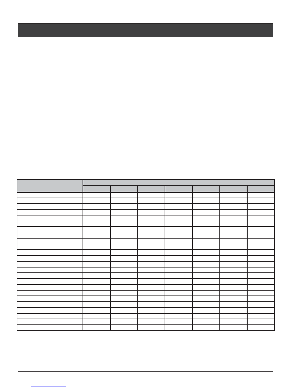
* 80A-80RH-80W: 80° F Air Temp, 80% RH, 80° F Water Inlet Temp.
** 80A-62RH-80W: 80° F Air Temp, 62% RH, 80° F Water Inlet Temp.
*** 50A-63RH-80W: 50° F Air Temp, 63% RH, 80° F Water Inlet Temp.
**** Add 50 lbs. for Pallet and Packaging.
COP = Coefficient of Performance
90 110 120 120 H/C 120C 100I 90I
Voltage/Phase/Hz 208-230/1/60 208-230/1/60 208-230/1/60 208-230/1/60 208-230/3/60 230/1/50 380-400/3/50
Min. Circuit Ampacity (Amp) 40 42 42 42 35 42 18
Recommended Fuse Size 50 50 50 50 50 50 30
Max Fuse Breaker Size 60 70 70 70 60 60 40
Compressor/Fan Motor/System
RLA
Compressor/Fan Motor/System
LRA
Compressor/Fan Motor/System
MCC
Capacity (Btu/h) 80A-80RH-80W * 90,000 108,000 125,000 125,000 125,000 102,000 85,000
COP 80A-80RH-80W * 5.8 5.8 5.5 5.4 5.7 5.95.7
Power Input (KW) 80A-80RH-80W* 4.5 5.5 6.7 6.8 6.4 5.1 4.4
Current (Amp) 80A-80RH-80W* 21 25 30 31 1925 9
Capacity (Btu/h) 80A-62RH-80W ** 84,000 101,000 117,000 117,000 115,000 96,000 81,000
COP 80A-62RH-80W ** 5.5 5.5 5.3 5.2 5.3 5.6 5.4
Power Input (KW) 80A-62RH-80W** 4.5 5.4 6.5 6.6 6.2 54.4
Current (Amp) 80A-62RH-80W** 20 25 2930 18 24 9
Capacity (Btu/h) 50A-63RH-80W *** 60,000 72,000 82,000 82,000 81,000 67,000 56,000
COP50A-63RH-80W*** 4444444
Power Input (KW) 50A-63RH-80W*** 4.2 5.3 6 6 5.94.94.1
Current (Amp) 50A-63RH-80W*** 1924 27 27 17 24 9
Weight (lbs) **** 250 270 270 278 280 280 250
Shipping Size (LxWxH) incl. Pallet 43"x34"x39" 43"x34"x51" 43"x34"x51" 43"x34"x51" 43"x34"x51" 43"x34"x47" 43"x34"x39"
26/2/28
19/NA/NA
Models
31/2/33 32/2/34 32/2/34
UltraTemp
®
32/2/34
87/3/90
32/2/34 12/1/13
178/4/182
49/NA/NA 50/NA/NA 50/NA/NA 50/NA/NA 39/NA/NA 50/NA/NA
148/4/152 185/4/189185/4/189190/4/194 130/4/134

UltraTemp®Heat Pump Installation and User’s Guide
1
Section 1
Introduction
Overview
Your Pentair heat pump will provide you with years of heated pool enjoyment. Heat pumps operate by
taking heat from the surrounding air and transferring it into the water. The warmer the air and the more
humidity in the air, the more latent heat is available for heating your pool. With a properly sized heat
pump for your pool, the heat pump should raise your pool on average 1° F. per hour depending on air
temperature, humidity, and water temperature. The ideal or rated condition for the heat pump is 80°
F air temperature, 80% relative humidity, and 80° F water temperature. As conditions decrease from
80/80/80, the heat pump performance will decrease slightly.
Heat Pumps are best utilized to maintain a set water temperature; they are not intended to provide instant
or fast heating. It is not reasonable to expect a heat pump to perform like a gas heater which has a much
higher BTU output and faster response. Additionally, gas heaters are not dependent on environmental
conditions. Swimming pool heat pumps are very similar to home heating and air conditioning heat
pumps and therefore should be treated similarly.
Proper operation and use of the heat pump is to set it at your desired temperature and leave it.Your heat
pump will turn on and off automatically to maintain your desired temperature much like your home
HVAC unit. To take advantage of the sun’s energy, operate your heat pump during the heat of the day.
Your heat pump will still operate when the temperature drops at night, but the output will be decreased.
It is acceptable to shut the heat pump off and not use it for extended periods of time. When you have a
need to heat your pool, please plan accordingly since it may take the heat pump days to heat your pool
back to your desired temperature, depending on your pool temperature and environmental conditions.

2
UltraTemp®Heat Pump Installation and User’s Guide
General Features
• Dual digital thermostats offer precise temperature control to maintain the desired separate water
temperatures in pool/spa combinations without overheating or wasting energy.
• Long-life corrosion resistant composite plastic cabinet stands up to severe climates and pool
chemicals.
• 100% pure titanium heat exchanger assures corrosion-free performance for extra long life.
• Self-diagnostic control panel monitors and troubleshoots heat pump operations to ensure safe,
dependable operation.
• LCD control board displays an intuitive menu-driven read out with easy to follow full word
messages- no more codes.
• Autoset (time clock over-ride) feature monitors water temperature and turns the water circulation
pump on and off as needed to maintain desired pool temperatures.
• Automatic defrost feature senses refrigerant temperature and prevents the heat pump from
freezing, allowing the heat pump to operate at even lower temperatures.
• Compatible with all automated control packages.
• Thermostatic expansion valve (TXV) controls refrigerant flow for optimum efficiency and BTU
output over a wider operating range.
• Each unit undergoes a finishing process to ensure corrosion resistance and long life.
• Elevated base pan for positive drainage of condensation.
• 2-inch plumbing connections for easy installation.
• Separate isolated electrical compartment prevents internal corrosion, extends heater life.
• RS485 communication compatible with IntelliTouch®and EasyTouch®control systems.
• Highest efficiency available, meets or exceeds existing codes and standards.
• Adjustable timer allows to set the heat pump to run for a predetermined time. Incremental by 10
minutes to a maximum of 99 hours.
• Ability to display text in Spanish.
• ETL listed for safe operation.
• AHRI Performance Certified.

UltraTemp®Heat Pump Installation and User’s Guide
3
Section 2
Installation
The following general information describes how to install the UltraTemp®heat pump.
Installation
Only a qualified service person should install the heat pump. Before installing this product, read
and follow all warning notices and instructions on pages iii-vi.
Materials needed for Installation
The following items are needed and are to be supplied by the installer for all heat pump installations:
1. Plumbing connections (2 inch).
2. Level surface for proper drainage.
3. Suitable electrical supply line. See rating plate on unit for electrical specifications.Ajunction box is
not needed at the heat pump; connections are made inside of the heat pump electrical compartment.
Conduit may be attached directly to the heat pump jacket.
4. Electric cutout switch that will interrupt all power to the unit. This switch must be within line of
sight of the heat pump.
5. Watertight conduit to run the electrical supply line.
Note: We recommend installing isolation valves on the inlet and outlet water connections for
ease of serviceability.

4
UltraTemp®Heat Pump Installation and User’s Guide
UltraTemp®Heat Pump Dimensions
Correct installation is required to assure safe operation. The requirements for Pentair heat pumps include
the following:
• Dimensions for critical connections.
• Field assembly (if required).
• Appropriate site location and clearances. (See pages 4-5).
• Proper electrical wiring. (See pages vi and 11, 32-34).
• Adequate water flow. (See page vi).
This manual provides the information needed to meet these requirements. Review all application and
installation procedures completely before continuing the installation.
Location
CAUTION — When pool equipment is located below the pool surface, a leak from any component can cause large
scale water loss or flooding. Pentair Water Pool and Spa, Inc. cannot be responsible for such water
loss or flooding which may cause damage to the product.
Avoid placing the heat pump in locations where it can cause damage by water or condensate leakage.
If this is not possible, provide a suitable drain pan to catch and divert any leakage.
38.7"
(983 mm)
4.5"
(114 mm)
9.25"
(235 mm)
11.25"
(286 mm)
A
34.0"
(864 mm)
32.0"
(813 mm)
30.7"
(780 mm)
MODEL # / ULTRATEMP®
90 100 120 120 H/C 120C 100I 90I
Dimension “A” 33.5”
(851 mm)
45.5”
(1156 mm)
45.5”
(1156 mm)
45.5”
(1156 mm)
45.5”
(1156 mm)
41.5”
(1054 mm)
33.5”
(851 mm)
Figure 1.

UltraTemp®Heat Pump Installation and User’s Guide
5
Clearances
All criteria given in the following sections reflect minimum clearances. However, each installation must
also be evaluated, taking into account the prevailing local conditions such as proximity and height of
walls, and proximity to public access areas.
The heat pump must be placed to provide clearances on all sides for maintenance and inspection.
1. At least 24 in. [610 mm] access must be available in the front and 12 in. [30.5 mm] on all the other
sides of the heat pump for service and proper air flow, see Figure 2.
2. If the heat pump is to be installed under a cover or under a vertical overhang, the unit must have a
minimum of five (5) feet [1520 mm] clearance from the top of the heat pump.
3. Install a minimum of five (5) feet [1.52 m] from the inside wall of the pool or spa unless the heat
pump is separated from the pool or spa by a five (5) foot high solid fence or other permanent barrier.
Canadian installations require a minimum of three (3) meters from pool water.
Roof Run-off
Make sure the heat pump is not located where large amounts of water may run-off from a roof into
the unit. Sharp sloping roofs without gutters will allow massive amounts of rain water, mixed with
debris from the roof to be forced through the unit, see Figure 2. A gutter or down spout may be
needed to protect the heat pump.
Equipment Pad
Place the heat pump on a flat slightly pitched surface, such as a concrete or fabricated slab (pad). This
allows proper drainage of condensation and rain water from the base of the unit. If possible, the pad
should be placed at the same level or slightly higher than the filter system equipment pad.
NOTE: Ensure that the pad is pitched not more than 1/4 in. per foot toward the compressor end
(front) of the heat pump. Pitch slab from back to front 1/4 in. per foot maximum and level from
side to side.
Figure 2.
EVAPORATOR
COILS
5 FT
(1520 mm)
3"
(76 mm)
OPEN
OVER HANG
AIR FLOW OUT
AIR
FLOW
IN
SLAB
SERVICE
ACCESS
24"
(610 mm)
12"
(305 mm)
12"
(305 mm)
12"
(305 mm)

6
UltraTemp®Heat Pump Installation and User’s Guide
Drainage and Condensation
Condensation will occur from the evaporator coil while the unit is running and drain at a steady rate,
usually three to five gallons per hour, depending upon ambient air temperature and humidity. The more
humid the ambient conditions, the more condensation will be produced. The bottom of the unit acts as a
tray to catch rainwater and condensation. Keep the drain holes, located on the bottom pan of the base of
the unit, clear of debris.
Lawn Sprinklers
Make sure there are absolutely no sprinkler heads near the heater that will
in any way spray on or into the heater. Sprinkler damage is not covered
under the warranty agreement.
Make sure that they’re a sufficient distance away so that normal winds will
not carry the mist to the heater. If your filtering system area has plants that
needwater,use atrickle typeirrigation sprinklerinstead ofthe broadcasttype.
The heater is designed to handle the wettest weather conditions that are
typical of rain and humidity, etc. Sprinkler heads force high pressure water
into the unit from the side at an odd angle. Most sprinkler systems are
connected to a well system.
Most well water ishigh in minerals, sulphur andother aggressive contaminates.These contaminates will
leave a build up on the evaporator coils and electronics causing corrosion and hamper the efficiency.
If you are located within 15 miles of the coast, salt may also be in the well water.
Anchor Clamp(s) Installation
In Florida, building codes require that the heat pump be anchored to the equipment pad or platform
to withstand high wind pressures created during hurricanes.
This heat pump is provided with anchor clamps designed to hold the unit to the equipment pad
in high wind conditions. Installation of the anchor clamps is recommended in all installations.
Installation of the anchor clamps is required in Florida (See Florida Building Code 301.13).
To install the anchor clamps:
1. Be sure that the heat pump is in its permanent location on the equipment pad.
2. Remove the anchor clamps from the installation and instruction package.
Note: Bolts and bolt anchors are not included with the heat
pump. The installer must provide 1/4” x 1-3/8” stainless steel
anchorboltsandtheappropriatesizeconcreteanchortomount
the clamp to the equipment pad.
3. Place the clamps at the base of the heat pump in the 4
locations indicated in Figure 4, (2 in. undercut [notched
area] on either side).
4. Fit the hook of each clamp over the lip on the base panel
of the heat pump. The hook should fit between the lip of
the base panel and the evaporator coil guard, see Figure 5.
5. Marktheposition oftheholein eachclamponthe equipment pad. Figure 4.
Heat Pump
Clamps
Heat Pump
Clamps
NO SPRINKLERS
NO SPRINKLERS
NO SPRINKLERS
WITHIN A
6 FT. RANGE
Figure 3.

UltraTemp®Heat Pump Installation and User’s Guide
7
HEAT PUMP
CHEMICAL FEEDER
TO POOL OR SPA
POOL PUMP
FROM POOL OR SPA
FILTER
MANUAL BYPASS VALVE
(Optional)
Figure 6. Standard Plumbing Layout
Anchor Clamp(s) Installation, continued
6. Use a masonry drill bit and drill a hole in the cement
with a diameter as determined by the concrete anchor,
at each of the marks on the equipment pad. The hole
should be approximately 1½ in. deep.
7. Insert a bolt anchor into each of the holes. Be sure the
anchors are set completely into the holes
8. Positiontheanchorclampssothattheholesintheclamps
are over the bolt anchors. Be sure that the clamp hooks
are over the lip of the heat pump base, see Figure 5.
9. Insert an anchor bolt through each clamp into the anchor
and tighten to secure the clamp and heat pump to the
equipment pad.
Water Connections
Plumbing layout
Figure 6 illustrates the standard plumbing layout with a single heat pump unit. Follow the diagram from
right to left, the plumbing sequence is as follows:
Note: For normal installations, do not install a shut-off valve or any kind of variable restriction
in the water piping between the heat pump outlet and the pool/spa.
The heat pump must be protected from back-siphoning of water. Be sure to provide an optional manual
bypass valve between the pool and the heat pump outlet to protect from back-siphoning.
Arrangement of pool system components (other than Figure 6 and following diagrams) can affect the
operation of the heat pump’s water pressure switch. Location of the heat pump above or below the pool
water surface can also affect operation of the switch.
In general, the pressure switch can be adjusted to accommodate this effect if the heat pump water
connections are no more than six (6) feet below the pool water surface or no more than fifteen (15) feet
above it. See instructions for pressure switch adjustment (page 16) in the heat pump start-up section
of this manual for more information. If the heat pump is installed outside of this range, an external
pressure switch may need to be installed in the plumbing upstream of the heat pump. Call the Pentair
Heat Pump Technical Service department at (800) 831-7133 for details.
Be advised that when pool equipment is located below the pool surface a leak can result in large-scale
water loss or flooding. Pentair cannot be responsible for such water loss or flooding or the damage
caused by either occurrence.
Pool > Skimmer and Main Drain > Pool Pump > Filter > Heat Pump > Chlorinator > Pool
HEAT PUMP
ANCHOR CLAMP
AIR COIL GUARD
AIR
COIL
BOLT ANCHOR
(installer provided)
HEAT PUMP
BASE
1-3/8" HEX BOLT
(installer provided)
CONCRETE
EQUIPMENT PAD
Figure 5.

8
UltraTemp®Heat Pump Installation and User’s Guide
Water Connections at the Heat Pump
CAUTION — Make sure that flow requirements and pool water turnover rates can be maintained with the installation
of additional heat pumps and plumbing restrictions.
Two inch Quick Connect fittings have been installed on the water inlet and outlet connections, see
Figure 7. Filtered cool water is plumbed to the inlet, located on the right side of the heat pump. Heated
water flows through the outlet, located on the left side of the heat pump.
Plastic piping (PVC Schedule 40) should be connected to the heat pump. The unions, provided with
the unit, accept 2 in. PVC pipe.
Automatic Flow Control Valve
The inlet/outlet header of the heat pump comes equipped with an internal automatic flow control valve.
The automatic flow control valve maintains the proper flow through the heat pump at rates up to 100
gpm (380 lpm). If the filter system flow rate is higher than 100 gpm (380 lpm), install a manual bypass
valve, see Figure 6 on page 7.
NOTE: Be advised that if your circulation pump is over 2 HP or if the total flow exceeds 100 gpm
(380 lpm), you will have to add an external bypass valve. Excess water flow will damage the heat
exchanger.
Figure 7.
Water
Outlet Union
Water
Inlet Union

UltraTemp®Heat Pump Installation and User’s Guide
9
Multiple Unit Installation
Heat Pump, Heater and/or Solar Combination
In certain regions of the country it may be more economical to run a heat pump during the warmer
months and a gas heater during the cooler months. In some situations it may be desirable to run the heat
pump in the “Chiller” mode, if so equipped, during the hottest portion of the year and a heater during
the cooler months. The Pentair heat pump may be used in conjunction with a gas or electric heater or
any combination of heat sources including solar. All heat sources must be plumbed in series to work
correctly and efficiently.
A recommended plumbing layout for a heat pump / heater / solar combination heating system for a
pool / spa combination is shown in Figure 8. Your system may not contain all of these components,
but the basic plumbing will apply by eliminating the component in the illustration that is not a part of
your system.
HEATER
EAT P
U
M
P
FROM SOLAR
T
O
SO
LA
R
FILTE
R
S
DRAIN
P
OOL
DR
A
S
P
A
INTAKE
P
OOL
INTAKE
SP
A
RETURN
P
OOL
RET
U
R
N
S
P
A
M
AKE-U
P
VALVE
C
HE
C
K
24"
Figure 8.
(610 mm)
Figure 8.

10
UltraTemp®Heat Pump Installation and User’s Guide
24 inches (610 mm) min. clearance around evap.
Extend 12" (305 mm)
past end heater
inlet for hydraulic
balancing
Extend 12" (305 mm)
past end heater
inlet for hydraulic
balancing
Pool Pump
Flow Meter
Minimum
2" PVC Pipe
2" PVC Pipe
Flow Meter
To Pool
OPTIONAL
2" Check Valve Bypass
Check Valves are
optional on heater inlets
but will help system
balancing
24"
(610 mm)
24 inches (610 mm) min. clearance around evap.
Extend 12"
(305 mm) past
end heater
inlet for hydraulic
balancing
Extend 12" (305 mm)
past end heater
inlet for hydraulic
balancing
Pool Pump
Flow Meter
Minimum
3" PVC Pipe
2" PVC Pipe
Flow Meter
To Pool
3" Ball Valve Bypass
Check Valves are
optional on heater inlets
but will help for system
balancing
24"
(610 mm)
2" PVC Pipe2" PVC Pipe
2" PVC Pipe
3" PVC Pipe3" PVC Pipe
60 GPM (220 lpm)
Minimum
120 GPM (440 lpm)
Minimum
Multiple Heat Pump Connections
All plumbing on multiple heat pump installations must be done in parallel see Figures 9 and 10. An
equal flow of water to each heat pump is important for optimum operation.
NOTE: It may be necessary to adjust the water pressure switch if a unit is installed below the
water level. See page 16 for details on when and how to adjust the pressure switch.
Each heat pump allows a maximum flow rate of 100 gpm (380 lpm) and requires a minimum of
30 gpm (110 lpm).
Figure 9. Two Heat Pump Plumbing Layout
Figure 10. Four Heat Pump Plumbing Layout

UltraTemp®Heat Pump Installation and User’s Guide
11
Electrical Connections
WARNING — Risk of electrical shock or electrocution.
This heat pump contains wiring that carries high voltage. Contact with these wires could result in
death or serious injury to pool or spa users, installers, or others due to electrical shock, and may also
cause damage to property. Always disconnect power circuit before connecting the heat pump.
CAUTION — Label all wires prior to disconnection when servicing controls. Wiring errors can cause improper and
dangerous operation. Verify proper operation after servicing.
General Information
Wiring connections must be made exactly as shown in the wiring diagram found on the inside of the
heat pump access panel, see Figures 18-20 on pages 32-34. The heat pump must include a definite
means of grounding and bonding. There is a ground lug inside the heat pump electrical compartment
and a bonding lug on the left side of the heat pump.
Main Power
Electrical wiring to the heat pump must be in accordance with the latest edition of the National Electric
Code (NEC),ANSI/National Fire ProtectionAssociation (NFPA) 70 in the United States, and in Canada,
the Canadian Electrical Code (CEC) C22.1, unless local code requirements indicate otherwise. All
wiring must be done by a certified electrician.
The following is the procedure to wire the heat pump to the electrical source:
Be sure the power to the circuit for the heat pump is turned off.
1. Remove the front left panel of the heat pump cabinet, (you donotneed toremove thetorque head
screw at the top left corner).
2. Remove the service panel to the heat pump electrical compartment. (Front left corner of unit)
3. Electrical supply lines must be run through watertight conduit. Run the wires and conduit from the
power source and connect them to the conduit connection on the left side of the heat pump.
4. Connect the power leads to the bottom terminals on the main compressor contactor as shown in the
wiring diagram.
5. Verify that all other contactor wires are secure, they may have loosened during shipment.
6. Connect the ground wire to the ground lug provided on the bottom of the electrical compartment.
7. Replace the service panel and reinstall screws to hold it in place.
8. Replace the front left panel.
9. Connect a copper bonding wire (8 AWG) to the bonding lug on the left side of the heat pump.
Bonding
CAUTION —This heater must be connected to a bonding grid with a solid copper wire not smaller in diameter than 8 ga.
The National Electrical Code and most other codes require that all metallic components of a pool
structure, including reinforcing steel, metal fittings, and above ground equipment be bonded together
with a solid copper conductor not smaller than 8 AWG. The heat pump, along with pumps and other
pool equipment must be connected to this bonding grid. A bonding lug is provided on the left side of
the heat pump to ensure this requirement is met.

12
UltraTemp®Heat Pump Installation and User’s Guide
Remote Operation
The heat pump may be connected to an automation system via the remote spade terminals on the back
of the control board or via the RS-485 communication connector on the back of the control board.
NOTE:Remote connection via the RS-485 connector is only available on IntelliTouch®and
EasyTouch®software version 1.11 or higher.All other automation packages must connect
via the ¼ in. “Spade” terminals.
Relay Remote Controls
Electrical wiring must be in accordance with the latest edition of the NEC (NFPA 70) in the United
States and CEC (CSA 22.1) in Canada, unless local code requirements indicate otherwise. To connect
remote control equipment to the heat pump, perform the following steps:
1. Turn off the power to both the remote pool/spa control system and the heat pump.
2. Remove the front left panel of the heat pump cabinet, (you donotneed toremove thetorque head
screw at the top left corner).
3. Remove the electrical service panel to the heat pump. Remove the 4 bezel retaining screws from
above the electrical compartment and rotate the bezel downward. This will allow you to access the
Remote terminals on the back of the heat pump control board for the remote control installation.
4. Run the wires from the pool/spa remote control system into the upper electrical compartment.
5. Connect the wiring from the pool/spa remote control system to the heat pump remote control
terminals using ¼ in. “Spade” connectors as shown in the figure below.
6. Rotate the bezel back upwards into position and reinstall the 4 retaining screws.
7. Replace the electrical service panel.
8. Replace the front left panel.
9. Restore power to the heat pump and the pool/spa remote control system.
10. Press the Menu Select button to scroll to the Relay Remote screen. Toggle the selection by pressing
one of the arrows until the screen displays “Relay Remote On”.
Figure 11.
RS-485
J8
INTELLITOUCH
CONNECTION
24 VAC
COMPRESSOR
FAN
LOWPRES
HIPRES
REVERSING
VALVE
FLOW
Heat Pump Control Board
PUMP
THERM1 THERM2
COM
SPA POOL
INPUT
SWITCHES
J9
WTR
TEMP
J4
DEF
TEMP
J5
3 - WIRE
REMOTE
TERM.
PWR
J7
OUTPUTS
J3
¼ in. “Spade”
connectors
Table of contents
Other Pentair Pool Products Heat Pump manuals
Popular Heat Pump manuals by other brands

Daikin
Daikin EHVH04S18CA installation manual

Daikin
Daikin EKHH2E200AAV3 Installation and user manual

Mitsubishi Electric
Mitsubishi Electric PUHZ-SHW80VAA Service manual

Carrier
Carrier Comfort 48VT Owner's information manual

Econ
Econ P6 Installation and instruction manual

Bryant
Bryant LEGACY 223R installation instructions

Madimack
Madimack Elite Max user manual

Thermics
Thermics LYRA 2T Installation, Technical and Maintenance Manual

Samsung
Samsung HHSM-G500005-1 installation manual

Heat Controller
Heat Controller HKV Installation, operation & mainenance manual

LG
LG MULTI V WATER IV ARWN080LAS4 Engineering product data book

Dimplex
Dimplex SIH 20TE Installation and operating instructions