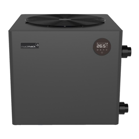
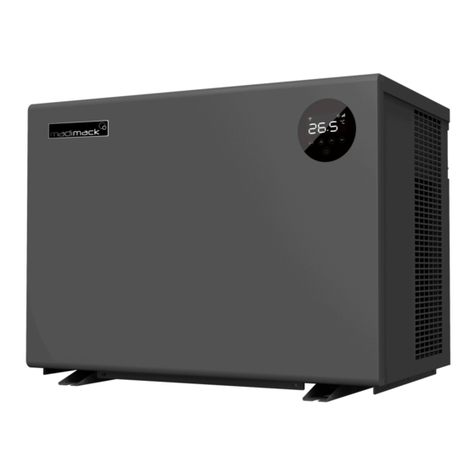
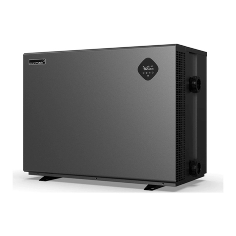
Madimack Elite Max User manual

Elite Max
COMMERCIAL POOL HEAT PUMP
User’s Manual

Table of contents
Foreword 5
A. Safety Precautions 1
1. Warning 1
2. Attention 2
3. Safety 2
B. About your heat pump 3
1. Transportation 3
2. Accessories: 3
3. Operating condition and range: 4
4. Introduction of different modes: 4
5. Technical parameter 5
6. Dimension 6
C. Installation guidance 7
1. Installation reminder 7
2. Wiring requirements 9
3. Electric wiring Diagram 11
4. Installation options 12
D. Operation guidance 16
1. Key Function 16
2. Operation Instruction 17
E. Testing 19
F. Commissioning 20
F. Maintenance 21
G. Trouble shooting for common faults 22
H. Electrical wiring schematic 25
Water Testing Pump Output 26
External input 26
I. Wi-Fi operation 27
Product Warranty Registration 36

Foreword
Thank you for choosing the Madimack high efficiency inverter pool heat pump.
All our heat pumps are built and designed to the highest standard and are protected by our extended
warranty service for peace of mind.
Warranty registration is required to be submitted online in conjunction with the commissioning page and
warranty registration page in the Appendix section at the back of the booklet
www.madimack.com.au/warranty-registration
Please read and fully understand all information provided before attempting to install the pool heat pump.
For technical questions and further information please contact
We hope you enjoy using our heat pumps.
Thank you!

A. Safety Precautions
We have provided important safety messages in this manual for the installation, maintenance and repair
of your heater.
Please read thoroughly and obey all safety messages.
1. Warning
The WARNING sign denotes a hazard. It calls attention to a procedure, practice, or the like,
which, if not correctly performed or adhered to, could result in personal injury or injury to a
third party. These signs are rare, but are extremely important.
a. Keep the heat pump away from fire source.
b. Unit must be placed in a well-ventilated area; indoor or enclosed areas are not
allowed.
c. Repair and disposal must be carried out by trained service personnel
d. Vacuum the system completely before welding.
Welding should only be carried out by professional trained personnel.

2. Attention
a. Please read the following instructions before installation, use and maintenance.
b. Installation, must be completed only by competent persons only, and in accordance with this manual.
c. Check all water connections are sealed and tested before operating the heat pump
d. Except for the methods recommended by the manufacturer, do not use any methods to accelerate
the defrosting process or clean the frosted parts.
e. If a repair is required, please contact the nearest after-sales service center. The repair process must
be strictly in accordance with this manual. Repairs made by unauthorized persons may void the
warranty.
f. Correctly set temperature required for personal preference making sure to avoid overheating or
overcooling.
g. Please do not stack substances or other materials which may block the air flows to the inlet or outlet
areas. This causes the efficiency of the heater to be reduced, and may damage the machine.
h. Do not use or stock combustible gas or liquids such as thinners, paint and fuel, to avoid fire!
i. In order to optimize the heating effect, please install heat preservation insulation on pipes between
swimming pool and the heater, and please use a recommended cover on the swimming pool.
j. Connecting pipes of the swimming pool and the heater should be less than 10m.
3. Safety
a. Please keep the main power supply out of reach from the children.
b. If power is suddenly disconnected during operation, and later the power is restored, the heater will
start up automatically.
c. Please switch off the main power supply in high storm weather to prevent the machine from damage
that could be caused by lightning strikes.
d. Any repairs should be carried out in a well-ventilated area. Any source of ignition is prohibited during
the inspection.
e. Safety inspections must be carried before the maintenance or repair for heat pumps with R32 gas in
order to minimize the risk.

B. About your heat pump
1. Transportation
a. Always keep upright
b. Loosen the screws in the bottom,
and use a forklift to transport.
c. Do not lift by the water unions, otherwise, the titanium
heat exchanger inside the heat pump may be
damaged)
2. Accessories:

3. Operating condition and range:
To pro v i de y o u c o m fo r t a n d pl e asure, please set swimming pool water temperature efficiently and
economically.
The heat pump can work between air -10°C~43°C, and its ideal operation range is between air 15°C ~
25°C.
4. Introduction of different modes:
a. The heat pump has two modes: Boost and Silent.
b. They have different strengths under different conditions.
Mode
Modes
Strength
Boost mode
Heating capacity: 20% to 100% capacity
Intelligent optimization
Fast heating
Silent mode
Heating capacity: 20% to 80% capacity
Sound level: 3dB (A) lower than Boost mode

5. Technical parameter
Model
EM60
EM110
PERFORMANCE CONDITION: Air 27°C/ Water 27°C/ Humid. 80%
Heating capacity (kW)
60.2
115.0
Average COP at 50% Speed
10.5
10
PERFORMANCE CONDITION: Air 15°C/ Water 26°C/ Humid. 70%
Heating capacity (kW)
40.1
80.8
Average COP at 50% Speed
7
7
TECHNICAL SPECIFICATIONS
Advised pool volume (m3) *
125~260
250~520
Operating air temperature (℃)
-10℃~43℃
Fan direction
Vertical
Power supply
400V/3Ph/50Hz
Rated input power (kW)
2.26~8.90
4.68~17.5
Rated input current (A)
3.27~12.9
6.78~25.3
Max input current (A)
20
40
Sound level at 10m dB(A)
33.0~41.0
35.0~44.0
Advised water flux (m³/h)
20~25
40~50
Water connection (mm)
65
100
Net dimension LxWxH (mm)
1000x1110x1260
2100x1090x1280
Net Weight (kg)
212
459
Remarks:
This heat pump is able to perform normal within air temp -10℃~43℃, efficiency will not be guaranteed out of
this range. Please take into consideration that the pool heater performance and parameters are different under
various conditions.
Related parameters are subject to adjustment periodically for technical improvement without further notice.
For details please refer to nameplate.

6. Dimension
E
B
F
G
D
A
H
C
A
B
C
D
E
F
G
H
EM60
1000
660
1110
1070
1000
780
105
1260
A
B
C
D
E
F
G
H
EM110
1000
1630
1090
1050
2100
515
140
1280
Name
Size (mm)
Model
Name
Size (mm)
Model

C. Installation guidance
1. Installation reminder
Only competent persons are authorized to install the heat pump and should be educated with the relevant
building codes and standards of their current state or local governing body for all electrical, mechanical
and water services to prevent danger or damage to the unit.
a. Location and water pipe connection
The inverter pool heat pump must be installed in a well-ventilated place.
b. Typical installation diagram
Installations can differ dependent on site conditions below is only a representation of one possibility.
Note: the inlet and outlet positions for the pipework is a representation only and can be positioned
differently

Plumbing connection installation guide
2. Placing the unit and water connections
a. Placing the unit and fixing
• The frame must be fixed by bolts (M10) to a concrete foundation or brackets. The concrete
foundation must be solid and fastened; the bracket must be strong enough and anti-rust treated.
• Do not stack substances that will block air flow near the inlet or outlet area, and there should be
no obstruction within 50cm behind the machine. Suffocation of air reduces the efficiency of the
heater and could damage the unit.
• The machine may need an additional pump (not supplied). The recommended pump must
adhere to the specification-flux of the machine, please refer to the technical parameters.
b. Water connections
• The inlet and outlet water unions should not be installed with soft flexible pipes. The heat pump
must be connected with rigid pipes!

Electrical connection installation guide
2. Wiring requirements
a. Connect the heat pump to an appropriate power supply, the voltage should comply with the rated
voltage of the product.
b. The machine must be earthed
c. Wiring must be handled by a professional technician according to the circuit diagram.
d. Install electrical protection device according to local code for wiring
e. The layout of power cable and signal cable should be orderly and not affecting each other.
Step 1. opening the maintenance panel
! Remove three screws outside
" Open the panel
# Remove two screws inside
$ Open the internal

Step 2. Power cord must be passed through below 3 holes
! Connect the wire through three holes
" Restore the internal panel
# Fix the internal panel by two screws
$ Restore the panel
% Fix the panel by three screws

3. Electric wiring Diagram
For power supply: 400V 50Hz
Note: 1) Must be hard wired, plug is not allowed.
2) The swimming pool heat pump must be earthed
Current protection devices must be installed in accordance with local electrical regulations
Please see appendix for further wiring information including pump control and auxiliary input
Distribution Box(Not provided)
Power Cord
Swimming Pool Heat Pump Wiring Board
Power Supply
400V 50Hz
Breaker
Earth
Fuse

4. Installation options
a. Flow switch activated heating
The heat pump is activated by the flow of water initiated from the filtration circulation pump, if the
heater gets to temperature within the timers the unit will first start to use the inverter technology
to slow the machine down to maintain the temperature and eventually to a stop.
1- Chlorinator controller initiates the filtration pump.
2- Heat pump’s flow switch senses the water flowing through the heat pump.
3- Heat pump starts and will run until temperature is reached or filtration pump switches off
4- No additional internal wiring to the heat pump is required in this set up
5- No additional settings needed to be changed
6- If circulation pump is not running and no flow is detected unit will display E3 – this is normal and
an indication the unit is sitting idle waiting for the filtration pump to start again.
7- If the pool temperature is not reached within the filtration times you may need to extend the timers
to match the heating requirement.

b. Heat pump activation without using the chlorinator controller and using the one
pump used for filtration (additional controller required)
An on board pump output relay can activate the main filtration pump by using it in
combination with a single pump controller without using the chlorinator timers needing to
be activated which will stop over chlorination but still use a single supply pipework for the
pool. This set-up is best when only single pipework is available from pool and doesn’t have
individual heating pipework. Efficient with only one pump working.
1- The pump output switch relay labelled P1 – P2 in the heat pump can activate the filtration pump
through the single pump controller (MJ-Box), therefore being able to run the heat pump
individually with the same pump
2- Relay switch P1 – P2 are initiated as soon as the heat pump is turned on, the output will run the
circulation pump until the heated water reaches the set temperature or is switched off by the WiFi
timers.
3- If the unit reached temperature still within the timer set points, the unit will test the water by starting
the filtration pump once an hour for 2 minutes to get an accurate temperature reading and will
start heating process again if required.
4- When Wi-Fi timers are set through the app Relay switch will run the pump output accordingly.
5- Timers for the heat pump are on the Wi-Fi app (If no WiFi available additional timer may be
required) internal setting require changing to suit this operation.
6- See electrical diagram supplied with M-box for further information.

c. Individual circulation pump installation.
An onboard output initiates the circulation pump to start and stop from the heat pump itself
based on temperature and timers. For use when there are dedicated heating pipes and to
separate from the filtration timers.
1- Termination points are labelled P1-P2 from the on board relay and is activated by the timers and
pool temperature, and will continue to run the pump until the heated water reaches the set
temperature or the timer switches off.
2- Once temperature is reached or the timer is finished the heat pump will switch off the relay output
stopping the circulation pump.
3- If the pool reaches temperature but the timer is still active the heat pump will switch off relay to stop
the circulation pump. Whilst the timer is still active every hour it will run the circulation pump for 2
minutes to test the water temperature. If the temperature is 1 degree below set point the heat pump
will continue to run the circulation pump and start the heating process again.
4- P1 – P2 relay up to 10A output for circulation pump (check total load on circuit when combined)
(P1 and P2 is an output relay switch not active neutral terminals, please see wiring diagram for
further information.
5- Heat Pump timers are set through the mobile application and required a WiFi connection. If no WiFi
is present then additional external timer may be required (sold separately)
6- It is recommended to install a power point for the pump to plug into for any future service work to
the pump which may be required.
7- Circulation pump should be sized accordingly to suit the site conditions and flow required.

d. Solar retro
In some situations, when a heat pump is replacing a solar heating system, the pipework is
available to be used next to the house but there is no way of adding a new electrical circuit
to the pool equipment. With the use of an additional temperature sensor you can use the in-
built flow switch to activate the heating. Allowing you to use the existing solar pump and to
install the heater closer to the switch board.
1- In may be impractical to get a new power cable from the house switch board to the pool equipment
area due to finished flooring etc, in this case It may be possible to use the existing pipework which
connects to the house and install a power cable from there.
2- An external thermostat controller can initiate the existing circulation pump, thus running the heat
pump through the flow switch for full temperature control.
Please speak to you installer for more information.
3- No additional wiring to the heat pump is needed internally
4- Timers are set on the external thermostatic controller
5- Set heat pump a couple of degrees above the set point temperature of the external temperature
controller.
e. Automation system
The heat pump comes with easy to connect terminals in the electrical compartment labelled as 5 and
6. The unit comes prewired with a bridge cable connected. To add an external control to active the
heat pump remove the bridge and add in a volt free terminal connection. Please check with the
automation system provider that the connection is volt free and the best way to install with their set-
up.

D. Operation guidance
1. Key Function
Symbol
Heating & cooling models
i. Power On/Off
ii. Wi-Fi setting
i. Lock/Unlock Screen
ii. Heating mode (18-40°C)
iii. Cooling mode (12-30°C)
iv. Auto mode (12-40°C)
i. Boost
ii. Silence
Temp e r at u re Se t t in g
a. Standby mode or Screen lock:Only symbol lights up, screen and other buttons turn darker.
b. Power off mode: Only symbol will light up,No display on screen.
c. The controller has a power-saving mode and will not display bright when locked.
d. The controller has a built-in memory so all parameters are saved in the event of power loss

2. Operation Instruction
a. Screen Lock
1) Press for 3 seconds to lock or unlock the screen
2) Automatic Lock Period: 30 seconds if no operation
b. Power On
Press for 3 seconds to unlock screen, Press to power on machine.
c. Temperature Setting
Press and to display and adjust set temperature.
d. Mode Selection
Heating/Cooling/Auto
Press to switch between heating , cooling and auto mode ”
Heating mode : Water temperature setting range(18-40°C)
Cooling mode : Water temperature setting range(12~30°C)
Auto mode : Water temperature setting range(12~40°C)
* When water inlet temperature is higher than setting point, automatic cooling mode starts.
* When water inlet temperature is lower than setting point, automatic heating mode starts.
Silence/Boost mode selection
Press to switch among boost mode , silence mode
Default mode: boost
Please choose boost mode for initial heating
e. WIFI
When the screen is on, press for 3 seconds, after flashing, enter Wi-Fi connection.
Connect Wi-Fi on mobile phone and input password, and then control equipment by Wi-Fi. When
APP connects Wi-Fi successfully, lights on
PLEASE SEE WiFi OPERATION GUIDE FOR FURTHER INFORMATION
Other manuals for Elite Max
1
This manual suits for next models
2
Table of contents
Other Madimack Heat Pump manuals
Popular Heat Pump manuals by other brands

STIEBEL ELTRON
STIEBEL ELTRON WPL 15 AS Operation and installation

Oilon
Oilon RE 110 Installation and operation manual

Pioneer
Pioneer YH024GHFI18RT2 Technical & service manual

Bard
Bard WH241D installation instructions

elco
elco AQUATOP T Series Planning Document

Daikin
Daikin LFSLHS0200AXV1 OPERATING AND INSTALLATION Manual

Bitzer
Bitzer ECOSTAR LHV6/2DC-3.F1Y operating instructions

DeDietrich
DeDietrich HPI S user guide

Panasonic
Panasonic WH-MXC12G9E8 operating instructions

Bard
Bard Q-TEC QH Series installation instructions

Dimplex
Dimplex LIH 10TE Installation and operating instructions

Panasonic
Panasonic Secon WH-MXC16J9E8 Service manual