Pentair Pool Products AquaLuminator User manual


Rev. G 4-23-121 P/N 619339
AquaLuminator® Light and Return Water Flow for
Above Ground Pools Owner's Manual
Important Notice
Attention Installer.
This manual contains important information about the installation, operation
and safe use of this product. This information should be given to the owner/
operator of this equipment.
WARNING
Before installing this product, read and follow all warning notices and instructions
accompanying this light. Failure to follow safety warnings and instructions can result in
severe injury, death, or property damage. Call (800) 831-7133 for additional free copies of
these instructions.
Table of Contents
SECTION I. IMPORTANT SAFETY INSTRUCTIONS......................................................... 2
SECTION II. LAMP HOUSING INSTALLATION .................................................................. 2
SECTION III. ELECTRICAL CONNECTIONS FOR STORABLE POOLS ............................ 5
SECTION IV. RELAMPING INSTRUCTIONS ........................................................................ 6
SECTION V. STORAGE AND WINTERIZING INSTRUCTIONS ........................................ 7
SECTION VI. REPLACEMENT PARTS. .................................................................................. 8
IMPORTANT SAFETY INSTRUCTIONS
READ AND FOLLOW ALL INSTRUCTIONS
SAVE THESE INSTRUCTIONS
Pentair Water Pool and Spa, Inc.
1620 Hawkins Ave., Sanford, NC 27330 • (800) 831-7133 • (919) 566-8000
10951 West Los Angeles Ave., Moorpark, CA 93021 • (800) 831-7133 • (805) 553-5000
Visit us on the Internet at: www.pentairpool.com or www.staritepool.com

P/N 619339 2 REV. G 4-23-12
SECTION I. IMPORTANT SAFETY INSTRUCTIONS
When installing and using this electrical equipment, basic safety precautions should always be followed,
including the following.
1. This light can be installed on storable above ground or permanent above ground pools.
2. To reduce the risk of electric shock, if any cord becomes damaged, return the entire transformer
assembly for repair or replacement.
3. Risk of entrapment, injury or death. Use plumbing passageways only to return water to pool. Do not use
as a suction device.
4. Risk of electrical shock. Connect only to a grounding type circuit protected by a ground fault circuit
interrupter. Contact a licensed electrician if you cannot verify that the receptacle or circuit is protected
by a ground fault circuit interrupter. Do not use an extension cord.
5. Locate your pool so that the wall is at least 3.0 meters from all electrical receptacles and at least 6.1
meters from all receptacles not protected by a ground fault circuit interrupter. It is also very important
to locate the pool so that it is not under any electrical wiring, that is less than 5.5 meters vertically
above the pool wall and within an area located 3.0 meters outside the pool walls. The pool must also
never be located under any lighting fixture or within 1.7 meters measured horizontally from any fixture
mounted less than 1.7 meters vertically above the pool water level.
6. Risk of injury. Install the top of the lens with a minimum of 20.3 centimeters and a maximum of 25.4
centimeters below top of pool wall or in manufacturers pre-punched return fitting hole.
7. Do not use electrical equipment within 3.0 meters of pool wall unless specifically C.E. listed for that use.
SECTION II. LAMP HOUSING INSTALLATION
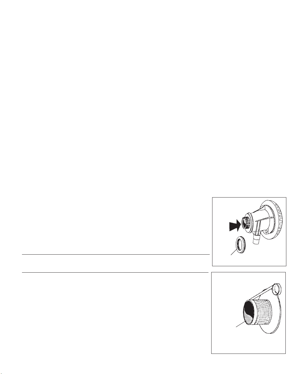
1. Remove the bulb retainer nut and push the bulb assembly out from the rear
of the fitting body so that it will come out of the front of the fitting. The
flow director will come off along with the bulb assembly; see Figure 1.
Push the red cap/plug in the end of the bulb assembly. It will be removed
later.
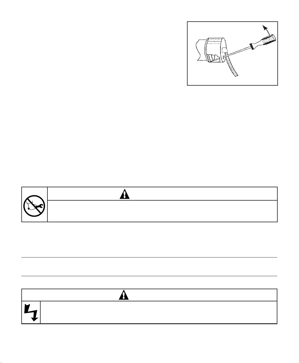
2. Unscrew the threaded wall flange from the fitting body by rotating it
counter-clockwise.
NOTE
Retain the gaskets supplied and keep them accessible.
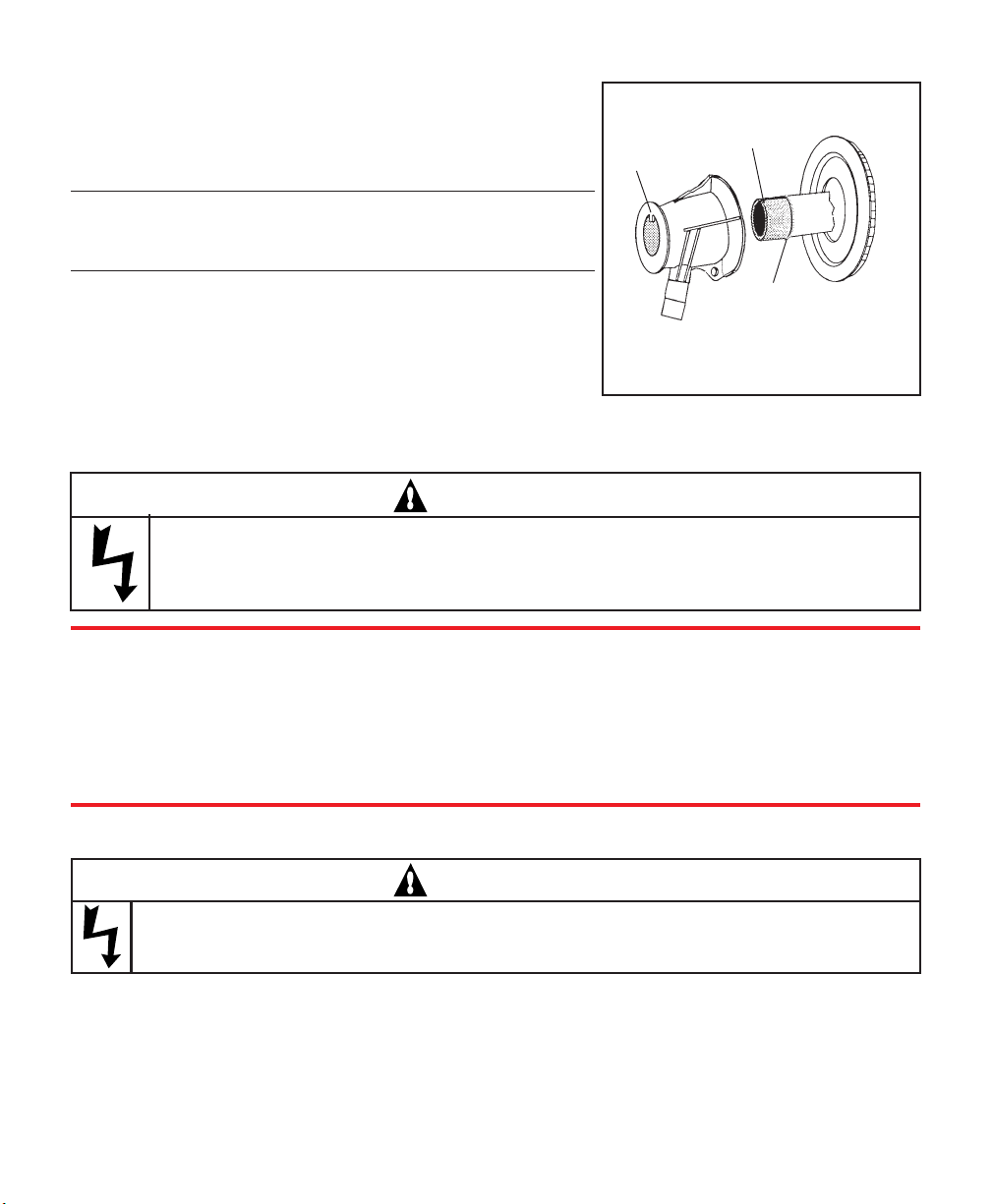
3. Use the thread seal tape provided. Snugly wrap the threaded wall
flange in a clockwise direction (as viewed from the back) starting at the
edge of the threads; see Figure 2. Work towards the flange lip
(overlapping 1/2 of the tape width with each wrap) then back towards
the starting point.
• If you have a new pool, move on to step 10.
• If the water level is below the return fitting on an existing pool,
remove the old fitting and move on to step 10.
• If the pool is full of water, follow steps 5 through 9. Figure 2.
Start at the
edge
Alwayswrap thread seal
tapeclockwise
Figure 1.
P
U
S
H
Bulb Retainer Nut

Rev. G 4-23-123 P/N 619339
NOTE
Steps 4 through 8 require two (2) No. 9 winterizing plugs (not supplied).
4. Remove the existing eyeball fitting from the return fitting on your pool
wall, see Figure 3.
5. Place a winterizing plug in the front side of the existing return fitting and
disconnect the return hose and clamp from the existing fitting.
6. Place a winterizing plug in the front side of the AquaLuminator threaded
wall flange.
7. Whileholding the existingreturn fitting fromthe inside ofthe pool, remove
the large nut or the existing fitting body on the outside of the pool wall.
8. Using a folded rag in the palm of your hand, push the old return fitting
outof the wall from theoutside of thepool; see Figure 4. Holdthe rag firmly
against the wall to prevent water spillage.
9. Insert the flange and gasket from the inside of the pool through the hole
cut out for the inlet fitting. Ensure that the threaded wall flange is centered
on the hole.
10. Take the remaining gasket and put it on the threaded wall flange from the
outside of the pool; see Figure 5. Standard sheet metal walls will have one
gasket and one spacer left over. Do not use these two items, as they are
for use on narrow interlocking wall panels only.
CAUTION
For narrow, interlocking, extruded aluminum wall panels, center flange between the ridges while
viewed from the inside of the pool. Add the spacer and additional gasket to the flange before inserting
the flange through the wall panel. This is necessary to accommodate a fountain attachment.
WARNING
The light fixture must be mounted so that the word "top" is at the top of the fixture when installed.
Incorrect orientation and a low water condition can damage the light fixture.
Liner
Existing
Eyeball
Return Fitting
Nut
Pool wall
Hose
Use a folded rag in the palm of your
hand to hold the water in the pool
while changing fittings.
Figure 3.
Figure 4.
O-Ring—Use silicone lubricant only.
Do not use any petroleum lubricants.
Bulb Assy.
Flow Director
Flange
Liner
Pool Wall
Body
Nut
(Bulb Assy.)
Gasket
Gasket
Red Cap/Plug. Remove after bulb is in
place in the Fitting Body.
Figure 5.

P/N 619339 4 REV. G 4-23-12
11. With the inlet port of the fitting body in the 3 O’clock position, place the fitting body against the
threads of the flange and keeping the inlet port in the 3 O’clock position; see Figure 6. Hand tighten the
flange as tight as possible. Rotate the flange, not the body.
CAUTION
Do not over tighten the flange.
12. To complete the tightening process, hold the flange in place
and rotate the fitting body until the inlet port is in the 6
o’clock position; see Figure 6.
13. Take a hose clamp and place it over the return hose cuff.
14. Slip the return hose from the equipment, over the inlet port,
and tighten the hose clamp securely; see Figure 7.
15. Take the bulb assembly and insert it through the flow
director. Note the aligning keyway on the bulb assembly as
shown in Figure 8. The keyway must point in the same
direction as the top key on the fitting body.
16. Now, from inside the pool, push the bulb assembly and flow director with the red cap/plug in place into
the fitting body until the bulb assembly/flow director are nearly flush against the inside pool wall.
17. Thread the bulb assembly nut until it just touches the fitting body, then finger tighten.
CAUTION
Do not over tighten as adjustability of the flow director may be impaired and/or damage to parts
causing leakage may occur. If the flow director does not rotate by hand, the nut is too tight.
18. Take the red cap/plug off and gently bring the wire connectors through the back side of the bulb
assembly. Save the red cap/plug for storage and winterizing.
CAUTION
This lighting fixture may be damaged if subjected to
freezing weather. See winterizing instructions for details
on how to store the bulb assembly.
Inlet Port 3
O’clock
position
Body
Pool Wall Wall
Flange
Liner
Gaskets (2)
Hose
Clamp
Figure 7.
6 O’clockFigure 6.

Rev. G 4-23-125 P/N 619339
SECTION III. ELECTRICALCONNECTIONS
FOR STORABLE POOLS
1. Connect the wire connectors from the bulb assembly to the
wire connectors attached to the snap-on cord cap.
NOTE
There is no polarity (no positive or negative) to the wires, either
connection will work.
2. Snap the cap onto the end of the body and turn so that the
electrical cord is pointing down.
3. Mount the transformer on the vertical wall using the single
screw provided.
4. Plug the power cord’s 2-prong plug into an appropriate 220V
ground fault circuit interrupter protected receptacle at least 3.0 meters from the pool.
5. If the light is not on, press the switch on the transformer case once.
WARNING
Risk of electric shock. Connect only to a grounding-type receptacle protected by a ground
fault circuit interrupter. Do not use extension cords for connection. Failure to do so can
result in death or severe personal injury.
øøøWHAT IS A ground fault circuit interrupter???
A ëGround Fault Circuit Interrupterí is an electrical safety device designed to measure electri-
cal leakage in a circuit. It is far more sensitive than a standard circuit breaker. Ground fault
circuit interrupter equipped breakers and outlet combinations react to unsafe leakage and shut
the power off before electrical shock injury can occur. Any electrical device used within 3.0
meters of a pool must be protected by a ground fault circuit interrupter equipped outlet or a
ground fault circuit interrupter equipped circuit breaker and be intended for such use.
SECTION IV. RELAMPING INSTRUCTIONS
WARNING
Risk of electric shock. Disconnect power before servicing this unit. Failure to disconnect
power can result in death or severe personal injury.
1. It is desirable to reduce the water level to the lower edge of the flow director. This makes bulb assembly
replacement easier, but it is not mandatory.
2. Remove power from the unit by taking the power cord’s 2-prong plug and disconnecting it from its
electrical outlet, or in the case of a hard-wired application, by turning the respective circuit breaker to
the OFF position.
O-Ring—use silicone lubricant
only. Do not use any
petroleum products.
Key Keyway
Figure 8.

P/N 619339 6 REV. G 4-23-12
3. Remove the snap-on cord cap by inserting a slotted screw
driver into the access hole as illustrated in Figure 9 and prying
upwards.
4. Disconnect both wire connectors and put the snap-on cord cap
aside in a dry location and remove the bulb assembly nut.
5. At this point you should have the new replacement bulb
assembly accessible and confirm that the red cap/plug is pressed
firmly into the bulb assembly to prevent water from entering the
bulb assembly.
6. If you were able to lower the water level as suggested in step 1, then simply remove the old bulb assembly
by pulling on the flow director while pushing the bulb assembly from the outside of the pool. If you were
unable to lower the water level, follow these instructions: push the bulb assembly out from the outside of
the pool, keeping the back of the fitting covered with a folded rag in the palm of your hand to prevent water
loss from the rear of the fitting body. Pull the flow director and bulb.
7. Take the new replacement bulb assembly with the red cap/plug in place and insert the bulb assembly
through the flow director. Note the aligning keyway on the bulb assembly as shown in Figure 8. The
keyway must point in the same direction as the top key on the fitting body.
Now, from inside the pool, push the bulb assembly with the flow director into the fitting body until
both are nearly flush against the inside pool wall. You can now remove your hand and the fitting should
again be sealed.
8. Thread the bulb assembly nut until it just touches the fitting body, then finger tighten.
CAUTION
Do not over tighten as adjustability of flow director may be impaired and/or damage to parts
causing leakage may occur. If low director does not rotate by hand, nut is too tight.
9. Take the red cap/plug off and gently bring the wire connectors through the back side of the bulb
assembly. Save red cap/plug for storage and winterizing.
10. Connect the wire connectors from the bulb assembly to the wire connectors attached to the snap-on
cord cap.
NOTE
There is no polarity (no positive or negative) to the wires, either connection will work.
11. Snap cap onto end of body and turn so that the electrical cord is pointing down.
WARNING
Risk of electric shock. Connect only to a circuit protected by a ground fault circuit
interrupter. Failure to do so can result in death and/or serious injury.
Figure 9.

Rev. G 4-23-127 P/N 619339
12. Reconnect the power to a circuit in accordance with the appropriate electrical connections. See Section
III, Electrical Connections. If the light is not on, press the switch on the transformer case once.
WARNING
This is an electrical appliance. Unsupervised use of this product by children can result in injury
and/ordeath.
SECTION V. STORAGE AND WINTERIZING INSTRUCTIONS
1. It is common practice to drain the water level to a point below the skimmer and the light, for winterizing.
2. For storable pools: remove power from the unit by taking the power cords’ three-prong plug and
disconnecting it from its electrical outlet.
3. Remove the snap-on cord cap by inserting a slotted screwdriver into the access hole and prying
upwards, as illustrated in Figure 9, Section IV Relamping Instructions.
4. The wire connectors should be gently disconnected and pushed into the rear of the bulb assembly.
5. Push red cap/plug into rear of bulb assembly to seal it.
6. Remove the bulb assembly nut.
7. Remove the bulb assembly by pulling on the flow director while pushing the bulb assembly from the
outside of the pool.
NOTE
The fitting body, threaded wall flange and gaskets may remain attached to the pool wall when winterizing, but
should be removed if pool is to be stored.
8. For storable pools: remove the transformer from its mounting by lifting up and out.
9. Place all the parts together in a box and store indoors.
When reinstalling bulb assembly next season do not use petroleum base product.
CAUTION
Do not use any petroleum base lubricant. Petroleum base products will destroy plastic parts.
Lubricate o-ring with a silicone lubricant only. A new o-ring should be used each time the bulb
assembly is removed.

P/N 619339 8 REV. G 4-23-12
8
10
58
VINYL
LINER POOL
WALL
10
Extra Gasket and
Spacer for Narrow
Interlocking Wall Panels.
This is necessary to
accommodate the
Fountain Attachment.
SECTION VI. TECHNICAL DATA
A. REPLACEMENTPARTS.
1. 79123401 Lens,ëLuxuryí,blue
1. 49300000 Lens,ëLuxuryí,red
2. 69100000 BulbAssembly
3. 79116900 O-ring
4. 79102800 Flow Director
5. 79118300 Wall Flange, Threaded
6. 79126900 FittingBody
7. 79116600 Nut
8. 79116800 Gasket (2)
9. 83000000 Trans./J-BoxAssy. w/snap-oncord cap
10. 79110700 Spacer,Mounting
SAVE THESE INSTRUCTIONS
© 2012 Pentair Water Pool and Spa, Inc. All rights reserved.
This document is subject to change without notice.
Trademarks and Disclaimers: AquaLuminator®and Pentair Water Pool and Spa®are
trademarks and/or registered trademarks of Pentair Water
Pool and Spa Inc. and/or its affiliated companies in the United States and/or other counties. Unless noted, names and brands of others that may
be used in this document are not used to indicate an affiliation or endorsement between the proprietors of these names and brands and Pentair
Water Pool and Spa, Inc. Those names and brands may be the trademarks or registered trademarks of those parties or others.
Pentair Water Pool and Spa, Inc.
1620 Hawkins Ave., Sanford, NC 27330 • (800) 831-7133 • (919) 566-8000
10951 West Los Angeles Ave., Moorpark, CA 93021 • (800) 831-7133 • (805) 553-5000
Visit us on the Internet at: www.pentairpool.com or www.staritepool.com

Tel. 5 537 9147 y 556 413 0072
Gardenias 1, Santa María Palapa, San Martín de las
Pirámides, Edo. Méx. CP. 55851
www.quimiapool.com
Table of contents
Other Pentair Pool Products Swimming Pool Lighting manuals

Pentair Pool Products
Pentair Pool Products Pool and Spa MagicStream Laminar User manual

Pentair Pool Products
Pentair Pool Products IntelliBrite 5G 560001 User manual

Pentair Pool Products
Pentair Pool Products FIBERworks 20100100 User manual

Pentair Pool Products
Pentair Pool Products SpaBrite Reference guide
Popular Swimming Pool Lighting manuals by other brands

Fiberli
Fiberli AC5G installation guide

iGuzzini
iGuzzini BH81 Instructions for use

Waterco
Waterco Rainbow BRITESTREAM SLI90 owner's manual

BWT
BWT PL-06 Installation and operating instructions

Halco
Halco ProLED FLCN Installation and operation guide

J&J Electronics
J&J Electronics PureWhite 2 Installation and operation guide