Pentair Pool Products PB4RO-75 User manual

PB4RO-75 Specifications
Your Water
Pressure Range: 40–100 psi
(2.8–6.9 bar)
Temperature Range: 40–100°F
(4.4-37.8°C)
Total Dissolved Solids < 2000 ppm
Maximum Hardness* †:10 gpg
(171 mg/L)
Sulfide, Iron and Manganese †:
< 0.1
Chlorine in Water Supply: < 2 ppm
Water Supply pH Limits:
3-11
Turbidity: 5 NTU Max.
Date of Purchase:
• Hand or Elect
ric
Drill •
P
• 2 Adjustable Wrenches • D
• File •
T
• Pencil
•
S
• Needle-nose
Pliers
•
T
• Utility Knife or Tube Cutter
• Hand or Electric
D
rill •
C
• Drill Bits: 1/4" and
3/4" •
R
• Teflon
®
Tape
• 1
• Head Assembly •
D
• Screws for mounti
ng •
• Lead-free air gap
water faucet
drinking • Q
• Silicone grease
•
S
• Tank Valve •
F
• Teflon
®
Tape
• C
• 3/8" Plastic Tubing •
1
(red and blue) (
• TDS Test Kit
• Filter Cartridges:
Model PB4RO-75 Undersink Reverse Osmosis System
User Manual
OPERATINGSPECIFICATIONS
WARNING: Beforeinstallingthesystem,makecertain
your water supply complies with the
following operating specifications. Failure
to do so may reduce the effectiveness
of the system and will void the warranty.
Consult your local water treatment utility
or a certified water testing lab to determine
the quality for your water and use the table
below to record your results for future
reference.
Tools Required
(for plastic tubing)
Optional Materials
hillips Screwdrivers
rill Bits: 1/8", 1/4" and 3/8"
owel
afety Glasses
ape Measure
(For sinks without extra hole for faucet)
enter punch
espirator
-3/8" Bi-metal or Carbide
Tipped Hole-saw
NOTE: All tools listed will not be necessary for installation.
Read installation procedures before starting to
determine required tools.
Parts Included
* If the hardness of your water is above 10 gpg (171 mg/L), lime scale will build
up rapidly on the membrane inside of the RO membrane cartridge. Scale
buildup will plug the RO membrane cartridge and make the system ineffective.
We do not recommend the PB4RO to be used with water in excess of 10 gpg
(171 mg/L) hardness, unless the water is softened prior to the reverse
osmosis
system.
† See your local dealer or water treatment specialist to reduce these substances
in your water.
PB4RO-75 Dimensions:
System Dimensions 13" H x 15" W x 4.75" Dia
(330 x 381 x 120.6 mm)
Tank Dimensions 14.5" H x 11" Dia
(368 x 279 mm)
System Weight 23 lbs (10.4 kg)
Tank Capacity 3.2 gal (12.1 L)
PW-S2500R Cartridge Yellow
PW-C5000R Cartridge Blue
PW-RO75R Cartridge Green
PW-C2500R Cartridge Violet
rain Saddle Valve
Water Supply Adapter
uick-connect Fitting
torage Tank
aucet Adapter
hange Indication Sticker
/4" Plastic Tubing
white, red and green)
247146 Rev D JA12

GENERAL PRECAUTIONS
WARNING: Donotusewithwaterthat is
microbiologically unsafe or of unknown
quality without adequate disinfection before
or after the system. Systems certified for
cyst reduction may be used on disinfected
waters that may contain filterable cysts.
WARNING: ThePB4RO containsareplaceableRO
membrane cartridge that is critical to the
efficiency of the system. Replacement of the
RO membrane cartridge should be with one
of identical specifications, as defined by the
manufacturer, to assure the same efficiency
and contaminant reduction performance.
WARNING: ThePB4RO containsareplaceableRO
membrane cartridge, critical for the effective
reduction of total dissolved solids. Product
water should be tested periodically to verify
that the system is working properly.
WARNING: ThePB4RO isacceptablefortreatment
of influent concentrations of no more
than 27 mg/L nitrate and 3 mg/L nitrite in
combination measured as N and is certified
for nitrate/nitrite reduction only for water
supplies with a pressure of 40 psig (280 kPa)
or greater.
WARNING: ThePB4RO shall only beusedfor arsenic
reduction on chlorinated water supplies
containing detectable residual free chlorine
at the system inlet. Water systems using an
in-line chlorinator should provide a one-
minute chlorine contact time before the unit.
WARNING: ThePB4RO will not protect against disease-
causing bacteria or remove naturally-
occurring harmless bacteria.
CAUTION
ThePB4ROmust be protectedagainstfreezing
which can cause the filter housing to crack,
resulting in water leakage.
CAUTION
Turn off water supply to head without cartridge if
it must be left unattended for an extended period
of time.
CAUTION
Do not use electrical heating tape on this unit.
NOTE: Substances listed as reduced are not necessarily
in your water. System must be maintained
according tomanufacturer's instructions, including
replacement of filter cartridges.
NOTE: Your water must be within required limits for
satisfactory operation. If not, the RO membrane
cartridge’s life may be shortened and your warranty
will be voided (see Operating Specifications).
NOTE: Install on cold water line only.
NOTE: Do not install where system will be exposed to
direct sunlight.
NOTE: Make certain that installation complies with all state
and local laws and regulations.
NOTE: The filter cartridges and RO membrane cartridge
included with the system have limited service lives.
Changes in taste, odor, and color of the filtered
water indicate that the cartridges and/or membrane
should be replaced.
NOTE: During extended periods of non-use (such as
during a vacation), remove the membrane cartridge
and the filter cartridges from the unit and place
them in a sealed plastic bag. Store the cartridges
in the refrigerator for future use. When re-starting
the unit, replace all cartridges and flush per
instructions.
NOTE: If the PB4RO stands for more than 2 to 3 days
without being used, the storage tank should be
emptied.
NOTE: Use only Teflon® tape without adhesive backing
to seal joints. Do not use pipe compound (“pipe
dope”), sticks, or similar compounds with this
unit; they contain petroleum derivatives which can
cause crazing and cracking of the plastic in the
filter housing.
NOTE: Use only soap and water to clean components.
NOTE: Do not use aerosol sprays (bug spray, cleaning
fluids, etc.) near the PB4RO. They contain organic
solvents which will cause crazing and cracking of
the plastic in the filter housing.
NOTE: After prolonged periods of non-use, such as a
vacation, it is recommended that the system be
flushed thoroughly. Let water run for 2 to 3 minutes
before using.
NOTE: Do not use a torch near the unit.
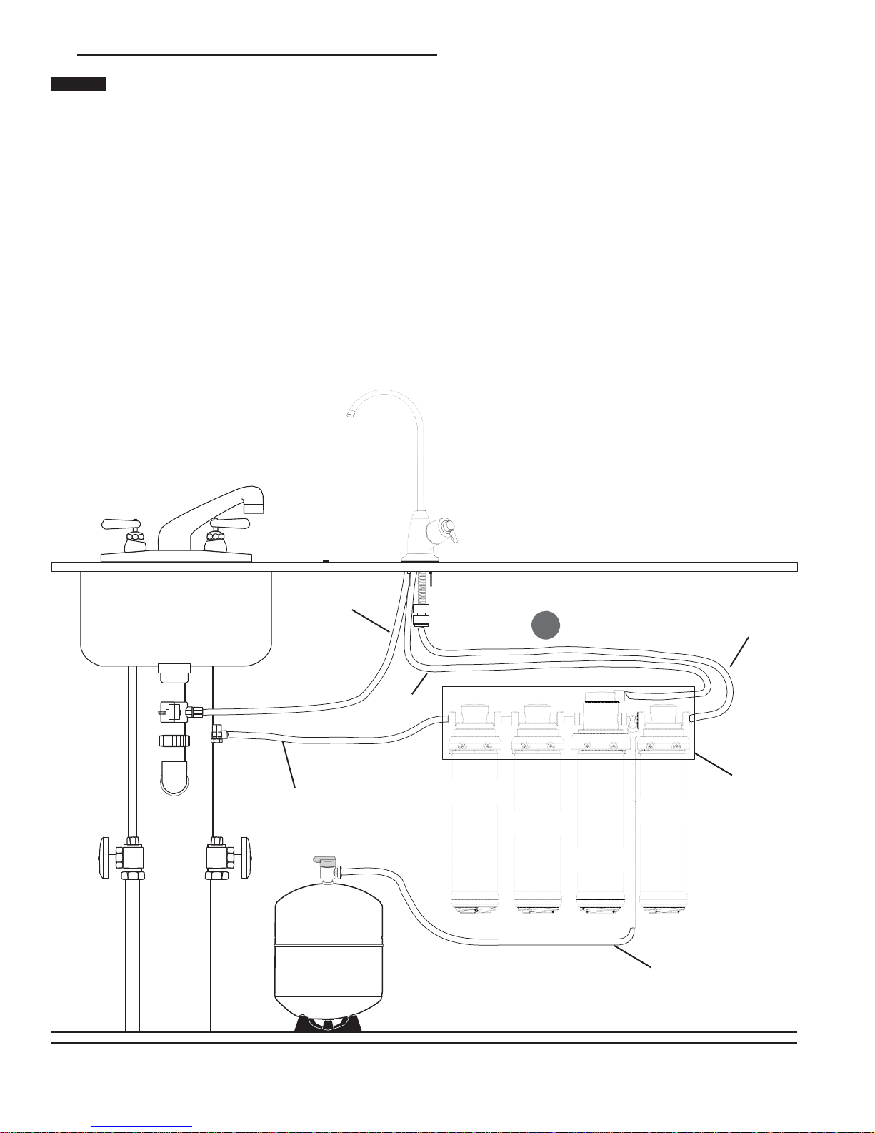
HOW REVERSE OSMOSIS (RO) WORKS
The PB4RO uses a semi-permeable membrane to reduce
dissolved salts, improving the taste and odor of your water. The
RO membrane cartridge contains multiple layers of micron-thin
film wound around a hollow center core. Water molecules can
pass through the cartridge, while dissolved salts are rejected.
Your household water supply is pre-filtered to reduce dirt and
chlorine that may foul the membrane. The RO membrane
cartridge separates this pre-filtered water into PRODUCT
WATER and REJECT WATER. Your household water pressure
forces water through the membrane within the RO membrane
cartridge, and into the storage tank. This is product water.
Dissolved salts cannot pass through the membrane and are
sent to the drain as reject water. When you open the faucet,
product water (permeate) is drawn from the storage tank
through a post-polishing filter. The post-polishing filter takes out
any remaining taste or odor in the water and provides you and
your family with cleaner, great-tasting water.
The PB4RO also features an auto shut-off valve, which shuts
off the system once the pressure in the storage tank reaches
2/3 of the incoming water pressure (your household water
pressure). When you open the faucet to draw water from
the storage tank, the pressure inside the tank drops and
the auto shut-off valve opens. The system then begins to
operate, replenishing the water you took from the storage tank.
Depending on the system's efficiency, for each gallon of water
produced, up to 7 gallons are discharged as reject water. The
storage tank can hold up to 3.2 gallons (12.1 L) of water at a
time, more than enough for the average family’s drinking and
cooking needs.
NOTE: When used under operating conditions specified
on page 1 of this manual, the RO membrane
cartridge of the PB4RO should last 12–24 months.
The precise life span of the PB4RO's RO membrane
cartridge will depend on the quality of the water
entering the system, and the frequency with which
you use it. Frequent use prevents the dissolved
salts from building up on the membrane as scale.
The more water the system is required to produce,
the longer the membrane will last. You may wish
to find a variety of uses for your PB4RO system in
order to prolong the life of the membrane.
2 • JA12 Model PB4RO-75 Undersink Reverse Osmosis System

1
D
INSTALLATION
NOTE: Please read all instructions, specifications, and
precautions before installing and using your
PB4RO system.
NOTE: The PB4RO may be installed under a sink or in the
basement.
NOTE: The PB4RO is installed vertically.
NOTE: Numbered diagrams correspond with numbered
steps.
NOTE: For standard installation on 1/2" 14 NPS threads
(most common thread on kitchen faucets) cold
water line.
1. Installing the Water SupplyAdapter
The supply adapter fits 1/2" 14 NPS supply threads. If local
codes permit, it may be used to connect the filter system
to the cold water supply line. If local codes do not permit
the use of the supply adapter, alternate connectors can be
obtained from your local retailer.
A.
Turn off cold water supply line. If cold water line does
not have a shut-off valve under the sink, one should be
installed.
B.
Turn on the cold water faucet and allow all water to
drain from line.
C.
Disconnect cold water line from 1/2" 14 NPS
threaded stub on bottom of main faucet.
D.
Screw the water supply adapter to the threaded faucet
stub as shown.
E.
Using the nut that previously connected the cold water
line to the faucet, screw the cold water line to the male
supply adapter threads.
2. Selecting the Faucet Location
NOTE: The drinking water faucet should be positioned
with function, convenience, and appearance in
mind. An adequate flat area is required to allow
faucet base to rest securely. The faucet fits through
a 1-3/8" hole. Most sinks have pre-drilled 1-3/8" or
1-1⁄2" diameter holes that may be used for faucet
installation. If these pre-drilled holes cannot be
used or are in an inconvenient location, it will
be necessary to drill a 1-3/8" hole in the sink to
accommodate the faucet.
WARNING: Thisproceduremaygeneratedustwhich
can cause severe irritation if inhaled or come
in contact with the eyes. The use of safety
glasses and respirator for this procedure is
recommended.
WARNING: Donotattempt to drill throughanall-
porcelain sink. If you have an all-porcelain
sink, mount the faucet in pre-drilled sprayer
hole or drill through countertop next to sink.
WARNING: Whendrillingthroughacountertop,make
sure the area below the drilled area is free
of wiring and piping. Make certain that
you have ample room to make the proper
connections to the bottom of the faucet.
WARNING: Donotdrill throughacountertopthatis
more than 1" thick.
WARNING: Donotattempt todrillthroughatiled,
marble, granite or similar countertop.
Consult a plumber or the countertop
manufacturer for advice or assistance.
A.
Line bottom of sink with newspaper to prevent
metal shavings, parts, or tools from falling down
drain.
E B B. Place masking tape over the area to be drilled to help
prevent scratches if drill bit slips.
C pilot hole.
D. Using a 1-3/8" hole saw, drill a hole completely through
the sink. Smooth the rough edges with a file.
F
A
Figure 1
C
C
D
⁄
4”
B
1
1
⁄
4”
A
Figure 2
Model PB4RO-75 Undersink Reverse Osmosis System JA12 • 3

INSTALLATION continued
3. Mounting the Faucet
A.
Pre-assemble the base. The rubber washer should be B
in place below the base. The two toggle bolts should be
inserted through the base and the rubber washer. The
bolts are screwed into the spring-loaded toggle.
B.
Place the base assembly over the hole in the sink. The
two toggles should pass through the hole far enough to
spring fully open. If they are not open, unscrew the bolt
until the toggle moves down to clear the sink.
C.
Look down through the base for this step. Before
Base
O-ring Seat
Black Rubber
Washer
tightening the bolts, determine the correct rotation of the
base. The final position of the handle will be 45 degrees
off from the bolt heads. Use Figure 5 to help determine
the best position for your installation.
Through the hole in the base, hold the toggle in position
while tightening the bolt. The spring loaded toggle
will contact the bottom of the counter top and hold in
position. Do not fully tighten. Repeat for second toggle
bolt.
Check the final position of the base and toggle bolts.
Tighten the two bolts evenly. DO NOT OVERTIGHTEN.
Tighten only far enough to prevent the base from
rotating when the faucet is rotated in place.
D.
Attach large diameter 3/8" (red) drain tube to the larger
barb fitting at the faucet bottom. This tube should be
long enough to reach the drain clamp in Step 7.
Will Spring Open
C
Notch For Faucet
Figure 4
45°
Notch For Faucet
Blades Must Be Held
When Tightening
E.
Locate the 1/4" red brine tube from the right side of the
system head assembly. Route the tube through the
faucet base and connect to small barb on the faucet.
Make certain that the tube is not kinked or stressed
once the head assembly is mounted.
F.
Apply 3-5 wraps of Teflon tape to faucet stem. Screw
quick connector onto end of threads.
G.
Wet end of 3/8" blue tube. Push into bottom of
connector. Tug gently to be sure connection is
complete. This tube should be long enough to reach the
top right side of the RO Assembly.
H.
Check that the O-ring is in place on the faucet. Feed
the remaining 3/8" tubes through the base. Hold the
faucet in the final position and rotate backwards (to the
left) while pushing down. The faucet will drop into the
base. Push down on the faucet and rotate forward (to
the right) to lock it into final position. The O-ring will be
seated and the faucet held securely in position.
I.
Insert the spout into the top opening. Hold in position
and screw the collar onto the base.
NOTE: If the faucet handle is not in the correct
position, remove the faucet, loosen the toggle
bolts and reposition the base. Tighten the
toggle bolts. Then reinstall the faucet.
Handle Faces This Direction
Figure 5
O-ring
D
EF
G
Figure 6
A Base
Black Rubber
Washer
Folds Upward
4 • JA12 Model PB4RO-75 Undersink Reverse Osmosis System

INSTALLATION continued
Figure 3
Model PB4RO-75 Undersink Reverse Osmosis System JA12 • 5

INSTALLATION continued
4. Mounting the System
CAUTION
The filter head assembly should be mounted on
a stud or firm surface. The mounting bracket will
support the weight of the cartridges and help
prevent strain on the water lines.
A.
Select location under sink or in basement where unit
is to be mounted. The head assembly is mounted in a
vertical position.
B.
When mounting the PB4RO-75 two screws are
supplied to mount the head. Measure up from the floor
of the cabinet 14-1/2". This will provide clearance to
change the cartridges. The two screws will be 14" apart
and level. Screw the two screws into the wall. Leave a
gap between the screw head and the wall of 1/8". The
backside of the system head has two slots that will fit
over the screw heads and slide down to lock.
14 Inches
Between Holes
B
12 Inches
From Mounting
Hole to Bottom
of Cartridge
2-1/2 Inches Clearance Below Cartridges
Figure 7
6 • JA12 Model PB4RO-75 Undersink Reverse Osmosis System

INSTALLATION continued
5. Connecting the Faucet
CAUTION
Water supplytothe tee shouldhave aseparate
shut-off valve. If it does not, a separate shut-off
should be installed.
A.
Locate the 3/8" blue tubing from the faucet and place a
mark 5/8" from the end of the tubing. Moisten the end of
the tubing with water and insert into the quick-connect
fitting on the head assembly until the mark is flush with
the quick-connect fitting.
B.
Gently pull back on the tubing to ensure it is connected
properly. If the tubing comes out of fitting, cut a small
section off of the tubing and reconnect.
NOTE: Tubing may be quickly and easily removed from
the fitting if necessary. First, turn off the water
supply to the filter. Open faucet, then press in
the collet around the fitting while pulling the
tubing with your other hand.
Step 8
A 3/8" Blue
Step 5
3/8" Red
Step 9
1/4" Red
1/4" White
Step 6 PW-S2500R
Yellow
PW-C5000R
Blue
PW-C2500R
Violet
Cover Not Shown
PW-RO75R
Green
1/4" Green
Step 11
Figure 8
Model PB4RO-75 Undersink Reverse Osmosis System JA12 • 7

INSTALLATION continued
6. Connecting the Water Supply Adapter
A.
Determine the length of 1/4" white plastic tubing needed
to connect the inlet (white collet) on the left side of the
filter with the water supply adapter. Be sure to allow
enough tubing to prevent kinking and cut the tubing
squarely. Place a mark 5/8" from the end of the tubing.
B.
Wet tubing with water and insert into water supply
adapter 5/8" until mark is flush with fitting. Repeat
inserting other end of tubing into inlet of the head
assembly.
7. Installing the Drain Clamp
NOTE: If you have a single-basin sink with a disposal
unit, call Technical support at 1-800-279-9404 for
options.
NOTE: Before installing the drain clamp, check the
drainpipes under the sink for corrosion. Corroded
pipes should be replaced before continuing with
installation.
A.
Attach the drain clamp to a vertical section of the
drainpipe, about 6" above the trap. Make sure the
opening on the drain clamp is facing towards the
drinking water faucet.
B.
Using the fitting hole of the drain clamp as a guide, drill
a 1/4" hole through one side of the drainpipe.
C.
Remove the drain clamp from the drainpipe and enlarge
the hole with a 3/8" drill bit. Use a file to remove rough
edges from the drilled hole.
D.
Make sure the black rubber gasket is adhered to the
inside of the drain clamp and place the drain clamp
assembly over the drilled hole. Look through the hole
and position the clamp so that the center of the clamp
hole is slightly higher (about 1/16") than the center
of the drilled hole, see Figure 11. Tighten the clamp
securely.
E.
Screw the plastic compression nut onto the drain clamp
until hand-tight.
A
D
E
Figure 11
8. Connecting the Faucet to the Drain
NOTE: This is a gravity drain line. Any loops, kinks or
sharp bends must be eliminated before proceeding.
Failure to create a straight line to the drain may
result in reject water leaking through the air gap
in the faucet onto the counter top and below the
faucet.
A.
Align the 3/8" red tubing from the faucet with the
compression nut on the drain clamp. Create as straight
a path as possible with the tubing. Cut the tubing
squarely below the nut and remove the internal and
external burrs.
B.
Loosen the compression nut two complete turns. Insert
the tubing into the nut until it stops. Tighten with fingers,
then tighten 1 to 2 turns with a wrench.
A
B
Figure 12
6"
Figure 9
B C
Figure 10
8 • JA12 Model PB4RO-75 Undersink Reverse Osmosis System

INSTALLATION continued
on
disinfe cted
waters
that
may
W
arning:
Do
not
u se
w ith water that
is
microbiologically
unsafe
or of
©
2010
Pentair
R
e sidential
F
iltration,
Milw
aukee,
WI
,
US A
A ssem b
l
ed
i
n
Ch
i
na
B
9. Installing the Cartridges
The cartridges are identified by the color of the label and
the model number.
Cartridge #1 = PW-S2500R, Yellow
Cartridge #2 = PW-C5000R, Blue
Cartridge #3 = PW-RO75R, Green
Cartridge #4 = PW-C2500R, Violet
Install the cartridges in order. If the cartridges are installed
out of order the system will not filter correctly.
A.
Slide the cartridge into the head until it stops.
B.
Twist the cartridge 1/4 turn clockwise until it snaps into
place. Gently pull out on the cartridge to ensure the
cartridge is locked into place.
11. Putting the System Into Operation
CAUTION
Makecertainheadassemblyisfirmlyattached
to wall to prevent it from falling and possibly
becoming damaged.
NOTE: Use caution not to bend or pinch the tubing behind
the system while attaching to mounting screws.
NOTE: The post-polishing filter may contain fine black
carbon particles. These fines are harmless, but
may make the water appear gray in color. The
carbon fines are flushed from the system with the
first tank full of water.
NOTE: The PB4RO system does not produce a high
volume of water on demand as an ordinary filter
does. Water is produced at a slow, drop-by-drop
rate. The system requires about 3 hours to fill the
storage tank. As water is taken from the tank, the
system automatically starts the cycle of replacing
the water and then stops water production when
the tank is full.
2
Qui ck Change
Sed im ent
Cartridg e
CAPAC IT Y :
Repl ace ever y 12 months
TEMPER ATUR E RANGE:
40-1 00°F (4. 4 -37 . 8°C )
PRESSURE R AN G E:
30-12 5° F (2 . 4- 8.6 B a r)
For u se with
Pentair W ater
models: PB4RO-
75, PP4RO-75 and
PB5RO-75
5
Qui ck
Change
EP
Cartridg e
CAPA CIT Y :
Replace
every 1 2
months
TEMPER A TU
RE R ANGE:
40-1 00°F
(4 .4 -3 7. 8 °C)
PRESSURE
RANGE:
30-125
°
F (2.4-8.6 Bar)
For u se with
Pentair Water
models: PB4RO-
75, PP4RO-75 and
PB5RO-75
1
2
3
Figure 13
A.
Make sure cold water faucet is “off” (Figure 14).
B.
Make sure tank valve is in the open position.
C.
Slowly turn on cold water supply.
D.
Open the faucet to turn on flow. Let the faucet run/drip
for 12 hours, then close it.
E.
Allow 3 hours for the tank to fill. Continue to periodically A
check the installation for leaks. After the storage tank
is filled, open the faucet to flush the post-filter cartridge
(on the right side of the filter housing). Allow 4 to 5
minutes for all of the water to drain from the tank. Close
faucet and allow tank to fill.
CAUTION
Visuallychecktheentire system for leaks. If aleak is
10. Connecting the Storage Tank to the System
CAUTION
When tank is full, it weighs approximately 35
pounds. Provide ample support under the tank.
A.
Apply 3-5 wraps of Teflon tape to the tank threads.
B.
Thread the tank valve onto the top of the tank opening
by turning it clockwise until snug.
C.
Locate the green tubing and a mark 3/4" from the end.
Moisten one end of the green tubing with water and
insert with a twisting motion into the free port of the tank
valve until the 3/4" mark is flush with the quick-connect
fitting.
NOTE: Do not cut green tube. This line should be left at
the pre-cut length for future service.
NOTE: The pressurized storage tank has capacity of
3.2 gallons. The tank's air pressure is factory
set at 5 to 7 psi when tank is empty.
present, see TROUBLESHOOTING.
F. Repeat Step E four times.
NOTE: Initially, the water may appear cloudy. This is a
result of air trapped in the post-filter cartridge.
It is not harmful and will disappear in a matter
of minutes. It may take up to a week after
installing a new post-filter cartridge for the
trapped air to dissipate.
The system is ready for operation. You can now enjoy quality
water from the PB4RO-75.
Closed
Tank Valve
Open
Tank Valve
Figure 14
Model PB4RO-75 Undersink Reverse Osmosis System JA12 • 9


OPTIONAL INSTALLATION
CONNECTING THE PB4RO-75 TO
REFRIGERATOR ICEMAKER/WATER
DISPENSER
CAUTION
If you areconnecting thePB4RO toyour
refrigerator/icemaker with initial system
installation, wait to turn on the icemaker until
the Post- Filter Cartridge (on the right side of the
filter housing) has been flushed according to
Step 11.
CAUTION
Use plastictubingandfittings.Donot use
copper tubing or brass fittings.
NOTE: For optimum performance, it is recommended
that the distance between the PB4RO and the
refrigerator icemaker/water dispenser be no greater
than 10 feet (3 m). At distances greater than 10 feet,
the water pressure from the system may not be
adequate to deliver water to the refrigerator.
Materials Required
(available from your local hardware store)
• 3/8" x 3/8" x 3/8" (9.5 x 9.5 x 9.5 mm) compression or
quick-connect tee.
• 3/8" (9.5 mm) polyethylene tubing (maximum length of
10 feet [3 m] recommended)
• Shut-off valve
A.
Turn off icemaker and refrigerator water supply. Consult
manufacturer’s guidelines.
B.
Close tank valve (on top of storage tank).
C.
Turn off water to the system at the cold water supply.
D.
Open drinking water faucet to relieve pressure.
E.
Locate blue tubing leading to your drinking water faucet.
Cut and insert the 3/8" x 3/8" x 3/8" (9.5 x 9.5 x 9.5 mm)
compression or quick-connect tee into the blue tubing
(Figure 15). Consult manufacturer’s guidelines before
installing the tee connection.
NOTE: When cutting the blue tubing, you may
experience some water leakage.
F.
Using a length of 3/8" polyethylene tubing, connect
the icemaker/dispenser line with the free port on
the compression tee.
G.
The shut-off valve should be installed as close to this
port of the tee as possible. Shut-off valve should be
installed in the OFF position. Consult manufacturer’s
guidelines before installing the shut-off valve.
H.
Completely open cold water supply (until it comes to
a stop).
I.
Open tank valve.
J.
Turn off the drinking water faucet.
K.
Open shut-off valve at the tee connection.
L.
Turn on ice maker. Consult manufacturer’s instructions.
M.
Check for leaks and tighten connections if necessary.
Tubing to drinking
water faucet
Tubing to
refrigerator
Figure 15
Tubing from
system outlet
Model PB4RO-75 Undersink Reverse Osmosis System JA12 • 9

TESTING YOUR REVERSE OSMOSIS
SYSTEM
Total Dissolved Solids (TDS) Test
NOTE: Under NSF/ANSI Standard 58, it is highly
recommended that you (the consumer) have your
water tested at least every 6 months to verify that
your system is performing satisfactorily.
SamplingInstructions:
Sampling instructions are included with the Total Dissolved
Solids (TDS) Test Kit. If the TDS Test Kit is missing from your
unit, please call Customer Support at 1-888-837-0028 for a
replacement.
Total Dissolved
Solids Test Kit
Figure 16
WHEN TO CHANGE THE CARTRIDGES
The life of the cartridge depends on the water volume used and
the substances in the water. Normally, cartridges should be
changed at intervals of 6 months. Replace the cartridge sooner
if the water pressure at the faucet begins to drop noticeably or
if you notice changes in the taste, color, or flow of the filtered
water.
CHANGING THE CARTRIDGES
Materials Needed
• Replacement Cartridges (color coded):
PW-S2500R Cartridge Yellow
PW-C5000R Cartridge Blue
PW-RO75R Cartridge Green
PW-C2500R Cartridge Violet
The pre-filter and post-filter cartridges need to be changed
when the water pressure at the faucet begins to drop
noticeably, or if there are changes in taste, color or flow of the
filtered water. All cartridges should be changed at the same
time. The cartridges are color coded to indicate which location
they are installed into.
1. Changing the Cartridges
NOTE: Only the replacement cartridges listed can be used
with this system. Failure to use recommended
replacement cartridges will void your warranty.
A.
Place a small pan or towel under the PB4RO to
catch any water that may drip.
B.
Twist the pre-filter cartridge (on the left side of the filter
housing) counter-clockwise for a 1/4 of a turn, and pull
the cartridge out of the system. If the system has any
significant leaks, see Troubleshooting.
C.
Push the new cartridge into the head until it can go no
further.
D.
Twist the cartridge 1/4 turn clockwise until it snaps into
place.
E.
Gently pull the cartridge straight out to ensure the
cartridge is locked into place.
F.
Repeat for all other cartridges.
G.
Turn on water and check for leaks. If leaks are found,
see Troubleshooting.
NOTE: The post filter cartridge may contain carbon
fines (very fine black powder). This will be
released during your initial flushing.
H.
Flush water through filter for 5 minutes to remove
carbon fines. Check for leaks again before
leaving installation. Allow the tank to fill.
2. Flushing the RO membrane
NOTE: The PB4RO system does not produce a high
volume of water on demand as an ordinary filter
does. Water is produced at a slow, drop-by-drop
rate. The system requires about 3 hours to fill the
storage tank. As water is taken from the tank, the
system automatically starts the cycle of replacing
the water and then stops water production when
the tank is full.
A.
Make sure cold water faucet is “off” (Figure 14).
B.
Make sure tank valve is in the open position.
C.
Slowly turn on cold water supply.
D.
Open the faucet to turn on flow. Let the faucet run/drip
for 12 hours, then close it.
E.
Allow 3 hours for the tank to fill. Continue to
periodically check the installation for leaks. After the
storage tank
is filled, open the faucet to flush the post-filter cartridge
(on the right side of the filter housing). Allow 4 to 5
minutes for all of the water to drain from the tank.
Close faucet and allow tank to fill.
CAUTION
Visually check the entire system for leaks. If a leak is
present, see TROUBLESHOOTING.
10 • JA12 Model PB4RO-75 Undersink Reverse Osmosis System

F.
Repeat Step E four times.
Model PB4RO-75 Undersink Reverse Osmosis System JA12 •


TROUBLESHOOTING
Leaks on Supply Adapter Connection
1.
Turn off water supply valve and turn on drinking water
faucet to release pressure in system.
2.
Loosen leaking threaded fitting on supply adapter or
pull out leaking tubing by pressing collar surrounding
tubing while pulling the tubing with your other hand.
3.
Inspect to see if plastic tubing is scratched and supply
adapter was properly attached.
4.
If tubing is scratched, cut off 1/2" to 5/8" and reinstall.
Leaks on Faucet/Tubing Connection
1.
Turn off water supply valve and turn on drinking water
faucet to release pressure.
2.
Unscrew tubing nut at bottom of faucet. Inspect the tubing.
The insert, plastic ring and tubing should not be damaged.
3.
Check if insert is in place and tubing is cut squarely and
not scratched, cut tubing if necessary to get square smooth
end.
4.
If the tubing is smooth and square, reconnect tubing by
inserting into faucet and tightening nut. The plastic ring
should be held tight to the faucet system when the nut is
tight.
5.
Turn on water supply valve, then close faucet and check for
leaks.
NOTE: If leaks persist, or if there are other leaks on
system, turn off water supply and call Technical
Support 1-800-279-9404.
Leaks Between Cartridge and Filter Housing
1.
Turn off cold water supply to system at saddle valve. Close
tank valve. Open drinking water faucet to relieve water
pressure.
2.
Remove the cartridge, inspecting it for damage. Inspect
O-rings to make sure they are seated and clean.
3.
Insert and twist the cartridge back into the filter housing.
4.
Turn on water supply at saddle valve. Open tank valve.
Close drinking water faucet after water begins to flow. If
leaks persist, call Technical Support.
Leak Between Tank Valve and Storage Tank
1.
Turn off water supply to system at the saddle valve. Open
faucet to drain storage tank. Let faucet run for 3–5 minutes
until it drips.
2.
Remove green tubing from tank valve by pressing the
collar around the fitting while pulling the tubing with your
other hand.
3.
Unscrew the tank valve from the storage tank.
4.
Place three wraps of Teflon® tape on the threads of the
storage tank.
5.
Thread the tank valve onto the top of the tank opening
by turning it clockwise until snug.
6.
Cut off 1" of tubing. Tubing should be cut squarely. Internal
and external burrs should be removed. Place a mark on
tubing 3/4" from end of tubing.
7.
Wet the tubing and insert until the mark is flush with the
quick-connect fitting.
8.
Turn water supply on at the saddle valve and close drinking
water faucet.
9.
Allow system to pressurize for several hours and check for
leaks.
10.
Check for leaks after tank is fully pressurized (1–3 hours). If
leak persists, call Technical Support .
Leaks at Quick-Connect Fittings
CAUTION
The 1/4" red tubing connected to the top of the
fourth cartridge has a flow restrictor installed.
The system will not operate correctly if the
restrictor is removed.
1.
Close tank valve, close saddle valve, and open drinking
water faucet.
2.
Press collar around the quick-connect fitting while
pulling the tubing with your other hand.
3.
Cut off 1" of tubing. Tubing should be cut squarely. Internal
and external burs should be removed. Place a mark on
tubing 5/8" from end on 1/4" tubing or 3/4" from end on 3/8"
tubing.
4.
Wet the end and insert tubing until the mark is flush with the
quick-connect fitting.
5.
Open the saddle valve until it comes to a stop. Open the
tank valve and close drinking water faucet. If leaks persist,
call Technical Support.
Leaks from Faucet
1.
Check to make sure white tubing leading from the drinking
water faucet to the drain is as straight as possible (it is
usually necessary to cut this line during installation). Any
kinks or sags in this drain line will impede the flow of
water to the drain.
2.
Check to make sure the drain clamp and the drain hole are
properly aligned, refer to Figure 7 on page 7).
1. Check to make sure there is no foreign matter clogging the
drain line or at the drain clamp hole. If leaks persist, call
Technical Support.
No Flow or Slow Flow from the Brine (Reject) Line (Less
than 6 fl. oz. or 180 milliliters per minute)
NOTE: Before checking brine (or reject) flow, make sure
the unit is producing water by turning the valve on
the storage tank off and opening the drinking water
faucet. Water should drip from faucet.
1.
Replace the pre-filter cartridge according to the Changing
the pre-filter cartridge instructions on page 10 and recheck
the brine (or reject) flow rate.
2.
If the pre-filter cartridge is not at fault, the brine (or reject)
flow controller could be clogged. Call Technical Support.
High TDS in Product Water
1.
If high TDS (Total Dissolved Solids) is detected in the
product water, the RO Cartridge may need to be replaced
or the reject flow control tubing may be clogged. If this is a
new installation, call Technical Support.
2.
Otherwise, draw 1 gallon of water from the unit. After
10 minutes, then run water from the faucet and test the
water again.
3.
Determine when you last changed the RO Filter
Cartridge and call Technical Support.
Model PB4RO-75 Undersink Reverse Osmosis System JA12 • 11

TROUBLESHOOTING continued
Limited Flow at Drinking Water Faucet
1.
Turn off water supply to system at saddle valve.
2.
Open the faucet to turn on flow.
3.
Unscrew the blue cap at the base of the storage tank to
expose air valve. Use a small air compressor or bicycle
pump to add air to the storage tank. This will force the
water out of the storage tank through the faucet.
Continue to add air until no more water comes out of the
faucet.
4.
Turn off the drinking water faucet.
5.
Using an air pressure gauge, adjust the pressure in the
storage tank to 5–7 psi.
6.
Replace the blue cap.
7.
Open the saddle valve until it comes to a stop. Let the
system run 1–3 hours to fill the tank. Afull tank weighs
approximately 33 pounds. If performance has not improved,
call Technical Support.
Sudden Return of Taste and Odor
If shortly after complete servicing, noticeable taste and odors
return, contact Technical Support.
If you are experiencing a problem not listed in this manual,
shut off the water supply at the saddle valve and close the tank
valve. Call Technical Support.
12 • JA12 Model PB4RO-75 Undersink Reverse Osmosis System

IT’S TIME TO
CHANGE
Pl ac e this
hal f ofthe
calendar,
date book
or
Bend an d
Item
#Part Number Description QTY
1244877 Storage Tank 3.2 Gal 1
2555612-96 Cartridge, Sediment PW-
S2500R, Yellow 1
3555586-96 Cartridge, Carbon Block PW-C5000R,
Blue 1
4555676-96 Cartridge, RO Element, 75 GPD
PW-RO75R, Green 1
5555585-96 Cartridge, GAC PW-C2500R, Violet 1
6244876 Kit, Faucet 1
244857 Faucet, Air Gap - Paragon
(includes Toggles) 1
244783 Valve, RO Tank 1/4" NPT x 1/4" QC 1
247117 Label, Water Change Reminder 2
1-459-00 Mounting Screw 2
143495 Lubricant, Silicone Packet 1
244796 Drain Clamp, 3/8" QC 1
244797 Inlet Adaptor, 1/2" FIPS x 1/2" MIPS x
1/4" QC 1
244880 Faucet Adaptor, 1/4" NPT x 3/8" QC 1
150646 TDS Test Kit 1
7244849 Tube, 3/8" OD Red - Faucet Drain 1
8244848 Tube, 3/8" OD Blue - Permeate 1
9244794 Tube, 1/4" OD White PE 1
10 244850 Tube, 1/4" OD Green 1
11 244875 Tube, 1/4" OD Red 1
12 357484 Head Assembly Includes
Bracket, Screws, Manifold
Assembly and Plastic Tee
1
247146 Manual, PB4RO (Not Shown) 1
S
I
L
I
C
WARNING: Donotusewithwaterthat is
microbiologically unsafe or of unknown
quality without adequate disinfection before
or after the system. Systems certified for
cyst reduction may be used on disinfected
waters that may contain filterable cysts.
NOTE: Substances that may be reduced are not
necessarily in your water. Filter must be maintained
according tomanufacturer’s instructions, including
replacement of filter cartridges.
MAINTENANCE
Contact your water treatment professional for replacement
cartridge pricing.
SUGGESTED LIST PRICE
REPLACEMENT CARTRIDGES
555612-96 PWS2500R: $8.94
555586-96 PW-C5000R: $18.54
555613-96 PW-RO75R: $44.00
555585-96 PW-C2500R: $12.16
REPLACEMENT PARTS
For replacement parts contact your local retailer or call
Customer Service at 1-800-279-9404.
112
6
IT’S TIME TO CHANGE YOU R
Pl ac e this h al f of
thelabel on your
calendar, date
bookor
refrigerator.
Bend an d Peel Her e
YOUR
label
on
your
refrig
er at or.
Changeyo ur wat er filter Here
cartrid ge on:
filt er
month day ye ar o n:
2 3 4 5
Pl ac e this half on your filt er ho usi ng .
SH247117 J A 10
month
day
year Place this
half on your filter
housing.
SH247117 J A 10
7 8 9
Model PB4RO-75 Undersink Reverse Osmosis System JA12 • 13

10 11
14 • JA12 Model PB4RO-75 Undersink Reverse Osmosis System

Arsenic Fact Sheet
Arsenic (abbreviated As) is found naturally in some well
water. Arsenic in water has no color, taste or odor. It must
be measured by a lab test. Public water utilities must have
their water tested for arsenic. You can get the results from
your water utility. If you have your own well, you can have
the water tested. The local health department or state
environmental health agency can provide a list of certified
labs. The cost is typically $15 to $30. Information about
arsenic in water can be found on the Internet at the US
Environmental ProtectionAgency web site: www.epa.gov/
safewater/arsenic.html.
There are two forms of arsenic: pentavalent arsenic
[also called As(V), As(+5), and arsenate] and trivalent
arsenic [also called As(III), As(+3) and arsenite]. In well
water, arsenic may be pentavalent, trivalent, or a
combination
of both. Special sampling procedures are needed for a
lab to determine what type and how much of each type of
arsenic is in the water. Check with the labs in your area to
see if they can provide this type of service.
Reverse osmosis (RO) water treatment systems do not
remove trivalent arsenic from water very well. RO
systems are very effective at removing pentavalent
arsenic. Afree chlorine residual will rapidly convert
trivalent arsenic to pentavalent arsenic. Other water
treatment chemicals such as ozone and potassium
permanganate will also change trivalent arsenic to
pentavalent arsenic. A
combined chlorine residual (also
called chloramine) may not convert all the trivalent
arsenic. If you get your water from a public water utility,
contact the utility to find out if free chlorine or combined
chlorine is used in the water system.
The PB4RO-75 system is designed to remove pentavalent
arsenic. It will not convert trivalent arsenic to pentavalent
arsenic. The system was tested in a lab. Under those
conditions, the system reduced 0.30 mg/L (ppm)
pentavalent arsenic to 0.010 mg/L (ppm) (the USEPA
standard for drinking water) or less. The performance of
the system may be different at your installation. Have the
treated water tested for arsenic to check if the system is
working properly.
The RO component of the PB4RO-75 system must be
replaced every 12-24 months to ensure the system will
continue to remove pentavalent arsenic. The component
identification and locations where you can purchase the
component are listed in the installation/operation manual.
Model PB4RO-75 Undersink Reverse Osmosis System JA12 • 15

Table of contents
Other Pentair Pool Products Water Dispenser manuals
Popular Water Dispenser manuals by other brands

RED-RING
RED-RING SB2 Installation & operating instructions

Bartscher
Bartscher 200061 instruction manual

Pentair
Pentair FLECK 2910 NXT user guide

GEAppliances
GEAppliances GNSF35Z Owner's Manual & Installation Instructions

AquaMedix
AquaMedix CleanSpray 1690 instructions

Morton
Morton MHY Installation and operation manual

Pelican Water Technologies
Pelican Water Technologies PLS24 owner's manual

Miele
Miele PG 8090 operating instructions

Excalibur Water Systems
Excalibur Water Systems Superior Series installation manual

Classeq
Classeq WS-08 Technical data

Culligan
Culligan MEDALLIST SERIES owner's guide

Avalon
Avalon A10-TL Use and care guide