Pentair COMAIR 20T Operating instructions

COMAIR 20T - COMMERCIAL WHOLE-BUILDING
INDOOR AIR TREATMENT SYSTEM
INSTALLATION AND OPERATION GUIDE
Part No.HVAC40
HVAC45 with remote (not shown)

TABLE OF CONTENTS
SAFETY..........................................................................................2
THEORY OF OPERATION/PRODUCT DESCRIPTION .........................3
FIGURE 1 - TYPICAL COMAIR 20T INSTALLATION.....................3
INSTRUCTIONS ..............................................................................3
INSTALLATION PROCEDURES........................................................4
UNPACKING.............................................................................4
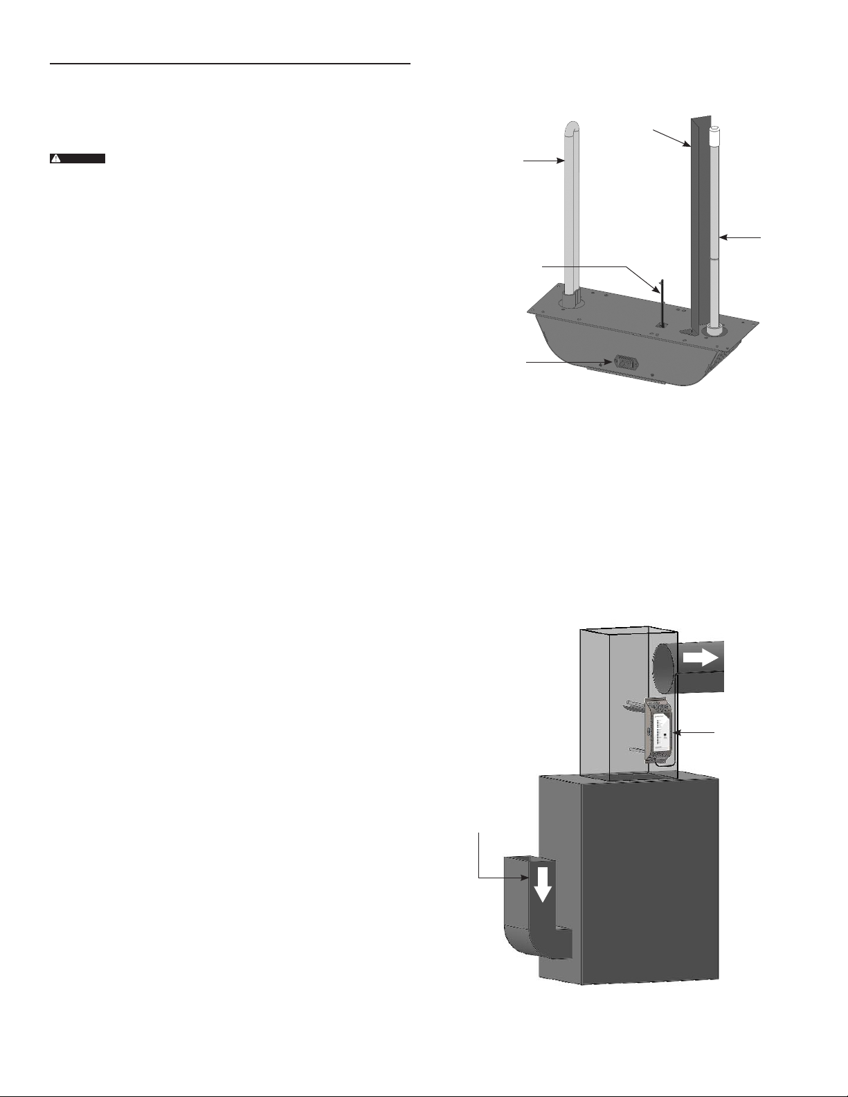
ASSEMBLING THE COMAIR 20T ...............................................4
FIGURE 2 - EXTERNAL COMAIR 20T COMPONENTS.................4
CHOOSING AN INSTALLATION LOCATION................................4
FIGURE 3 - COMAIR 20T INSTALLATION LOCATIONS ...............4
COMAIR 20T INSTALLATION...........................................................5
FIGURE 4 - HOW TO FLIP THE COVER ORIENTATION................5
FIGURE 5 - COVER ORIENTATION OPTIONS..............................5
FIGURE 6 - AIRFLOW SENSITIVITY JUMPER............................5
FIGURE 7 - SETTING THE COMAIR 20T.....................................6
TABLE 1 - CONTROL BOARD DIP SWITCH SETTINGS ................6
ADJUSTING THE COMAIR 20T - WITHOUT THE AMBIENT
OZONE CONTROLLER..............................................................7
TABLE 2 - MODE SELECTION GUIDANCE - WITH THE AMBIENT
OZONE CONTROLLER..............................................................7
TABLE 3 - AMBIENT OZONE CONTROLLER CONNECTIONS......7
TABLE 4 - DIP SWITCH SETTINGS TO USE AMBIENT OZONE
CONTROLLER..........................................................................7
TABLE 5 - MODE SELECTION GUIDANCE WITH AMBIENT ..........
OZONE CONTROLLER..............................................................7
OPTIONAL ACCESSORIES - REMOTE DISPLAY AND AMBIENT
OZONE CONTROLLER..............................................................8
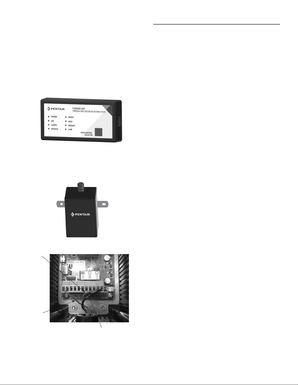
FIGURE 8 - REMOTE DISPLAY ..................................................8
FIGURE 9 - AMBIENT OZONE CONTROLLER.............................8
MAINTENANCE ..............................................................................8
FIGURE 10 - MAIN COMPONENTS .............................................9
TROUBLESHOOTING .................................................................... 10
APPENDIX A - SPECIFICATIONS .................................................... 11
APPENDIX B - PARTS LIST............................................................. 11
APPENDIX C - WARRANTY INFORMATION..................................... 12
WARNING
Read all instructions and warnings before installing or operating
this product - Call 805-549-9724 for additional free copies of this
manual.
IMPORTANT - PLEASE READ
• This installation and operation guide is written to assist in the
installation, operation, and maintenance of the ComAir 20T
product.
• Please read this manual carefully and in its entirety before
proceeding with any installation, operation, or maintenance
procedure associated with this equipment. Failure to follow
these instructions could result in personal injury, damage to the
equipment, or reduced product performance.
• In an ongoing effort to improve reliability and operating
eciency, ClearWater Tech, LLC may nd it necessary to make
changes to its products. Therefore, the information contained
in this manual may not conform in every respect to earlier
versions of ClearWater Tech, LLC systems found in the eld. If
you have any questions, please contact the ClearWater Tech,
LLC dealer or the ClearWater Tech, LLC service department.
SAFETY
This Pentair® ComAir 20T system must be installed by a licensed
professional in accordance with all applicable codes and standards
for the jurisdiction in which it is installed. In addition, all plumbing
attached to or used with the ComAir 20T must be installed by a
licensed, professional plumber.
This section of the manual contains safety warnings
and must be read, understood, and applied during
installation, operation, and maintenance of the
ComAir 20T system. Failure to obey the warnings and
instructions herein may present potential health and
safety hazards resulting in death or serious bodily injury
to personnel and damage to the equipment. The safety
information contained in this manual is intended to be
read thoroughly.
Inspect the ComAir 20T system regularly for cracks or
other damage. Cracks and damage can result in leakage
or rupture failure. If the damage is found, immediately
shut down the system until the damage has been
thoroughly inspected and repaired. Do not continue to
operate the system.
Ozone is a colorless gas with a strong odor. Ozone can
be hazardous and can cause severe respiratory toxicity.
Breathing ozone can damage the lungs and cause
headaches, chest pain, coughing, shortness of breath,
and throat irritation. Higher exposure can cause uid
buildup in the lungs (pulmonary edema). Ozone can also
worsen chronic respiratory diseases such as asthma
and compromise a person’s ability to ght respiratory
infections. In the event of ozone leakage, move to fresh
air immediately.
Ensure any cleaning, repair, or ozone equipment is
done by qualied, correctly trained personnel.
GROUNDING INSTRUCTIONS: This system must be
grounded. In the event of a malfunction or breakdown,
grounding will reduce electric shock risk by providing
a path of least resistance for electric current. This
system is equipped with a cord having a system-
grounding conductor and a grounding plug. The plug
must be plugged into an appropriate outlet installed
and grounded in accordance with all local codes and
ordinances.
Improper connection of the system-grounding
conductor can result in a risk of electric shock. Check
with a qualied electrician or service representative if
you doubt whether the system is properly grounded. Do
not modify the systems plug; if it does not t the outlet,
have a proper outlet installed by a qualied technician.
Children should be supervised to ensure that they do
not play with the system.
2 • Pentair® ComAir 20T Installation and Operation Guide
WARNING:
WARNING:
DANGER:
WARNING:

THEORY OF OPERATION
AND PRODUCT DESCRIPTION
The Pentair® ComAir 20T is a powerful, commercial-grade
HVAC sterilization system designed to reduce indoor airborne
contaminants and unwanted odors, leaving behind fresh, cleaner
air. Installed in the centralized HVAC system of your commercial
space, the ComAir 20T provides "double-layered" protection with
two specially-designed ultraviolet (UV) lamps.
The ozone lamp creates light at 185nm, which is easily absorbed by
oxygen molecules. This added energy causes the oxygen molecules
to break apart into single oxygen atoms, which then combine with
other oxygen molecules to create ozone.
The germicidal lamp creates light at 254nm, which is absorbed by
DNA molecules in unwanted pathogens. The extra energy disrupts
the DNA molecule inhibiting the pathogen from reproducing.
The ComAir 20T is designed to install easily into the air duct,
placing the ozone UV lamp, germicidal UV lamp, and an airow
sensor into the air stream. As air passes through the air duct, the
airow sensor will initiate power to both UV lamps. Incoming air will
rst pass by the high-powered germicidal UV lamp.
The ComAir 20T will reduce pathogens in the air stream as the
Ultraviolet light disrupts their DNA. As the air continues to travel
down the duct, the air will pass by the ozone lamp, where a small
amount of ozone will be created in the airow. This ozone will
then travel with the air through the ducting, where its oxidation of
pathogens and other contaminants occurs.
An optional ozone sensor allows the ComAir 20T to regulate the
ozone output levels produced within the ducting. This adds an extra
level of assurance against pathogens in the occupied space. An
optional remote display allows the ComAir 20T to be monitored and
controlled in a more convenient location.
Typical ComAir 20T Installation
Figure 1
Optional
Remote
Display
Optional Ozone
Controller
ComAir 20T
INSTRUCTIONS
Always make sure the Pentair® ComAir 20T system is unplugged
during installation or service.
The ultaviolet light (UV) produced by the UV lamps
is harmful to the eyes. Do not look directly at the
lamps. Should it become necessary to look at
the lamps, use UV-protected sunglasses.
1. Save these instructions. Before using, please read the owner's
manual carefully.
2. Disconnect power before servicing.
3. Do not operate the system with the cover removed.
4. Do not use an extension cord.
5. ComAir 20T should be cleaned with a damp cloth. Avoid using
harsh chemicals, abrasives, or cleaners.
The system has only been evaluated for mechanical,
electric shock, and re hazards. The method to control
ozone release or the effectiveness of the water
treatment has not been investigated.
For indoor use only. This unit is not intended for
outdoor use.
6. Fully install system in the duct before plugging it into power.
7. This system is not intended for use by persons with reduced
physical, sensory or mental capabilities, or lack of experience
and knowledge.
8. If the supply cord is damaged, it must be replaced by the
manufacturer, its service agent, or similarly qualied persons in
order to avoid a hazard.
WARNING:
WARNING:
WARNING:
Pentair® ComAir 20T Installation and Operation Guide • 3

Assembling the ComAir 20T
Remove the screws from the cover of the unit and open the cover.
Choosing an Installation Location
The ComAir 20T may be installed either in the main return duct, or
the main supply duct as shown in gure 4 below. When installing
on the supply side, locate it as far away from the heating source as
practical while remaining in the main air stream.
INSTALLATION PROCEDURES
Unpacking
Carefully remove the parts from the package. The lamps are fragile
and proper care must be taken when removing the packaging that
is placed around them.
Do not touch the lamps with your bare hands, as oils
from your hands create "hot spots," which reduce the
lamp life. In case of contact with the lamp, wipe the
lamp clean with a soft cloth dampened with rubbing
alcohol.
Make sure all components are in the box before the installation
process. In addition to this manual, you should have the following
parts:
• ComAir 20T unit
• (1) Ozone lamp
• (1) Germicidal lamp
• (1) Lamp shield
• (1) Airow sensor PC
• (4) Self-tapping screws
• (1) Installation template
• (1) Power cord
1. See gure 2 for locations of components. Install lamp shield
by using the hardware that is attached to the main unit. Attach
the shield to the main unit and tighten the two nuts.
2. Install the ozone lamp.
a. Loosen the lamp lock nut from the lamp holder by turning it
counterclockwise and remove.
b. Remove the metal washer and the rubber bushing from
the lamp holder and install the rubber bushing on the lamp
base.
c. Slide the lamp into the lamp opening. Handle lamp by the
end cap.
d. Re-install the metal washer and lamp lock nut.
e. Carefully tighten the lamp lock nut.
f. Connect the lamp connector to the end of the lamp.
g. Make sure the other side of the lamp connector is inserted
completely on the daughter board lamp pins.
3. Install the germicidal lamp.
a. Remove nuts and washers from the mounting studs.
b. Place the two rubber washers on the mounting studs rst.
c. Slide the lamp into the main unit and align so the mounting
ears on the lamp go through the mounting studs on the
main unit.
d. Install the hard-plastic washers and nuts.
e. Tighten the nuts snugly but do not over tighten.
f. Connect the lamp connector to the end of the lamp.
g. Make sure the other side of the lamp connector is inserted
completely on the main ballast board lamp pins.
4. Insert the airow sensor PCB into the hole on the bottom of the
unit. The sensor connector is keyed so it can only go in one way.
5. Ensure the ribbon cable is inserted completely in the main
ballast board and the control board on the cover.
ComAir 20T Installation Locations
Figure 3
Return Side
Supply Side
Figure 2
ComAir 20T External Components
Ozone
Lamp
Germicidal
Lamp
Power Inlet
Airow Sensor
Lamp
Shield
WARNING:
4 • Pentair® ComAir 20T Installation and Operation Guide

ComAir 20T Installation
While performing installation procedures all power to the unit must
be ‘Off’ and there should be no airow through the heating/cooling
system.
1. When installing the ComAir 20T, a template may be used.
The template is included in the shipping box. Refer to gure 4
for mounting locations.
2. If possible, install the unit, so the airow passes over the
germicidal lamp rst and then passes over the ozone
lamp. Reverse the cover by removing the hinge nuts
and attaching the hinge cover to the opposite side of
the chassis. This will allow the cover to be oriented so it is
easy to read and operate the unit once it is installed.
3. Attach the installation template to the ductwork using tape.
4. Cut out openings in ductwork for the unit. See template for
steps and recommended tools.
5. There are 4 mounting holes provided inside the cover and 4
mounting holes provided outside the unit. Either
set of holes are acceptable to use. Position the unit into
ductwork and secure with the self-tapping screws provided
using a 5/16” nut driver.
6. Close the cover and secure it with the cover screws.
7. Connect main power to a non-switched power supply
(90-265 VAC). Note: On initial startup, the ‘power, air,
germicidal, ozone and low’ lights will remain on for 30 to
120 seconds. After this time, the ‘Air, Germicidal and Ozone’
lights will turn ‘off’. If the lights do not turn ‘Off,' the airow
sensitivity might need to be adjusted to be less sensitive.
The unit can be set for low sensitivity (more airow is
required to turn the system ‘on’), M - Medium sensitivity
and H - High sensitivity (less airow is required to turn the
system ‘On’). See gure 7 for location of airow sensitivity
jumper.
8. Turn the ‘On’ heating/cooling system and allow it to operate for
ve minutes, at this time the ‘Air, Germicidal and Ozone’
lights should illuminate. If the lights do not turn ‘On’, the
airow sensitivity might need to be adjusted to be more
sensitive. See gure 7 for the airow sensitivity jumper.
9. Turn the ‘Off’ heating/cooling system; the ComAir 20T will
shut-down within 5 to 30 seconds. After this time, the
‘Air, Germicidal and Ozone’ lights will turn ‘Off.'
The ‘Power’ and ‘Low’ lights will remain on when the system is
not in operation.
10. The ComAir 20T is now ready for use.
Note: Ozone air treatment occurs only when air is circulating
through the heating/cooling system. For maximum effectiveness,
turn the thermostatic controller switch from the ‘AUTO’ position
to the ‘ON’ position. The switch is located on the thermostat.
Open windows or doors and dirty ductwork may diminish the unit’s
effectiveness.
How to Flip the Cover Orientation
Figure 4
Remove cover
and move
to other side
Remove bracket and
move to other side
Airow Sensitivity Jumper
Figure 6
Cover Orientation Options
Airow
Airow
Figure 5
Pentair® ComAir 20T Installation and Operation Guide • 5

Setting the ComAir 20T
Inside the cover on the control board are 5 dip-switches that allow
the control board to be congured for your particular installation.
Switch When Positioned Left (Off) When Positioned Right (On)
Switch 1 The 10 LEDs will indicate the signal level coming into the
control board from the ambient ozone controller inputs. The 10 LEDs will indicate the current mode of the unit.
Switch 2 The unit will expect a signal from an ambient ozone
controller to regulate the ozone output.
The unit will not use an ambient ozone controller to
regulate the ozone output. It will provide output equal
to 25%, 50%, 75% or 100% of the max lamp output
determined by mode setting.
Switch 3
The ambient ozone controller connected to the unit
provides a continuous voltage or current signal
proportional to the ozone. For example, the
controller provides a 0-5V signal with 0 volts equal to 0
ppm ozone and 5 volts equal to 0.5 ppm of ozone.
The ambient ozone controller connected to the unit
provides a relay signal. The relay is closed when the
ozone level is below the set point set on the controller
and open when the ozone level is above the setpoint set
on the controller.
Switch 4
The ambient ozone controller connected to the
unit is in a higher range:
0-5V with 5V = 0.5 ppm
Or
4-20mA with 20mA = 1 ppm
The ambient ozone controller connected to the
unit is in a lower range:
0-2V with 2V = 0.1 ppm
Or
4-20mA with 20mA = 0.1 ppm
Switch 5 The unit is ready to communicate with the remote
display through the RJ-45 connector
The unitis sending serial data through the RJ-45
connector that can communicate with an external
serial device.
Moving from the top of the control board down:
Table 1 - Control Board Dip Switch Settings
Control Board Dip Switches
Figure 7
6 • Pentair® ComAir 20T Installation and Operation Guide

Table 3 - Ambient Ozone Controller Connections
To use the ambient ozone controller, the switches on the
ComAir20T Control Board must be set correctly:
Table 4 – Dip Switch Settings to use Ambient Ozone Controller
Switch 5 will be set based on whether a remote display is
connected or if the unit is communicating to a serial device. See
the “Setting the ComAir 20T” section.
Once the system is powered up, the desired ozone output can
be selected using the button on the cover of the unit or optional
remote display. Holding down the button on the cover or an optional
remote display for 3-4 seconds activates boost mode. After 30
minutes, the unit will automatically go back to the mode it was in
before it went into boost mode.
Table 5 – Mode Selection Guidance with Ambient Ozone Controller
The controller detects levels over the desired ozone mode
selection set point (see Table 5 above), the ozone lamp will begin
to dim. If the ozone lamp is as dim as possible and the controller is
still detecting ozone above the desired ozone level, the unit will turn
off the ozone lamp until the ozone level drops below the desired
ozone mode selection set point. While in this mode, the ozone lamp
indicator LED will ash.
Adjusting the ComAir 20T - Without the Ambient
Ozone Controller
The output level adjustment push button is on the front cover. The
settings are low, medium, high, and boost. Press the button on the
cover of the unit to cycle the settings from low to boost and then
back to low. The unit will default to the low setting on initial
power-up.
Table 2 - Mode Selection Guidance, without Ambient Ozone
Controller
Note: Buildings with heavy tobacco smoke or other strong odors
can use higher settings than the recommendations in Table 2.
When the unit is in low mode, the ozone lamp will cycle ‘On’ and ‘Off’
every 5 minutes. This is to create an ozone output level lower than
is possible by simply dimming the ozone lamp. While in this mode,
the ozone lamp indicator LED will ash.
Adjusting the ComAir 20T - With the Ambient Ozone
Controller
An optional ambient ozone controller is available that detects the
ozone concentration in the duct of the heating/cooling duct. These
instructions will describe how to connect and use the Pentair
ambient ozone controller correctly. If a different ozone sensor is
used, please refer to the instruction manual for that sensor, and
“Setting the ComAir 20T” section above to properly set up the
sensor with the unit.
The unit will read the signal the controller's signal and adjust the
ozone output to maintain a constant ozone level. The connections
for the controller are on the unit control board mounted to the
cover. The cover must be opened to access the control board. A
three-conductor cable with wire sizes of 22 gauge or thicker is
recommended for the connection. The cable should be routed
through the strain relief mounted on the cover of the unit. See
gure 11.
The ambient ozone controller should be mounted on the closest
supply register to the unit. The sensor box requires a hole in the
duct for the sensor to t into and 2 holes to be drilled to attach to
the duct with sheet metal screws. A template can be used to locate
the holes is provided with the controller.
Mode Ozone
Output %
HVAC Unit
Capacity
Space Square
Footage
Low 25% 5 - 8.75 Tons 1500 – 2600 ft2
Medium 50% 8.75 – 12.5 Tons 2600 – 3750 ft2
High 75% 12.5 – 16.25 Tons 3750 – 4900 ft2
Boost 100% 16.25 – 20 Tons 4900 – 6000 ft2
ComAir 20T Connecton Controller
Connection Suggested Wire Color
12V V+ Red
GND GND Black
Sig/Relay 0-5V 0-5V Green
Switch Position Setting
Switch 1 Right (On) LEDs Show Mode
Switch 2 Left (Off) Controller Connected
Switch 3 Left (Off) Controller is Continuous Signal
Switch 4 Left (Off) Controller is Higher Range
Level Ozone Output
Low 0.03 ppm
Medium 0.05 ppm
High 0.08 ppm
Boost Sensor is ignored, maximum output for 30 minutes
Pentair® ComAir 20T Installation and Operation Guide • 7

Optional Accessories - Remote Display and Ambient
Ozone Controller
An optional remote display is available. The remote display provides
all of the indicator lights and an output level selection button that
can place in a convenient location. It is connected to the unit by
a cable with RJ45 connectors. Plug one end of the cable into the
end of the remote display (see gure 8) and the other end into the
RJ45 connector on the unit control board mounted to the cover
(see gure 10). Route the RJ45 cable through the strain relief on the
cover. The cover must open to access the control board.
Remote Display
Figure 8
Ambient Ozone Controller
MAINTENANCE
Cleaning the Lamps
Recommended every 12 months
1. Disconnect main power to the ComAir 20T.
2. Remove the screws from the cover of the unit and open.
3. Ozone lamp:
a. Disconnect the lamp connector from the end of the ozone
lamp.
b. Loosen the lamp lock nut from around the end of the lamp by
turning it counterclockwise and remove (pliers may be
required).
c. Remove the metal washer.
d. Remove the lamp by grasping the rubber bushing around
the end of the lamp. With a gentle rocking motion, loosen
the bushing from its seat and carefully slide it straight out.
e. Using a soft cloth dampened with rubbing alcohol, wipe
down the ozone lamp. If there is a large buildup of dust
particles, you may wish to use a can of compressed air
rst to remove most of the dirt.
f. Slide the ozone lamp back into the lamp opening. Handle
lamp by the end cap.
g. Reinstall the metal washer and lamp lock nut. Carefully
tighten the lamp lock nut.
h. Reconnect the lamp connector to the end of the lamp.
4. Germicidal lamp:
a. Remove the lamp connector.
b. Remove screws and washers that hold the lamp to the main
unit.
c. Slide the lamp out.
d. Using a soft cloth dampened with rubbing alcohol, wipe
down the germicidal lamp. If there is a large buildup of dust
particles, you may wish to use a can of compressed air rst
to remove the most of the dirt.
e. Make sure the rubber washers on the mounting studs are
in place and not damaged. If they are damaged, replace
before reinstalling the germicidal lamp.
f. Slide the germicidal lamp in.
g. Install the plastic washers and nuts on the mounting studs.
Tighten the nuts snugly.
h. Reconnect the lamp connector.
i. Close the cover and secure it with screws.
j. Plug the power cord into the wall outlet.
Figure 9
12V Red
O-5V
Green
GND Black
8 • Pentair® ComAir 20T Installation and Operation Guide

Replacing the Lamps:
Recommended every 24 months
Note: Use only ClearWater Tech-approved lamps for replacement.
Standard off-the-shelf lamps are not compatible with your ComAir
20T unit.
1. Disconnect main power to the ComAir 20T.
2. Remove the screws from the cover of the unit and open.
3. Ozone lamp:
a. Disconnect the lamp connector from the end of a lamp.
b. Loosen the lamp lock nut from around the end of the lamp
by turning it counterclockwise and remove (pliers may be
required).
c. Remove the metal washer.
d. Remove the lamp by grasping the rubber bushing around the
end of the lamp. With a gentle rocking motion, loosen the
bushing from its seat and carefully slide it straight out.
e. Remove the rubber bushing from the old lamp and install it
on the new lamp.
f. Slide the new lamp back into the lamp opening. Handle lamp
by the end cap.
g. Reinstall the metal washer and lamp lock nut. Carefully
tighten the lamp lock nut.
h. Reconnect the lamp connector to the end of the lamp.
4. Germicidal lamp:
a. Remove the lamp connector.
b. Remove screws and washers that hold the lamp to the main
unit.
c. Slide the lamp out.
d. Make sure the rubber washers on the mounting studs are
in place and not damaged. If they are damaged, replace
before installing the new lamp.
e. Slide the new lamp in.
f. Install the plastic washers and nuts on the mounting studs.
Tighten the nuts snugly.
g. Reconnect the lamp connector.
h. Close the cover and secure the cover with the screws.
i. Plug the power cord into the wall outlet.
j. Reset the service timer by pressing the ozone output
level button and holding it for approximately 20 seconds.
After 5 seconds, the LEDs will begin to turn on one at a time
until all 10 lower LEDs are on. Once they all turn
on, the service LED will turn off.
Figure 10
Main Components
Ozone
Controller
Input
Main Ballast
Board
Control Board
Power
Entry
Module
Remote Serial
RJ45 Connector
Ozone Lamp
Ozone
Daughter
Board
Germicidal Lamp
Cover Strain
Relief
Pentair® ComAir 20T Installation and Operation Guide • 9

TROUBLESHOOTING
Problem/Symptom Possible Cause Solution
No power • No power to system
• Fuse blown
• Check main power to system
• Check fuse, replace if blown
Unit doesn’t turn on with
airow
• No airow present
• Airow sensitivity needs adjustments
• Check the unit to ensure it is supplying airow
• Adjust the airow sensitivity jumper to be more sensitive
Unit doesn’t turn off with no
airow
• Unit is on
• Airow sensitivity needs adjustment
• Check the unit to ensure the airow is off
• Adjust the airow sensitivity jumper to be less sensitivity
Ozone LED light is not turning
on
• No airow present
• Blue shutdown LED illuminated
• Yellow shutdown LED illuminated
• Red shutdown LED illuminated
• If there is a problem with the ozone
lamp the ozone LED will not
illuminate and the service light will
begin to blink
• Check the HVAC system to ensure it is supplying airow
• Control board is shutting down the ozone lamp
• Lamp laments are damaged, replace the ozone lamp
• High ambient temperature
• Replace the ozone lamp
Germicidal LED light is not
turning on
• No airow present
• Blue shutdown LED illuminated
• Yellow shutdown LED illuminated
• Red shutdown LED illuminated
• If there is a problem with the germicidal
lamp, the germicidal LED light will not
illuminate and the service light will
begin to blink.
• Check the HVAC system to ensure it is supplying airow
• Control board is shutting down the germicidal lamp
• Lamp laments are damaged, replace the germicidal lamp
• High ambient temperature
• Replace the germicidal lamp
Ozone LED light is blinking • The control board will occasionally turn
off the ozone lamp to reduce the ozone
output. When this happens, the ozone
LED light will blink.
• This is normal; there is no problem.
10 • Pentair® ComAir 20T Installation and Operation Guide

• System (Model/Part No.)
HVAC40 unit only
HVAC45 unit with remote
• Ozone Output
0.08 ppm max @3500 CFM; actual ozone output depends on
what else is in the air
• Ozone Lamp
185 nm, hot lament, average life 20k hours
• Germicidal Lamp
254 nm, hot lament, average life 20K hours
• Power
90-270VAC/50-60HZ; 180 watt at maximum output setting
• F
- High Sensitivity ~ 75 ft/minute airow
- Medium Sensitivity ~ 190 ft/minute airow
- Low Sensitivity ~ 350 ft/minute airow
• Serial Output
9600 bits per second baud rate; 8 bits, no parity
• Output Voltage
12V, 0.5A max
• Voltage Input
0-5V, <0.1mA
• Current Input
4-20mA Isolated circuitry
• Minimum Duct Size
18" (45.72 cm)
• Dimensions
15.5" H x 5.5" W x 20" D (38 cm x 14 cm x 50.8 cm)
• Exposed Size (outside of duct)
15.0" H x 5.5" W x 3.5" D
(38 cm x 14 cm x 8.9 cm)
• Weight
5 lbs (2.26 kg)
APPENDIX B - Parts List
Description Part Number
Airow Sensor CCA1182SA
Ozone Lamp LA15
Germicidal Lamp LAHV92
Lamp Shield CWT1178
Fuse FUS15
Main Ballast Board CCA1814SA
Ozone Daughter Board CCA1815SA
Control Board CCA1816SA
Pentair® ComAir 20T Installation and Operation Guidel • 11

For Pentair Product Warranties visit: pentair.com/assets/foodservice-warranty
HVAC40/45 SE21
850 Capitolio Way | Suite E | San Luis Obispo, CA 93401 | United States
P: 805.549.9724 | Toll Free: 800.262.0203 | sales@cwtozone.com | cwtozone.com
All indicated Pentair trademarks and logos are property of Pentair. Third party registered and unregistered trademarks and logos are the property of their respective owners.
© 2021 Pentair. All rights reserved.
850 Capitolio Way | Suite E
San Luis Obispo, CA 93401 | United States
P: 805.549.9724 | Toll Free: 800.262.0203
sales@cwtozone.com | cwtozone.com
All indicated Pentair trademarks and logos are property of Pentair. Third party registered and
unregistered trademarks and logos are the property of their respective owners.
© 2021 Pentair. All rights reserved.
This manual suits for next models
1
Table of contents
Popular Air Cleaner manuals by other brands

Deltech
Deltech PBA-12 instruction manual

Alen
Alen Paralda user manual

cecotec
cecotec TOTALPURE 1000 HANDY instruction manual

HoMedics
HoMedics TotalClean AP-T10 Instruction manual and warranty information

ScentAir
ScentAir ScentWave SWD1001 Installation and operation instructions

Flanders
Flanders High Temperature Rigid Filter PB1003 Specification sheet