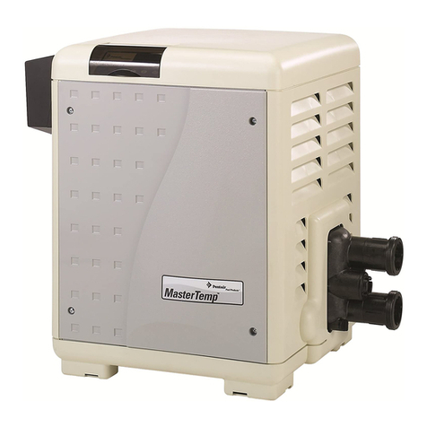
Pentair MiniMax Plus, PowerMax MiniMax User manual

1
Rev. C 12-1-00 P/N 38033
FOR YOUR SAFETY - READ BEFORE OPERATING
Warning: If you do not follow these instructions exactly, a fire or explosion may
result, causing property damage, personal injury or loss of life.
Do not store or use gasoline or other flammable vapors and
liquids in the vicinity of this or other appliances.
For Your
Safety
Improper installation, adjustment, alteration, service or maintenance can cause property
damage, personal injury or death. Installation and service must be performed by a
qualified installer, service agency or the gas supplier.
MiniMax Plus
POOL & SPA HEATERS
SERVICE MANUAL
WARNING
WHAT TO DO IF YOU SMELL GAS
•Do not try to light any appliance.
• Do not touch any electrical switch; do not use any phone in your building.
• Immediately call your gas supplier from a neighbor's phone.
Follow the gas supplier's instructions.
• If you cannot reach your gas supplier, call the fire department.
WARNING
Pentair Pool Products
1620 Hawkins Ave., Sanford, NC 27330 •(919) 774-4151
10951 West Los Angeles Ave., Moorpark, CA 93021 •(805) 523-2400

2
P/N 38033 Rev. C 12-1-00
Table of Contents
Introduction ............................................................................................................... 3
ImportantNotices .......................................................................................................................................................................... 3
SafetyRules .................................................................................................................................................................................. 3
Installation Tips .......................................................................................................... 4
Dimensions.............................................................................................................................. 5
OutdoorInstallationRequirements ................................................................................................................................................ 6
Water Connections ................................................................................................................. 7
ReversingHeaderConnections .................................................................................................................................................... 8
AirRequirements .......................................................................................................................................................................... 9
VentRequirements........................................................................................................................................................................ 9
Gas Connections .................................................................................................................... 10
GasLine/Installation ...................................................................................................................................................................... 10
PipeSizingChart/GasPressureRequirements ............................................................................................................................. 10
Electrical .................................................................................................................................. 11
TransformerWiring Instruction...................................................................................................................................................... 11
Remote Control Wiring .................................................................................................................................................................. 11
ElectricalWiring Schematic............................................................................................................................................................ 12
ElectricalWiring Pictorial................................................................................................................................................................ 13
Operation .................................................................................................................... 14
MillivoltLighting/Operation-Natural&Propane ............................................................................................................................ 14
ChemicalBalance .......................................................................................................................................................................... 15
Maintenance ............................................................................................................... 16
SpringandAutumnOperation ....................................................................................................................................................... 16
WinterOperation ........................................................................................................................................................................... 16
Burner Tray Removal.................................................................................................................................................................... 17
Desooting ...................................................................................................................................................................................... 18
ReinstallingHeatExchanger ......................................................................................................................................................... 19
Glossary...................................................................................................................... 20
Troubleshooting......................................................................................................... 21-32
ElectricalWiringDiagram .............................................................................................................................................................. 33
MillivoltWiringDiagram ................................................................................................................................................................. 34
Test and Adjustments ................................................................................................ 35
MiniMax Plus Exploded View & Parts List............................................................... 36-38
Warranty Information ................................................................................................. Back Cover

3
Rev. C 12-1-00 P/N 38033
MiniMax Plus
Pools and Spa Heater
...For the installer and operator of the MiniMax Plus pool and spa heater. The manufacturer’s warranty may
be void if, for any reason, the heater is improperly installed and/or operated. Be sure to follow the
instructions set forth in this manual.
These heaters are designed for the heating of swimming pools and spas, and should never be employed for
use as space heating boilers, general purpose water heaters, in non-stationary installations, or for the heating
of salt water.
CODES
The installation must conform with local codes or in the absence of local codes with the latest National Fuel
Gas Code, ANSI Z223.1, and the latest edition of the National Electrical Code, NFPA 70.
Installation in Canada to be made in accordance with the latest CAN/CGA-B149.1 or .2 and CSA C22.1
Canadian Electric Code, part 1.
Important Notice
Safety Rules
1. Spa or hot tub water temperatures should never
exceed 104° F (40° C). A temperature of 100° F
(38° C) is considered safe for a healthy adult.
Special caution is suggested for young children.
2. Drinking of alcoholic beverages before or
during spa or hot tub use can cause drowsiness
which could lead to unconsciousness and
subsequently result in drowning.
3. Pregnant women beware! Soaking in water
above 102° F (39° C) can cause fetal damage
during the first three months of pregnancy
(resulting in the birth of a brain-damaged or
deformed child). Pregnant women should stick
to the 100° F (38° C) maximum rule.
Should overheating occur or the gas supply fail to shut off, turn off the manual gas control valve to the
appliance. Do not use this heater if any part has been under water. Immediately call a qualified service
technician to inspect the heater and to replace any part of control system and gas control which has been
under water.
WARNING
4. Before entering the spa or hot tub, the user
should check the water temperature with an
accurate thermometer. Spa or hot tub
thermostats may err in regulating water
temperatures by as much as 4° F (2.2° C).
5. Persons with a medical history of heart disease,
circulatory problems, diabetes or blood pressure
problems should obtain their physician's advice
before using spas or hot tubs.
6. Persons taking medication which induce
drowsiness, such as tranquilizers, antihistamines
or anticoagulants should not use spas or hot
tubs.

4
P/N 38033 Rev. C 12-1-00
Installation Tips
DO NOT INSTALL HEATER UNDER ANY ROOF OVERHANG
NOT HAVING A PROPER RAIN GUTTER.
CACA
CACA
CAUTIONUTION
UTIONUTION
UTION
DO NOT PLACE GAS SUPPLY LINE UNION COUPLING
INSIDE OF HEATER JACKET.
(Follow Recommendations of National Fuel Gas Code NFPA 54.)
CACA
CACA
CAUTIONUTION
UTIONUTION
UTION
DO NOT RESTRICT ACCESSTO HEATERWITH PIPING.

5
Rev. C 12-1-00 P/N 38033
Dimensions
28"
"D"
DIM
"A" DIM.
5-1/2
3
"B" DIM.
POOL
POWERPOOLTEMPERATURE
HOT COLD COLD
SPA/AUXILIARYTEMPERATURE
HOT
SPA
OFF
"E" DIM.
TM
"C"
DIM.
POWER PRESSURE HI-LIMITHEAT
2
1
21
HIGHPERFORMANCE HEATER
TM
21
1
2
"A" DIM.
"B" DIM.
32
5-1/2
3
HIGH PERFORMANCE HEATER
ledoMmiD"A"miD"B"
051.ni8/771.ni½6
002/591.ni8/702.ni½9
052.ni8/732.ni½21
003.ni8/762.ni½51
053.ni8/792.ni½81
004.ni8/333.ni8/322
ledoMmiD"A"miD"B"miD"C"miD"D"
051.ni8/771.ni½6.ni¾7.ni¾93
002/591.ni8/702.ni½9.ni01.ni¾24
052.ni8/732.ni½21.ni01.ni¾24
003.ni8/762.ni½51.ni¼01.ni¾34
053.ni8/792.ni½81.ni31.ni¾74
004.ni8/333.ni8/322.ni71.ni¾15
ledoMmiD"A"miD"B"miD"C"miD"D"miD"E"
051.ni8/771.ni½6.ni31.ni¾25.ni6
002/591.ni8/702.ni½9.ni31.ni8/735.ni7
052.ni8/732.ni½21.ni31.ni8/735.ni7
003.ni8/762.ni½51.ni31.ni55.ni8
053.ni8/792.ni½81.ni31.ni65.ni9
004.ni8/333.ni8/322.ni71.ni¾06.ni01
Outdoorinstallation -stackless
Indoorinstallation- stack(USA only)
Outdoorshelterinstallation(Canada)
Outdoorinstallation-withvent kit
"D"
DIM
"C"
DIM.
5-1/2
3
"A" DIM.
"B" DIM.
SPA/AUXILIARYTEMPERATURE
POOL
POOLTEMPERATURE
HOT COLD
POWER
OFF
SPA HOT
PRESSUREPOWER HEAT
COLD
HI-LIMIT
TM
"E" DIM.
21 1
2
28
HIGHPERFORMANCE HEATER
141
2
107
8
GAS LINE
OPENING
FRONTVIEW SIDEVIEW

6
P/N 38033 Rev. C 12-1-00
Installation - Outdoors
The heater should not be installed closer than 6 inches to
any fences, walls or shrubs at any side or back, nor
closer than 18 inches at the plumbing side. A minimum
clearance of 24 inches must be maintained at the front of
the heater.
Heater must be installed on a non-
combustible floor and at least six inches
from any combustible material or wall.
IMPORTANT!
When installing the heater, consider that high winds can roll over or deflect off adjacent buildings
and walls. Normally, placing the heater at least three (3) feet from any wall will minimize downdraft.
If it must be installed next to a wall, you should consider installing an outdoor vent kit.
Do not install the heater in locations which will permit
the accumulation of leaves or other combustible material
around the base of the heater.
Do not install the heater in a location that will allow
sprinklers to operate near the heater equipment since the
water may cause damage to the controls and/or
electronics.
Do not install the heater under an overhang of less than
three (3) feet from the top of the heater. The area under
the overhang must be open on three sides. Overhangs
must be such that flue products are not diverted into
living spaces. Heaters installed under overhangs must be
protected from direct roof water drainage by gutters and
the like.
NOTE
From the point where the flue products leave the
heater, that point MUST be a minimum of (4)
feet below, and (4) feet horizontally from or (1)
foot above any door, window or gravity inlet to a
building.
24"
DOOR
18"
6"
6"
SHEET METAL
BLOCKS
(LAID WITH ENDS UNSEALED AND JOINTS MATCHED
HOLLOW MASONARY BLOCKS, NOT LESS THAN 4" THICK
HIGHPERFORMANCE HEATER
24 GA. (MIN.) GALVANIZED SHEET METAL.
FOR AIR CIRCULATION). COVER BLOCKS WITH
6" Min.
6" Min.
TM
BASE FOR USE ON
COMBUSTIBLE FLOORS
HOT
POWER
POOLTEMPERATURE SPA/AUXILIARYTEMPERATURE
POOL
SPA
HOT COLD
POWER PRESSURE
HOT
OFF
COLD
HEAT HI-LIMIT
VENTING GUIDELINES
OUTDOOR INSTALLATION
4' Min.
4' Min.(HORIZ.) CLEARANCE
4' Min.(BELOW)

7
Rev. C 12-1-00 P/N 38033
Water Connections
FOR 1½ & 2 in. SCHEDULE 40 PVC PIPE FOR 1½ & 2 in. COPPER PIPE
The MiniMax heater has the unique capability of direct schedule 40 PVC plumbing connections.
NOTE
Bolt the flange and gasket assembly to
the header before gluing.
Pipe
Plastic Bushin
g
Gasket/Sleeve
Gallons Per Minute
ledoM.niM*.xaM
05102021
002/59102021
05203021
00303021
05304021
00404021
mumixamehtdeecxetonoD* .etarwolfdednemmocer
Manual By-Pass
Where the flow rate exceeds the maximum 120
GPM, a manual bypass should be installed and
adjusted.
Gasket
POOL
HEATER
CHECK
VALVE
MANUAL
BY-PASS ISOLATION
VALVE
ISOLATION
VALVE
TO
POOL
Valves
When any equipment is located below the water
level, valves should be placed in the circulation
piping system to isolate the equipment from the
pool or spa.
Check valves are recommended to prevent back
siphon.
CAUTION
When chemical feeders are installed in the
circulation of the piping system, make sure the
feeder outlet line is down stream of the heater, and
is equipped with a positive seal non-corrosive
“Check Valve”, between the feeder and heater.

8
P/N 38033 Rev. C 12-1-00
Reversing Header
Reversible Inlet/Outlet Connections
The MiniMax heater is factory assembled with right
side inlet/outlet water connections. The inlet/outlet
header can be reversed for left side water connections
without removing the heat exchanger.
2. Disconnect the 2 wires from the high-limit
switches except the short jumper wire. Remove
the temperature sensing bulb from the inlet/
outlet header and remove the 2 wires from the
pressure switch.
3. Remove the 4 inlet/outlet header bolts.
4. Remove the return header bolts.
5. Exchange the inlet/outlet header with the return
header. Replace the heat exchanger tube seals.
6. Install the temperature sensing bulb, hi-limit and
pressure switch wires through the hole provided
on the left side of the front panel.
7. Reconnect the 2 high limit wires; the 2 pressure
switch wires and install the temperature sensing
bulb.
1. Remove the inspection plates.
8. Reinstall the inspection plates.

9
Rev. C 12-1-00 P/N 38033
Air Requirements
Vent Requirements
A vent pipe extension of the same size must be
connected to the draft hood and extended at least
two(2)feet above any obstaclewithina 10 foot radius
ofthevent.Thevent should then be capped withan
approvedweather cap.
NOTE
Do not alter the heater draft hood in any way; it
has been designed by the manufacturer and
approved by A.G.A. for maximum efficiency.
To insure efficient venting, use a 45° elbow for
horizontal installation when attaching the vent pipe
to the draft hood.
ledoM
noitsubmoCrofriA .nI.qS noitalitneVriA .nI.qS
051051051
002002002
052052052
003003003
053053053
004004004
Air Requirements
When a heater is installed indoors, two air openings
must be provided. Ideally one opening should be
placed at the bottom and one at the top of the room
to allow for a free flow of air. If other gas
appliances are installed in the same room, you must
check to see that they have been provided with the
proper size openings, otherwise they may use the air
intended for your pool heater.
Vent Installation
The MiniMax heater is shipped standard as
an outdoor stackless unit. To install the
outdoor vent, or the indoor draft hood:
1. Remove the stackless top.
2. Install adapter (with screws).
3. Install the top cover.
4. Install the vent.
5. Use the screws to secure the vent assembly.
Heater
Front
Front
Flue
Collector
Flue
Adaptor
Inner
Panel
Top
Cover
"L"
Bracket
1/4” Rise
per Foot
Air Supply
Gas Combustion
Air Supply
Ventilation
Vent Cap and Pipe
Furnished by Installer

10
P/N 38033 Rev. C 12-1-00
Gas Requirements
Gas Line Installations
Beforeinstallingthe gasline,besureto check which
fueltheheaterhasbeendesignedtoburn.Thisis
importantbecause differenttypesoffuel require
differentpipe sizes.Theratingplateon theheaterwill
indicatewhichfuel the heaterisdesignedtoburn.The
chartonthispageshowswhichsizepipeisrequiredfor
thedistancefromthegas meter/propane tank to the
heater.
NOTE
When sizing gas lines, calculate three (3) additional
feet of straight pipe for every 90 degree elbow used.
Wheninstalling thegasline,avoidgettingdirt,greaseor
otherforeignmaterial in thepipeasthismaycause
damagetothegas valve, whichmayresultinheater
failure.
Thegasmetershouldbesizedtoassurethatit will
supplyenoughgastotheheaterandany other
appliancesthatmaybe used on the samemeter.
Thegas linefromthemeterwill usuallybeofalarger
sizethanthegas valve suppliedwiththeheater.To
assureaslittle restrictionaspossible,theconnecting
fittingsatthemeter should bethesamesizeasthemain
gaslineandthemaingaslineshouldbereducedas
closeto the heater aspossible.
CAUTION
The heater and any other gas appliances must be
disconnected from the gas supply piping system
during any pressure testing on that system.
Theheateranditsgas connection must be leak tested
before placingthe heaterinoperation. Donotuse
flame to test the gas line. Use soapy water or
another nonflammable method.
ledoM
051
002
052
003
053
004
.ni2/1.ni4/3.ni1.ni¼1.ni½1
taNPLtaNPLtaNPLtaNPLtaNPL
'01'04'05'051'051'006 ----
-'02'03'08'521'052'054'006--
-'01'02'05'07'051'052'005'006-
-- '01'03'05'001'002'053'004'006
-- '01'02'03'07'521'052'052'005
--- '01'02'06'001'051'002'054
Testing Gas Pressure
1. Push the power switchto “OFF”.
2. Turnthe gas valve knob to “OFF”.
3. Remove the pressure tap plugontheburnerside of
thegas valve.
4. Attach the Manometer.
5. Turnthe gas valve knob to “ON”.
6. Fire the heater andread the Manometer.
Natural Propane
Maximum inlet gas pressure 10 in. WC 14 in. WC
Minimum inlet gas pressure **5 in. WC 12 in. WC
Normal manifold pressure 4 in. WC 11 in. WC
** 6 WC for 400 model
*All Readings are taken with the heater firing. Any adjustments
made with heater off will give incorrect readings.
Pipe Sized For Length Of Run In Equivalent Feet
WARNING
Do not install the gas line union inside the heater
cabinet. This will void your warranty.
Gas Pressure Requirements*

11
Rev. C 12-1-00 P/N 38033
Transformer and Remote Wiring
Electrical - Rating
NOTE
If any of the original wiring supplied with the heater
must be replaced, the installer must supply No. 18
AWG 105° C., U.L. approved AWM low energy
stranded copper wire or it’s equivalent.
Transformer Wiring Instructions
The transformer is wired at the Factory for 240V.
CAUTION
The heater must be electrically grounded and
bonded in accordance with local codes or in ab-
sence of local codes, with the latest National
Electrical Codes ANSI/NFPA No. 70.
SPA COM POOL TPROBE
OUT RETURN 24 VAC HILMT IGNITION MOD
EXT SWITCH
THERMOSTAT CIRCUIT BOARD
POOL/
OFF/SPA
FRONT PANEL
THERMOSTAT SELECT SWITCH
TFUSE VALVE
REMOTE CONTROL
PRESS
SPA COM POOL TPROBE
OUT RETURN 24 VAC HILMT IGNITION MOD
EXT SWITCH
THERMOSTAT CIRCUIT BOARD
JUMPER REQUIRED IF NO 2 WIRE REMOTE SWITCH
POOL/
OFF/SPA
FRONT PANEL
THERMOSTAT SELECT SWITCH
TFUSE VALVE
REMOTE POOL/OFF/SPA
THERMOSTAT SELECT SWITCH
PRESS
NOTE: When connecting
a remote control to the
MiniMax wiring, you must
install the low voltage
remote wires in separate
conduit from ANY line
voltage wires. Failure to
follow these instructions
will cause the thermostat
relay to react erratically.
Remote Switch Dual Therm IID Only
3Wire Remote
2Wire Remote
Supply voltage
Connect to
these wires
RED
W/with RED
W/with BLACK
BLACK
240V
-
The red tracer and the black tracer wires are
wiredtogether. (Donotconnect thetracer wiresto
anypower.)Connect one power supplywire to the
solidredwire and the otherpowersupply wire to the
solidblackwire.
120V
-
Towire the transformer for 120V, twist the
red and the red tracer wires together and twist the
black and the black tracer wires together. Connect
the 120V power supply wires to these wires, one to
the red/red tracer, and one to the black/black tracer.
WARNING
If the transformer is wired for the wrong voltage
supply, the transformer will fail.

12
P/N 38033 Rev. C 12-1-00
RED
WHT
BLU
MV
PV/MV
PV
GAS VALVE
MV/PV
GND
(BURNER)
24 V
TH-W
( OPT )
SPARK
THERMOSTAT
CIRCUIT BOARD
SPST. EXTERNAL ON/OFF SWITCH
HIGH LIMIT
THERMAL SWITCHES
WATER PRESSURE
SWITCH
JUMPER REQUIRED IF NO REMOTE SWITCH
CONTROL RELAY
CLOSE ON CALL
FOR HEAT
POOL OFF SPA
THERMOSTAT SELECT SWITCH
TEMPERATURE
PROBE
GND
MV
IGNITION MODULE
SPARK IGNITER
IGNITION WIRE
RED
BLU
WHT
THERMAL FUSE
RED
RED
WHT
WHT
PV
ORG
P4 P7 PI0 P11
J4 J7 JI0 J11
J5
J6 J8 J9
P8
P6 P5 P9
25D K .032 D.C TAB
J2 J3
BLK
BLK
PLUG
MV
MV/PV
PV
PLUG
GRN
IGNITION RETURN
F1 F2
W1 W2
MV
PV
PV/MV
6
1
1
1
1
2
2
2
2
3
3
3
4
4
5
L1-1 L1-2
L2-1
L2-2
1111
GRN
WHT
ORG
24V VLV IGN MODULE
AUX.
CONTACTS
TPROBE
SPA COM POOL
EXTERNAL
BOND LUG
CHASSIS
TERMINATE SUPPLY SAFETY GROUND WIRE (GREEN) HERE
GROUND SCREW WITH PAINT CUTTING WASHER
SHEET METAL
INTERCONNECTING WIRING TO APPLIANCE MUST CONFORM TO THE NATIONAL ELECTRICAL
THERMAL FUSE WIRING MUST BE REPLACED WITH UL OR CSA (IF CANADA) APPROVED
UL OR CSA (IF CANADA) APPROVED WIRE, 18 GAUGE, 600V, 105 C TEMPERATURE RATING.
IF ORIGINAL FACTORY WIRING MUST BE REPLACED, INSTALLER MUST SUPPLY
CODE OR SUPERCEDING LOCAL (WIRING) CODES.
WIRE, 18 GAUGE, 600V, 125 C TEMPERATURE RATING..
MiniMax Plus WIRING DIAGRAM
PRESS
HLMT
TFUSE
GRN
WHT/RED
WHT/BLK
BLK
RED
T2
T1
CHASSIS
SHEET METAL
MiniMax Plus I.I.D.Wiring Schematic

13
Rev. C 12-1-00 P/N 38033
MiniMax Plus I.I.D.Wiring Pictorial
IGN RETURN (GRN)
WHT
PACFAB 6800
THERMOSTAT
ELECTRONIC
DUAL
THERMISTOR PROBE
ON / OFF / ON
SWITCH
(WHT)
SPA
(WHT)
POOL (WHT)
COMMON
WHT
WHT
WHT
THERMAL FUSE
ORN
WHT
RED
ORN
BLK
J BOX
GRN
ORN
WHT
RED
BLUE
WHT
BLUE
RED
CHASSIS SHEET METAL
TRANSFORMER
RED
WHT
PRESSURE
SWITCH
WHT
GAS VALVE
IID
RED
RED RED
RED
WHT
IGNITION
MODULE
BLUE
GRN
HILIMITS
HI TENSION
WIRE
IID PILOT
WHT/BLK
WHT/RED
JUMPER
(WHT)
The wiring was crossed from
the Switch to the Board and
we used a Breaker (Reset)
that was external to the
Transformer.

14
P/N 38033 Rev. C 12-1-00
Natural / Propane
Note: This appliance is equipped with an ignition device which automatically lights the pilot. Do
not try to light the pilot by hand.
Starting Operation (I.I.D.)
SAFETY INFORMATION
-- IFYOU SMELL GAS, FOLLOW THESE RULES:
5. Do not light matches or lighter.
6. Do not try to light any appliance.
7. Do not touch any electrical switch and do
not use any phone in your building.
OFF
ON
Gas control knob shown in “ON” position.
Gas
Inlet
1. Set the thermostat to the lowest setting.
2. Push the power switch off.
3. Remove the door.
4. Push in the gas control knob slightly and turn
clockwise to "OFF".
5. Wait (5) minutes to clear out any gas. If you then
smell gas, STOP! Follow the safety information.
If you don't smell gas, go to next step.
6. Turn knob on gas control counterclockwise to "ON".
7. Replace the door.
8. Make sure the pump is running and primed.
9. Push the power switch on.
10. Set the thermostat to the desired setting.
11. The pilot should spark and the pilot should
ignite, then the heater will fire.
12. In new installations where the gas line hasn't
been bled, the pilot and main burner combustion
sequence may be slower than normal.
13. If the heater does not operate as it should, in a
reasonable amount of time, read the Trouble-
shooting Guide portion of this manual.
SAFETY LOCKOUT:
This MiniMax Propane Heater is equipped with a 100% safety lockout feature. If the pilot does not light
within a maximum of 90 seconds,lockout will occur.
Millivolt Lighting Instructions
1. Push in gas control knob slightly and turn clock-
wise to "OFF".
2. Wait five (5) minutes to clear out any gas. If you
then smell gas, STOP! Follow information on this
page. If you don't smell gas, go to next step.
3. Turn knob on gas valve counterclockwise to "Pilot".
4. Push the control knob all the way down and hold in.
Immediately light the pilot with Presslite match-
less ignition system by pressing the red igniter
button (located at panel next to the gas valve).
Continue to hold the control knob in for
one (1) minute after the pilot is
lit. Release knob slowly.
Pilot should remain lit.
5. Turn knob to "ON".
6. Reinstall door.
7. Set thermostat to desired temperature.
NOTE
If the pilot will not stay lit after several tries, turn
the gas control knob to "OFF" and call your
service technician or gas supplier.
1. Shut off gas line or propane tank.
2. Immediately call your gas supplier from a
neighbor's phone.
3. Follow the gas supplier's instructions.
4. If you cannot reach your gas supplier, call
the fire department.

15
Rev. C 12-1-00 P/N 38033
Chemical Balance
Pool and Spa Water
Your Pentair Pool Products pool heater was designed
specifically for your spa or pool and will give you many
years of trouble free service provided you keep your
water chemistry in proper balance.
Three major items that can cause problems with your
pool heater are improper pH, disinfectant residual, and
total alkalinity. These items, if not kept properly
balanced, can shorten the life of the heater and cause
permanent damage.
WHAT A DISINFECTANT DOES -
Two pool guests you do not want are algae and bacteria.
To get rid of them and make pool water sanitary for
swimming - as well as to improve the water's taste, odor
and clarity - some sort of disinfectant must be used.
Chlorine and bromine are universally approved by health
authorities and are accepted disinfecting agents for
bacteria control.
WHAT IS A DISINFECTANT RESIDUAL?
When you add chlorine or bromine to the pool water, a
portion of the disinfectant will be consumed in the
process of destroying bacteria, algae and other
oxidizable materials. The disinfectant remaining is
called chlorine residual or bromine residual. Youcan
determine the disinfectant residual of your pool water with a
reliable test kit, available from your local pool supply store.
You must maintain a disinfectant residual level adequate
enough to assure a continuous kill of bacteria or virus
introduced into pool water by swimmers, through the air,
from dust, rain or other sources.
It is wise to test pool water regularly. Never allow
chlorine residual to drop below 0.6 ppm (parts per
million). The minimum level for effective chlorine or
bromine residual is 1.4 ppm.
pH - The term pH refers to the acid/alkaline balance of
water expressed on a numerical scale from 0 to 14. A test
kit for measuring pH balance of your pool water is
available from your local pool supply store; see pH Chart.
If pH becomes too high (over alkaline), it has
these effects:
1. Greatly lowers the ability of chlorine to destroy
bacteria and algae.
2. Water becomes cloudy.
3. There is more danger of scale formation on the
plaster or in the heat exchanger.
4. Filter elements may become blocked.
If pH is too low (over acid) the following
conditions may occur:
1. Excessive eye burn or skin irritation.
2. Etching of the plaster.
3. Corrosion of metal fixtures in the filtration and
recirculation system, which may create brown, blue,
green, or sometimes almost black stains on the
plaster.
4. Corrosion of copper in the heater, which may cause
leaks.
5. If you have a sand and gravel filter, the alum used as
a filter aid may dissolve and pass through the filter.
CAUTION
Do not test for pH when the chlorine residual is
3.0 ppm or higher, or bromine residual is 6.0 ppm
or higher. See your local pool supply store for
help in properly balancing your water chemistry.
Heat exchanger damage resulting from chemical
imbalance is not covered by the warranty.
CAUTION
Muriatic Acid has a pH of about 0. Pure water is 7
(neutral). Weak Lye solution have a pH of 13-14.
RULE: 7.4 to 7.6 is a desirable pH range. It is essential
to maintain correct pH, see pH Control Chart.
ALKALINITY High - Low:
"Total alkalinity" is a measurement of the total amount of
alkaline chemicals in the water, and control pH to a great
degree. (It is not the same as pH which refers merely to the
relative alkalinity/acidity balance.) Your pool water's total
alkalinity should be 100 - 140 ppm to permit easier pH
control.
A total alkalinity test is simple to perform with a reliable
test kit. You will need to test once a week and make proper
adjustments until alkalinity is in the proper range. Then,
test only once every month or so to be sure it is being
maintained. See your local pool dealer for help in properly
balancing the water chemistry.
RULE: Chemicals that are acid lower pH. Chemicals
that are alkaline raise pH.
pHChart
Strongly Acid Neutral Strongly Alkaline
0 1 2 3 4 5 6 7 8 9 10 11 12 13 14
7.2
6.8 7.0 7.4 7.6 7.8 8.0 8.2 8.4
Add Soda, Ash or
Sodium Bicarbonate Add AcidMarginalIdealMarginal
pHControlChart

16
P/N 38033 Rev. C 12-1-00
It is recommended that you check the following at least every six months and at the beginning
of every swimming season.
5. Check wire ends and wire connections. They
should be clean and tight.
6. Check the gas pressure as described in this
manual.
7. To protect controls and cabinet finish, periodi-
cally spray with penetrating oil and wipe off.
Spray with the heater “OFF”; Oil is “Flammable”.
CAUTION
Spring and Autumn Operation
If the pool is being used occasionally, do not turn
the heater completely off. Set the thermostat down
to 65o F. This will keep the pool and the surrounding
ground warm enough to bring the pool up to a
comfortable swimming temperature in a shorter
period of time.
Winter Operation
If the pool won't be used for a month or more, turn
theheateroffat the main gas valve. Wherefreezingis
possible,it is necessary todrainthewater from the
heater. This may bedonebyopeningthedrainvalve
locatedat theinlet/outletheaderallowingall waterto
drainout of the heater. Use compressed airto blow the
wateroutoftheheat exchanger.Also, disconnect the
pressureswitch,thiswill prevent freezedamagetothe
switch.
If the heater has been drained for freezing
condition, do NOT turn "ON" until the system
is circulating water.
1. Examine the vent system. Make sure there are
no obstructions in the flow of combustion and
ventilating air.
2. Inspect the heat exchanger for soot. Clean as
necessary.
3. Remove burner tray and clean burners and main
burner orifices.
4. Keep the heater area clean and free from com-
bustibles and flammable liquids.
3/8 to 1/2 in.
Insulated
Electrode
Blue Flame
Blue Flame
NOTE
Water trapped in the heat exchanger can result in
freeze damage to the exchanger or headers.
Freeze damage is specifically not covered by
the warranty.
CAUTION
Relief Valve
In some installations, a relief valve is required
on the MiniMax Plus. Test the relief valve at
least once a year by lifting the valve lever.
(A.S.M.E. version varies slightly and has the
relief valve pre-installed at factory.)
To winterize,
open drain valve
Relief
Valve
Heater Main
Header
To winterize,
open drain valve
Standard
A.S.M.E.Version
Relief
Valve
Maintenance

17
Rev. C 12-1-00 P/N 38033
Maintenance - Burner Tray Removal
At some time during the life of a heater, you may
need to inspect and repair the parts of the heater that
allows the gas to flow from the gas supply line into
the burners. If the heater won’t fire and you wish to
check these gas controls:
1. Turn off the gas supply.
2. Disconnect the gas union at the heater.
3. Remove the gas pipe installed into the gas
valve.
4. Remove the gas valve holding bracket.
5. Remove the gas valve wires.
6. Disconnect the ignition wire.
7. Slide the burner tray out.
8. You can remove the gas valve if you need to
check the inlet and outlet screens. (You will
have to remove the pilot tubing.)
9. Remove the bracket that holds the burners in
place.
10. Remove each burner and check for any
blockages.
11. Remove the main burner orifices and check for
blockage.
NOTE
If the heater has been off for the winter or has been
installed, but not fired for an extended period of
time, insects will crawl into these orifices and the
pilot orifice and prevent the heater from firing.
12. Remove the pilot orifice and clean it. (Do not
use any sharp object! It will destroy the
designed orifice size!)
NOTE
You can use this procedure if you have to change
fuel-type - natural to propane or vice versa.The
parts needed to convert the MiniMax are: Gas
valve, pilot assembly, main burner orifices
and module.

18
P/N 38033 Rev. C 12-1-00
Maintenance - Desooting
Common Causes of Sooting
1. Low gas pressure.
2. Inadequate air supply or inadequate venting.
3. Foreign material in burners and orifices; dirt,
spider webs, etc.
4. Excessive water flow can cause condensation
which will contribute to sooting.
5. Heater cycling rapidly; fires, shuts down and
refires quickly 30-45 seconds.
To remove a light soot formation without
removing the heater exchanger:
1. Remove burner tray.
2. Remove top, inner lid, flue collector and baffles.
7. If flames burn clean, replace baffles, flue
collector, and top.
CAUTION
DO NOT USE WIRE BRUSH!
3. Using a brush with plastic or wood bristles,
brush the bottom of the tubes and then the top of
the tubes.
4. Spray off residue with water. (Repeat steps 3-4
as needed).
5. Brush off burners.
6. Replace burner tray and baffles, then test fire.
For heavy soot accumulation which cannot
be successfully removed by merely brush-
ing, the heat exchanger must be removed
from the heater.
1. Disconnect the plumbing at the flanges. Remove
the thermistor, hi-limit wires from the inlet
outlet heater.
CAUTION
When lifting the heat exchanger out of the fire box,
use caution so as not to damage the fire wall.
2. Remove the heat exchanger.
3. Place exchanger in an area that won’t be
affected by chemicals or strong detergents.
4. After spraying the exchanger with water, use a
mixture of detergent and water. Pour, spray or
brush on.
5. Rinse the solution off of the tubes and inspect
them, repeat if necessary.

19
Rev. C 12-1-00 P/N 38033
Maintenance - Reinstalling Heat
Reinstalling Heat Exchanger
1. Inspect fire box for damage or cracks that would
allow heat to leak out into the outer cabinet and
controls.
2. Remove any old sealant from fire box.
3. Apply new sealant to the fire box using a quality
industrial grade R.T.V. or equivalent. The
sealant must completely seal the space between
the heat exchanger and fire box, so that when
the heater is firing, heat does not escape to the
outer cabinet.
4. Place heat exchanger into the box and push
down firmly, until the heat exchanger sets
solidly on the fire box.
5. Reconnect the inlet and outlet flange to the
headers (use new flange gaskets), be careful not
to move the heat exchanger and break the seal.
6. Reinstall baffles, flue collector, inner lid and top.
CAUTION
Do not store combustible material, gasoline and
other flammable vapor and liquids in the vicinity
of this or any other appliance.

20
P/N 38033 Rev. C 12-1-00
Glossary
1. BURNER: A device for the final conveyance of gas,
or a mixture of gas and air, to the combustion zone.
2. BUTANE: A hydrocarbon fuel gas heavier than
methane and propane and a major constituent of
liquefied petroleum gases.
3. CIRCUIT BOARD: Interprets signals from potenti-
ometers and thermistor.
4. COMBUSTION: The rapid oxidation of fuel gases
accompanied by the production of heat or heat and
light.
5. COMBUSTION AIR: Air supplied in an appliance
specifically for the combustion of a fuel gas.
6. CUBIC FOOT OF GAS: (Standard Conditions). The
amount of gas which will occupy 1 cubic foot when at
a temperature of 60° F. and under a pressure equivalent
to that of 30 inches of mercury.
7. DRAFT HOOD: (Draft Diverter). A device built into
an appliance, or made part of a vent connector from an
appliance, which is designed to: (1) assure the ready
escape of the products of combustion in the event of no
draft, backdraft, or stoppage beyond the draft hood; (2)
prevent backdraft from entering the appliance; and (3)
neutralize the effect of stack action of a chimney or gas
vent upon the operation of the appliance.
8. DOWNDRAFT: Excessive high air pressure existing
at the outlet of chimney or stack which tends to make
gases flow downward in the stack.
9. FLASHBACK: An undesirable flame characteristic
in which burner flames strike back into a burner to
burn there or to create a pop after the gas supply has
been turned off.
10. FLOATING FLAMES: An undesirable burner
operating condition, usually indicating incomplete
combustion in which flames leave the burner ports to
“reach” for combustion air.
11. FLUE GASES, FLUE PRODUCTS: Products of
combustion and excess air in appliance flues or heat
exchangers before the draft hood.
12. GAS VALVE: A device that allows gas to flow from
the gas supply line into the pilot assembly and into the
main burners after receiving voltage from the module.
13. HEAT EXCHANGER: Any device for transferring
heat from one fluid to another.
14. HIGH LIMITS: Devices installed into the outlet side
of the inlet/outlet header, designed to shut heater off
when water temperature reaches 150° F.
15. IGNITIONWIRE: Heavy duty wire attached to the
module and the pilot ignitor, that carries voltage to the
pilot ignitor and back to the module to signal the gas
valve to open when the pilot flame is established.
16. LIQUEFIED PETROLEUM GASES: The terms
“Liquefied Petroleum Gases” “LPG” and “LP Gas”
mean and include any fuel gas which is composed
predominantly of any of the following hydrocarbons,
or mixtures of them: propane, propylene, normal
butane or isobutane and butylenes.
17. MANIFOLD: The conduit of an appliance which
supplies gas to the individual burners.
18. MODULE: Device that sends signals to the pilot
ignitor and gas valve. The module starts the pilot spark
and main burner sequence.
19. NATURAL DRAFT: The motion of flue products
through an appliance generated by hot flue gases rising
in a vent connected to the furnace flue outlet.
20. NATURAL GAS: Any gas found in the earth, as
opposed to gases which are manufactured.
21. ORIFICE: An opening in an orifice cap (hood),
orifice spud or other device through which gas is
discharged, and whereby the flow of gas is limited and/
or controlled.
22. PILOT IGNITOR: Receives spark from module and
establishes a pilot flame just prior to main burner
ignition.
23. POTENTIOMETER: Registers desired temperature
setting on circuit board.
24. PRESSURE SWITCH: A normally open switch that
closes with adequate water pressure.
25. PRIMARY AIR: The combustion air introduced into
a burner which mixes with the gas before it reaches the
port. Usually expressed as a percentage of air required
for complete combustion of the gas.
26. PROPANE: A hydrocarbon gas heavier than methane
but lighter than butane. It is used as a fuel gas alone,
mixed with air or as a major constituent of liquefied
petroleum gases.
27. SOOT: A black substance, mostly consisting of small
particles of carbon, which can result from incomplete
combustion and appear as smoke.
28. TRANSFORMER: A coil device that changes high
voltage to low voltage.
29. THERM: A unit of heat energy equal to 100,000 Btu.
30. THERMAL CUT OFF: A one shot soldered pill type
fuse that melts and interrupts power to the controls if
the temperature becomes to high in the gas valve area.
31. THERMISTOR: Installed in the inlet/outlet header,
senses water temperature and tells circuit board when
to shut heater off.
32. VENT: A device, such as a pipe, to transmit flue
products from an appliance to the outdoors. This term
also is used to designate a small hole or opening for
the escape of a fluid (such as in a gas control).
33. WATER COLUMN: Abbreviated as W.C. A unit
used for expressing pressure.
Other manuals for MiniMax Plus, PowerMax MiniMax
1
Table of contents
Other Pentair Heater manuals

Pentair
Pentair ETi 400 User manual

Pentair
Pentair ULTRATEMP ETi User manual

Pentair
Pentair FreezGard CCH-1C User manual

Pentair
Pentair ETi 400 User manual

Pentair
Pentair ETi 400 User manual

Pentair
Pentair DAHHL400XA User manual

Pentair
Pentair ETi 400 User manual

Pentair
Pentair MASTERTEMP 125 User manual

Pentair
Pentair ULTRATEMP ETi 220 User manual
Pentair
Pentair MASTERTEMP 200 HD User manual