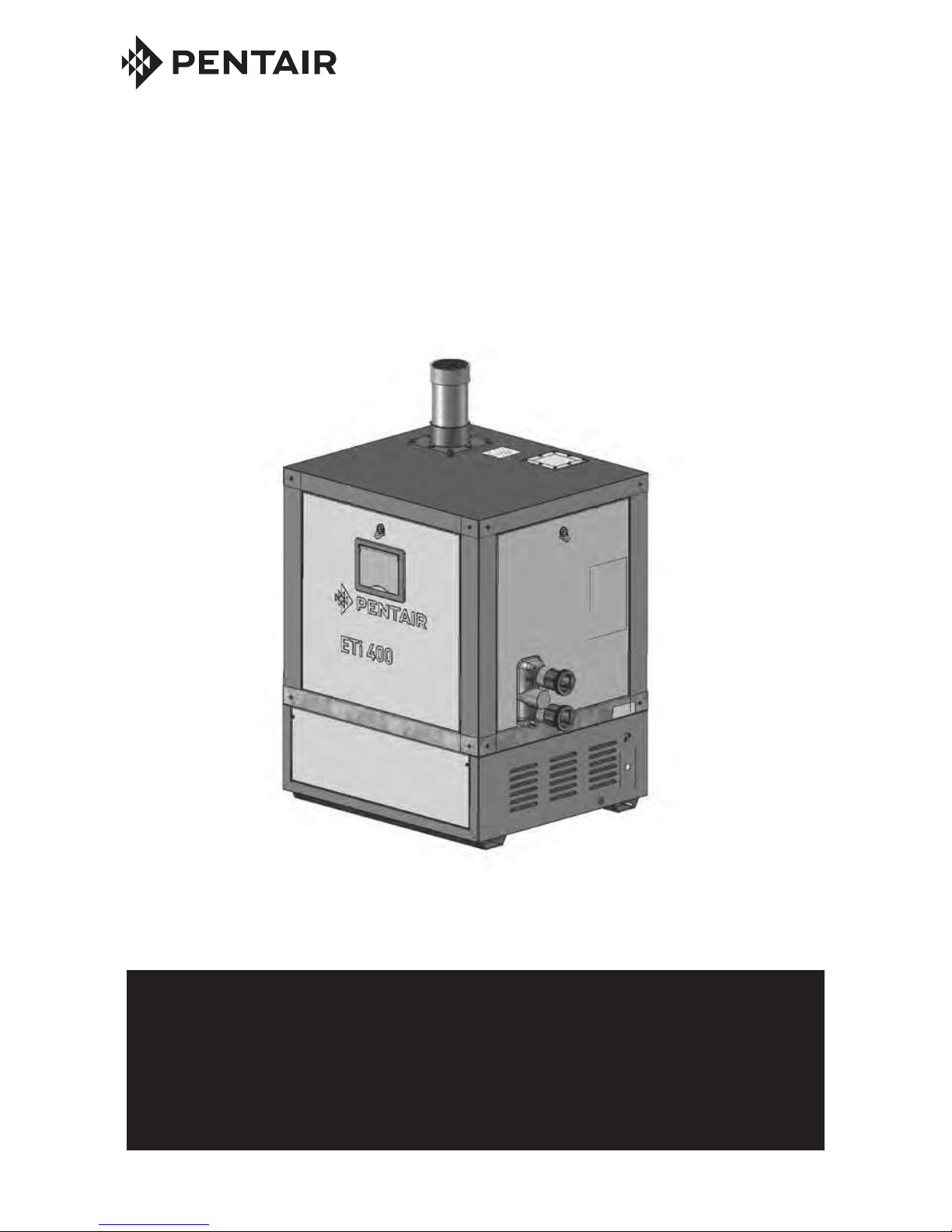
Pentair ETi 400 User manual
Other Pentair Heater manuals

Pentair
Pentair FreezGard CCH-1C User manual

Pentair
Pentair ULTRATEMP ETi User manual

Pentair
Pentair MASTERTEMP 200 HD User manual

Pentair
Pentair MASTERTEMP User manual

Pentair
Pentair MiniMax Plus, PowerMax MiniMax User manual

Pentair
Pentair ETi 400 User manual

Pentair
Pentair MASTERTEMP 125 User manual

Pentair
Pentair DAHHL400XA User manual

Pentair
Pentair ETi 400 User manual

Pentair
Pentair ETi 400 User manual

Popular Heater manuals by other brands

oventrop
oventrop Regucor Series quick start guide

Blaze King
Blaze King CLARITY CL2118.IPI.1 Operation & installation manual

ELMEKO
ELMEKO ML 150 Installation and operating manual

BN Thermic
BN Thermic 830T instructions

KING
KING K Series Installation, operation & maintenance instructions

Empire Comfort Systems
Empire Comfort Systems RH-50-5 Installation instructions and owner's manual

Well Straler
Well Straler RC-16B user guide

EUROM
EUROM 333299 instruction manual

Heylo
Heylo K 170 operating instructions

Eterna
Eterna TR70W installation instructions

Clarke
Clarke GRH15 Operation & maintenance instructions

Empire Heating Systems
Empire Heating Systems WCC65 Installation and owner's instructions