Pentair NOCCHI CPS 10 User manual

IT - ISTRUZIONI ORIGINALI IN LINGUA ITALIANA
IT PAGE 1 EN PAGE 21 ES PAGE 81
FR PAGE 41
NL PAGE 101 RUS PAGE 121DE PAGE 61
CPS 10
CPS 20
PL PAGE 143
Distributed in NZ By:
Freephone 0508 634 34
1
7 Monier Pl, Mt Wellington, Auckland 1060, New
Zealand

21
SUMMARY
GB
CHAPTER DESCRIPTION PAGE
1INTRODUCTION
1.1 PARTICULAR SIGNS 22
1.2 GENERAL INFORMATION 22
1.3 PRELIMINARY CHECKS 22
2 TECHNICAL FEATURES 2.1 FIELD LIMITATIONS 23
2.2 INBOUND SIGNAL FEATURES 23
3 INSTALLATION
3.1 COOLING THE MOTOR 24
3.2 HYDRAULIC CONNECTION 24
3.3 PRESSURISED TANK (EXPANSION VESSEL) 24
3.4 MOTOR PUMP ELECTRICAL CONNECTION 24
3.5 CONNECTING THE PRESSURE UNIT TO THE POWER SUPPLY 25
4FUNCTIONING
4.1 PRODUCT DESCRIPTION 26
4.1.1 MOTOR PUMP 26
4.1.2 PRESSURE UNIT 27
5 PROGRAMMING
5.1 CONTROL PANEL DESCRIPTION 28
5.2 DESCRIPTION OF SIGNALS ON DISPLAY 28
5.3 PROGRAMMING MENU 29
5.3.1 PROGRAMMING CLOCK/DAY 30
5.3.2 SET POINT 30
5.3.3 ADVANCED PARAMETERS 31
5.3.4 INSTALLATION PARAMETERS 32
5.4 MANUAL START OF MOTOR/PRIMING 33
5.5 MANUAL START/STOP 34
6SIGNALS, ALARM STATUS
AND ERRORS
6.1 HISTORY (SAVED) 34
6.2 SIGNAL TABLE 34
6.3 ALARM TABLE 35
6.4 ERROR TABLE 35
7RESETTING AND FACTORY
SETTINGS
7.1 GENERAL SYSTEM RESET 36
7.2 TO RESET FACTORY SETTINGS 37
7.3 SOFTWARE VERSION 37
8 TABLES AND DESIGNS
8.1 DATA PLATE 37
8.2 TO INSTALL THE NEGATIVE SUCTION HEAD 38
8.3 TO INSTALL THE POSITIVE SUCTION HEAD 39
8.4 ELECTRICAL CONNECTION BOARD – POWER BOARD 40
8.5 CONNECTIONS BOARD – CONTROL BOARD 40
- WARRANTY - 144

22
CHaPter 1
CHaPter 2
INTRODUCTION
TECHNICAL FEATURES
GB
• Check the packaging is intact
• Open the packaging and remove the
machine
• Check the machine corresponds to
that ordered
• Check the machine is not damaged
• If you receive an incorrect or
damaged machine, notify PENTAIR
INTERNATIONAL S.A.R.L.or the
authorised dealer within and not after
10 (ten) days from date of purchase
The danger sign indicates the procedures requiring your absolute attention, otherwise you may get an electric shock.
The attention sign indicates the procedures requiring your absolute attention, otherwise you may cause damage to the
machine or equipment connected to it.
Do not use the product in environments with acid, corrosive and/or inflammable gas.
Do not use the motor pump with dangerous liquids.
Incorrect use can dangerously damage the machine or the equipment, as well as result in guarantee forfeiture.
WARNING
ATTENTION
ATTENTION
ATTENTION
ATTENTION
1.1 PARTICULAR SIGNS
1.2 GENERAL INFORMATION
1.3 PRELIMINARY CHECKS
With this manual PENTAIR INTERNATIONAL S.A.R.L.wants to provide the necessary information to install, use and maintain the
CPS inverter coupled with a NOCCHI motor pump.
The CPS module has a single phase power supply and controls a three phase pump by reading the pressure of the electronic
transducer mounted on the collector outlet.
The module enables the operator to select the various system functions using a keyboard and LCD display mounted on same.
The note sign offers important information highlighted outside the text to which it refers.
This manual refers to standard type execution.
For the motor pump refer to the information contained in the specific manuals.
NOTE
NOTE
NOTE
NOTE

23
CHaPter 3
INSTALLATION
GB
• Environmental temperature:
+0 °C to 50 °C
• Temperature of pumped liquid:
refer to the specific motor pump
manual
• Level of CPS protection: IP55
• Level of system protection:
IP55 (if installed on motors with an
IP55 or superior level)
• Pressure field: from 0 to 10 Bar
• Outbound signal: from 0 to 5 Volt
• Maximum operational pressure:
refer to the specific motor pump
manual
• Voltage of inverter:
1x230 Vac ± 10 %
• Voltage of outlet inverter:
3x230 Vac ± 10 %
• Inbound frequency:
50/60 Hz ± 3%
• Connection: 1⁄4 male
• Maximum power at outlet: 1.5 kW
• Maximum nominal outbound current:
8 Amp
• Wave shape: sinusoidal
• Inbound filter:
complies with EMC directive
• Electrical connector: removable,
provided with 2 m of cable
The installation operations must be performed by expert, qualified personnel.
Use specific guards and equipment as per safety standards.
Fully comply with safety and accident prevention standards in force.
This appliance is not intended for use by persons (including children) with reduced physical, sensory or mental
capabilities, or lack of experience and knowledge, unless they have been given supervision or instruction concerning use
of the appliance by a person responsible for their safety. Children should be supervised to ensure that they do not play
with the appliance.
ATTENTION
ATTENTION
ATTENTION
ATTENTION
2.1 FIELD LIMITATIONS
2.2 INBOUND SIGNAL FEATURES
CPS complies with the Directive on Electromagnetic Compatibility EN 55014-1, EN 55014-2+A1+A2 and EN 61000-3-2, 61000-3-3.
Carefully read the use and maintenance manual for the pump.
If the electrical system is equipped with a motor-generator unit and/or high power machine tools, the CPS shall be
powered via a stabilizer and filters of adequate size.
ATTENTION
PRESSURE OF TRANSDUCER: (STANDARD ISSUE):

24
GB
3.1 COOLING THE MOTOR
3.2 HYDRAULIC CONNECTION
3.3 PRESSURISED TANK (EXPANSION VESSEL)
3.3 MOTOR PUMP ELECTRICAL CONNECTION
TANK
• Install the pump in a well-aerated
area to guaranteed sufficient cooling
to the motor and electronics
• Ambient temperatures should not be
above 40 °C
• Keep the cooling fins and ventilator
clean
Follow the precautions described below to ensure that the motor and electronics are cooled:
The system can be used with a direct connection to the aqueduct or suction from a first tank (see chapter 8.2 – 8.3).
follow the indications described in the use and maintenance manual for the motor pump used. It is possible to use a float to
deactivate the system (to avoid the system drying up).
It is necessary to install an expansion vessel on the outlet side of at least 8 litres to avoid the motor pump functioning continuously.
Check the preloading pressure of the first tank on the system: this value must be 0.5/0.8 Bar less than working pressure
(lower SET-POINT).
For connection to the aqueduct, pay full attention to local standards in force.
Perform the electrical connections in compliance with local standards in force.
Check the sum of the intake pressure and the maximum pressure of the motor pump do not exceed the maximum
values allowed by the system.
It is the responsibility of the installer to ensure that the electrical power supply system has an effective earthing system
in compliance with standards in force.
Check the maximum pressure of the tank can support the maximum pressure of the system.
ATTENTION
ATTENTION
ATTENTION
ATTENTION
ATTENTION
Ensure power is cut to all the connections.
Always disconnect the electrical power cable before performing operations on the electrical or mechanical parts of the
motor pump.
Having disconnected the power cable, wait for the LINE led to switch off (about 2 minutes) and until the condensers
unload before performing intervention on the CPS.
WARNING
WARNING
WARNING

25
GB
3.4 CONNECTING THE PRESSURE UNIT TO THE POWER SUPPLY
• The pump must have an earth
connection and must be protected
against indirect contacts in
accordance with local regulations
• If a differential switch is provided on
the pump's electrical power supply
as extra protection, the switch must
flip when it becomes aware of the
presence of dispersions of current
towards the earth with a continuous
component (constant pulsating
current)
• Check that voltage is 1~230 Vac,
50/60 Hz
• The CPS comes with a Shuko EEC 7/7
type power plug
• Connect the plug in an accessible
position in case it is necessary to
deactivate the system
• In case of damage to the power cable,
it must be replaced in an assistance
centre or by qualified personnel
• The CPS comes with a 2 m shielded
cable, for the pressure transducer,
connected to the module
• For positioning see chapter 5
Follow the instructions below to connect the machine to the electrical power supply system:
Perform the electrical connections in compliance with local standards in force.
The installer is responsible for checking that the electrical power supply system is equipped with an efficient earthing
system in accordance with current regulations.
ATTENTION
ATTENTION
Check to ensure that all connections are free from electricity.
Always disconnect the electrical power supply cable before working on electrical or mechanical parts
in the pressure unit.
After disconnecting the power supply, wait until the led LINE goes off (approximately 2 minutes) so that the capacitors
can unload, before working on the CPS.
WARNING
WARNING
WARNING
Before switching on or after a long period without power, the display may flash; this indicates the internal clock must be
regulated (see chap. 5.3.1).
In particular situations, some other additional components (for ex. Filters, ext) might be required to limit the
electromagnetic interference
NOTE
NOTE

26
GB
• RS-485 → Communication port
• INI → INIBIT input: NC external
contact or NO for the START/STOP
command
• S.P. → External Set Point (EST)
command: NA contact
• NTC → NTC sensor input to
control temperature
• TRASD. → Input 0÷5 Volts for
pressure transducer
+ → Positive
- → Negative
D → Signal
CHaPter 4
FUNCTIONING
4.1 PRODUCT DESCRIPTION
4.1.1 MOTOR PUMP
• The system is composed of a motor
pump and an electronic control
system (inverter) that enables the
pressure to be maintained constant
in the system, reducing or increasing
the rotation speed of the pump motor
• When the system pressure goes
below the threshold set, the module
starts the pump to reset the set point
pressure; the rotation speed of the
pump varies based on the water
request, therefore, greater request
requires greater speed, until the
maximum set pressure is reached
• When the request for water
decreases, speed will also reduce
until the pump reaches the minimum
speed set and after which, if there are
no further decreases in pressure
(i.e. new water requests), the pump
will go in stand by until a new cycle
begins

27
GB
4.1.2 PRESSURE UNIT
• The system is comprised of two
electrical pumps equipped with an
electronic control system (inverter)
which allows it to maintain the
system's pressure constant, reducing
or increasing the speed at which the
electronic pump motor rotates
• When the system's pressure falls
below the set threshold level, the
module starts-up the first pump
(Master - PRI P) to reset set point
pressure
• CYCLICAL: Indicates that the
first pump to come on at the next
request for water will be the one
which has not started-up or which
started-up second. The second pump
can support the first in this mode
(BOOSTER setting – CH1 see Chpt.
5.3.4)
• ALTERNATING: The two motors
function in an alternating manner,
changing place at each start-up or
after a set period of time entered in
the installation parameter menu (see
chpt. 5.3.4: CH2, SCA T and SCA S).
The second pump cannot support the
first in this mode
• The speed at which the pump rotates
varies based on water requirements,
as such, greater requirements will
result in higher speeds until the
maximum threshold level is reached
• After this, the module will activate
the second pump (Slave - SEC "S") to
provide support and maintain a stable
pressure if greater performances are
required
• CYCLICAL WITH RUNNING HOURS:
The two motors function based on the
number of hours worked, changing
place after set number of hours
entered in the installer menu (see
chpt. 5.3.8: CH4, SCA T and SCA S).
If the pump stops because of a fault,
the second pump will automatically
substitute it. The second pump cannot
support the first in this mode
• ALTERNATING WITH RUNNING
HOURS: The two motors function
based on the number of hours
worked, changing place after set
number of hours entered in the
installer menu (see chpt. 5.3.8: CH4,
SCA T and SCA S).
• As water requirements diminish,
speed of the last pump which has
come into play will be reduced until it
is switched off. The module will keep
the first pump which came into play
working until the minimum set speed
is reached. The pump is stopped if
pressure is not reduced further (that
is new water requirements)
• If the pump stops because of a fault,
the second pump will automatically
substitute it
If the pump stops because of a fault,
the second pump will automatically
substitute it. The second pump cannot
support the first in this mode
• JOCKEY: In this mode, the first pump
to start-up is the one entered as the
primary pump under the "type of
pump" parameter. Regardless of the
conditions for turning off the system,
the second pump can support the first
in this mode (BOOSTER setting – CH5
see Chpt. 5.3.4)
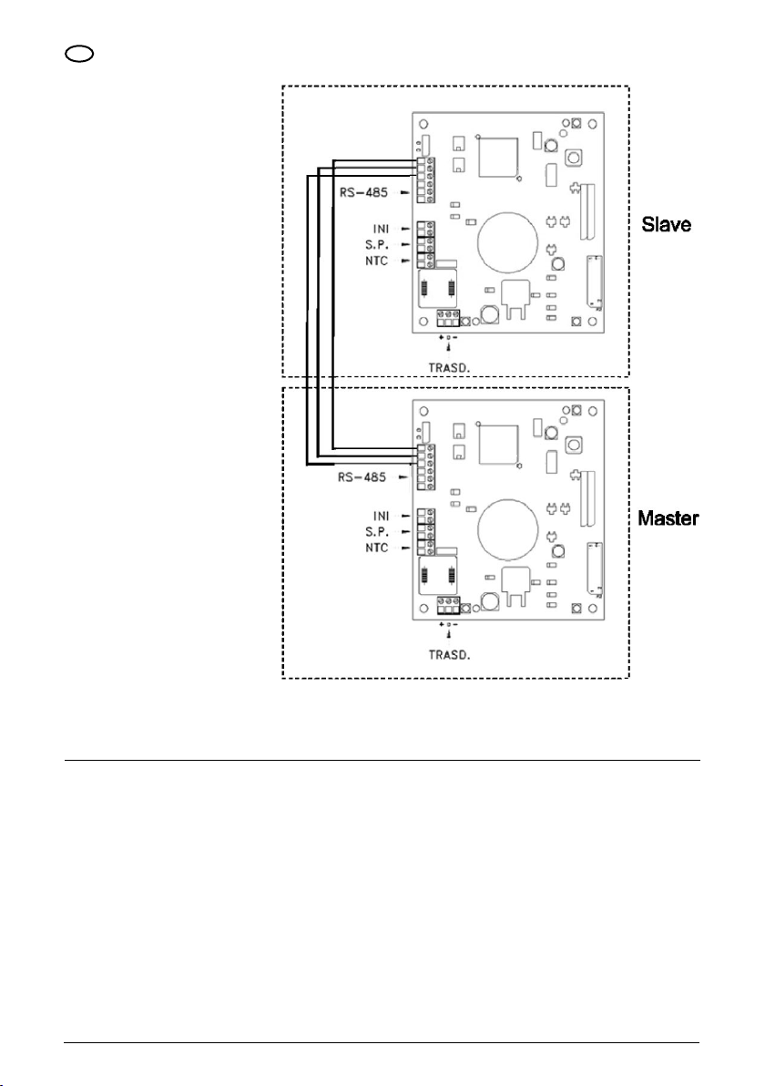
CPS controls for the unit, such as MASTER (PRI – P) and SLAVE (SEC – S), are automatically configured. Alternatively,
the "advanced parameters" can be used to configure the controls.
Settings for the master motor (PRI “P”) can be selected using the installation menu parameters.
Settings will be saved in case of a power failure.
For a correct configuration, we recommend using the installation parameter menu (Lev. 2) with the machine on STOP
and connected to the power supply.
NOTE
NOTE
NOTE
NOTE
The system has five settings:

28
CHaPter 5
PROGRAMMING
Press the START/STOP button to start and/or stop the pump
When running normally (that is, in the absence of any alarms) press the MODE button to alternate the various displays available:
5.1 CONTROL PANEL DESCRIPTION
5.2 DESCRIPTION OF SIGNALS ON DISPLAY
1. BAR/PSI - SYSTEM PRESSURE
2. HZ - MOTOR FREqUENCY
• Current pressure, shown in large
numbers on the display
• Currently active set point (set 1 or
set 2), shown in small numbers on
the display
• Current frequency of the pump in Hz
• Pressure unit of measurement
(bar or PSI)
• Frequency graph indicator
• Day of the week
• Master (P) or Slave (S), only for unit
configuration
• Day of the week
GB
The control panel is shown in picture below.
• Indication: Day/Hour/Pressure/
Alarms/Faults/Advanced parameters
Frequency/Current/State of the pump.
• Indication of access to settings.
• Unit of measure of the displayed
parameter.
• Temperature alarm indication.
• Address module (Primary/Secondary).
• START/STOP/Reset key.
• Key to confirm the changes made.
• Key for cancelling the changes made
during setup.
• Parameters change pushbuttons.
• Display change pushbutton.
• Control type display icon.
• Operation LED (green)
Alarm/Fault (red).
• Indication of displayed SET-POINT.
• Line LED green.
• Graphic display of the frequency
supplied to the motor.

29
The parameter displayed by default is pressure (BAR or PSI); after 10 minutes of displaying one of the other parameters the system
automatically returns to displaying pressure.
5.3 PROGRAMMING MENU
3. A - ABSORBED CURRENT
4. HH:MM - TIME
5. COMPLEMENTARY PUMP STATUS (UNIT ONLY)
• Current absorbed by the pump in
Ampere
• Time
• STB” the complementary pump is
on standby
• “ON “the complementary pump is on
and regulating
• Frequency graph indicator
• Day of the week
• “TOP” the complementary pump is
on and is at the maximum possible
frequency
• Day of the week
• Frequency graph indicator
• < Alarm Code > the complementary
pump is in alarm (for a description of
alarm codes, please see Chpt. 6.0)
For a correct configuration, we recommend using the "installation" and "advanced" parameters with the machine on
STOP and connected to the power supply.
NOTE
MENU DESCRIPTION
TIME/DAY To enter the time and day of the week.
SET-POINT To change the system pressure SET-POINT.
ADVANCED PARAMETERS (LEV.1) To change setting parameters.
INSTALLATION PARAMETERS (LEV.2) To change system setting parameters.
Functioning of the module is programmable using a series of parameters grouped into 4 sub-menus:
GB
The CPS module indicates with the symbol the modification status of the parameter.
NOTE
Press the SET button to save the set parameters and exit the programming mode.
NOTE
Press ESC to exit the programming mode without saving any of the changed parameters.
NOTE

30
5.3.1 PROGRAMMING CLOCK/DAY
During the first installation phase, the module display flashes to indicate the internal clock needs updating.
The clock is equipped with a battery to maintain the time and date for 24 hours if there is no power.
NOTE
NOTE
MENU DESCR
DISPLAY
PARAMETER
NAME DESCRIPTION DEF MIN MAX
PROG. TIME ORA Time Time on system 00:00 00:00 23:59
GIO Day of week Day of week MO MO SU
To modify the time, repeatedly press the “MODE” button until you arrive to the time parameter.
5.3.2 SET POINT
Press the MODE button to go from SET1 (Set-point1) to SET2 (Set-point2).
NOTE
MENU DESCR
DISPLAY
PARAMETER
NAME DESCRIPTION DEF
(bar)
MIN
(bar)
MAX
(bar)
SET POINT
SET 1 Set Point 1 Main pressure value 3 1 8
SET 2 Set Point 2 Secondary pressure value
(can be set only if the parameter SET n = 2) 2 1 8
To access this menu press and release the SET button:
• Press the “SET” button to enter the
menu to change the date and hour
• During the modification of the
parameters, the symbol on the
display lights up
• With the buttons it is possible to
modify the time
• Press MODE to move onto changing
the day
• With the buttons it is possible to
modify the day
• To save the values press “SET”. The
symbol will disappear and the
words “REC” will appear on the
screen for a few seconds to show that
the data has been saved
• Press “MODE” to go back to the
pressure screen
• During the modification of the set
point parameters, the symbol
lights up on the display
• With the buttons it is possible to
modify the pressure values
• SET POINT 1: Pressure desired by
the system, the module varies the
motor speed to maintain the system
pressure as near as possible to the
set one. During the regulation of this
parameter, "SET 1" appears
• SET POINT 2: Present only if the
module was set to function with two
set points (SETn = 2”, see “ADVANCED
PARAMETERS”). When setting this
parameter the display shows SET1
followed by SET2, proceed to program
Pres "SET" to confirm. The symbol will disappear. The words “REC” will appear on the screen for a few seconds to show that
the data has been saved. If two SET POINTS are present, it is possible to select the one desired using the “S.P.” external contact
(see electrical connections diagram) or the internal clock (see Chapter 5.3).
GB

31
5.3.3 ADVANCED PARAMETERS
Key sequence to access the advanced menu, button pressed for 10 seconds
MENU DESCR.
DISPLAY
PARAMETER
NAME DESCRIPTION DEF MIN MAX
PARAMETRI AVANZATI
TPR E Unit of measurement. Pressure unit of measurement. BAR BAR PSI
SET N Number of SET POINTS. Number of set points used. 1 1 2
ROT Motor rotation direction.* Motor rotation direction. POS POS NEG
COR Nominal current.* Pump nominal current (read on plate: In). In 1 8
INI Outside contact setting. Type of inhibitor signal, n.a. (normally open) or n.c. (normally closed). NO NO NC
* Manufacturer's setting.
GB

32
5.3.4 INSTALLATION PARAMETERS
GB
Key sequence to access the installation menu, last button pressed for 10 seconds.
MENU DESCR.
DISPLAY
PARAMETER
NAME DESCRIPTION DEF MIN MAX
INSTALLATION
PARAMETERS
TIP O Pump type
Identifies whether the pump is part of a unit or whether it
is a single pump, possible values:
• NCON: pump not configured (factory setting)
• SING: single pump
• PRI: primary or master pump for a unit
• SEC: secondary or slave pump for a unit
SING N.A. N.A.
SCA Type of exchange
This parameter indicates the mode used to change pumps
when the pump is part of a unit (PRI, SEC).
• CH01: Indicates that the first pump to come on at the next request for water
will be the one which started-up second or which did not start-up during the
last cycle. The second pump cannot support the first in this mode
(BOOSTER setting).
• CH02: Indicates that the first pump to come on at the next request for water
will be the one which did not start up during the last cycle. The second pump
cannot support the first in this mode.
• CH03: Indicates that the first pump to come on at the next request for water
will be the one which has run for the least amount of time (see functioning
hours parameter). The second pump cannot support the first in this mode
(BOOSTER setting).
• CH04: Indicates that the first pump to come on at the next request for water
will be the one which has run for the least amount of time (see functioning
hours parameter). The second pump cannot support the first in this mode.
• CH05: In this setting, the first pump to start-up is the one entered as the
primary pump in the "type of pump" parameter. The second pump can
support the first in this mode; however, the cyclical function is not available.
01 01 05
INF F Minimum frequency Parameter defining minimum motor rotation frequency. 30 20 40
SUP F Maximum frequency Parameter defining maximum motor rotation frequency. 50 40 60
ANP F Reactivity factor Parameter defining the speed with which the motor responds to changes in
pressure. The lower the setting the faster the motor's response. 15 1 50
SUP S Bottom scale sensor Parameter defining the sensor at the bottom of the scale (in bar). 10 2 30
INF S Zero sensor Minimum value read by the sensor (zero). 0,6 0 1
OFF P Offset sensor Use to enter an offset value for the pressure sensor. 0 0 10,0
SPE T Switching off time
Interval of time during which pressure must remain stable (+/- 0.1 Bar) with a
rotation lower than the average switching off frequency + 10 to trigger the motor
shutdown cycle (seconds).
10 3 50
• During the modification of the
parameters, the symbol on the
display lights up
• Use the MODE key to change various
parameters
• With the buttons it is possible to
modify the values
• To memorize the values press the
button “SET”. The symbol .
The words “REC” will appear on the
screen for a few seconds to show that
the data has been saved

33
5.4 MANUAL START OF MOTOR/PRIMING
GB
MENÚ DESCR.
DISPLAY
NOME
PARAMETRO DESCRIZIONE DEF MIN MAX
INSTALLATION
PARAMETERS
DIF P Pressure threshold
Subtract this figure from the set point to obtain pressure when the motor is
started-up. In other words, the motor starts-up when pressure reaches the set
point value minus the threshold value (BAR).
0,3 0,1 0,5
ALL P Water alarm pressure Indicates minimum system pressure, a lack of water alarm will be generated
under this threshold value Set to zero to disable this function. 0,5 0 1
RIP 1 1st start-up
Waiting time between the first lack of water reading and first attempt to
automatically restart the system (minutes). The module will not attempt to
restart if this parameter is set to zero.
1 0 1440
RIP 2 2nd restart Waiting time between the first restart and the second attempt to automatically
restart the system (minutes). 5 0 1440
RIP 3 3rd restart Waiting time between the second restart and the third attempt to automatically
restart the system (minutes). 60 0 1440
RIP 4 4th restart Waiting time between the third restart and the fourth attempt to automatically
restart the system (minutes). 720 0 1440
RIP F Restart type
Parameter used to define how the restarting mechanism works. If set to FIN,
the module will go into a definitive alarm after the fourth attempt. If sent to
CICL, it will attempt to restart indefinitely using the interval specified during the
fourth attempt.
FIN FIN CICL
RIP T Intervention time Waiting time after restarting within which pressure must return to above the
minimum threshold level for lack of water. (seconds) 15 5 300
ORE P Hours running Number of hours the pump has been running. N.A. N.A. N.A.
SCA T Exchange time
Parameter indicating the amount of time a pump must run for.
Once this value has been reached, the pump will stop and a second pump will
commence working. This parameter is expressed in minutes until it reaches 60,
after which it is expressed in hours. The difference is indicated by the presence
of an "H" for hours and an "M" for minutes.
Must be set to primary for a unit or for twin pumps.
0 0 168
SCA S Exchange time mode
Pumps are exchanged once the SCAT parameter has been reached:
T1: The active pump is switched off first, before the second pump starts up
T2: The second pump is switched off first, before the first pump starts-up.
1 1 2
FP PWM frequency Frequency of the PWM which controls the motor. 15,9 5.1 15,9
TAB Anti-locking
Amount of time the pump is inactive. Once this amount of time has expired, the
pump will start up for 15 seconds at maximum frequency. Then, the frequency will
be slowly lowered until the minimum set frequency is obtained. This parameter
is expressed in minutes until it reaches 60, after which it is expressed in hours.
The difference is indicated by the presence of an "H" for hours and an "M" for
minutes.
0 0 999
During manual start-up, the motor rotates at maximum speed and the pressure control is not activated, therefore the
pump reaches its maximum pressure.
Ensure there is water inside the pump unit, otherwise the pump seal will be destroyed.
ATTENTION
ATTENTION
Buttons sequence with pump off, last button pressed for 10 seconds.
This procedure is applicable when you want to manually start the system or prime the pump.
It is possible to manually start the motor by pressing the following sequence of buttons:

34
GB
5.5 MANUAL START/STOP
It is possible to manually stop the pump by pressing the START/STOP button: in this situation the display alternatively shows the
writing STOP. During STOP status the module is not operative unless the anti-lock mode is activated (TAB parameters - installation
parameters 5.3.4). The word "abl" will be displayed if the condition is active.
START/STOP sequence of buttons, push the STOP button
Press the START/STOP button again to exit the STOP condition.
ATTENTION
SIGNALS, ALARM STATUS AND ERRORS
CHaPter 6
6.1 HISTORY (SAVED)
MESS. DISPLAY DESCRIPTION ACTION
INIT System initiation signal. The condition occurs when the system is first
started-up or after a prolonged power failure. Wait for a change in status.
REIN System re-initiation signal. The condition occurs when a short power failure
takes place.
INIB Inhibitor intervention signal.
This is an operative condition generated by an
external command which closes entry to the
inhibitors. (NO – NC)
Check the external inhibitor command
(i.e. switch, float, pressure gauge).
RPC Reset configuration.
REC Saving parameter signal.
RST Total reset signal.
The board has been reset. The cause of this signal can be a either
prolonged absence of power or if the reset button has been pressed
manually. The module will save all the information recorded, with
the exception of clock setting.
RSE Memory reset. The eeprom memory has been reset (see chapter 7.2). The module
returns to the factory settings.
ESG Memory reset carried out. Confirms that the eeprom memory has been reset (see chapter 7.2).
FAL End of alarm (in memory). Indicates the end of an alarm.
TOP Maximum power complementary pump. The complementary pump is on at the maximum frequency possible.
ON Complementary pump on. The complementary pump is on and regulating.
STB Complementary pump on standby. The complementary pump is on standby.
6.2 SIGNAL TABLE
Key sequence:
Press ESC for 5 seconds.
Press MODE to scroll the error log.
Press STOP to see the hour and the date of the event (when the clock has been set correctly).

35
GB
6.3 ALARM TABLE
MESS. DISPLAY DESCRIPTION ACTION
A01 No water alarm - temporary
Error due to the temporary absence of water. This occurs
when water is absent and the restart mechanism has been
activated. The will wait before restarting in order to attempt
to automatically reset the error.
Check the water level in the first tank or the aqueduct pressure.
Wait for the programmed attempted restart or press the button
START/STOP for a manual restart.
A02 No water alarm - definitive
This condition occurs when there is no water and the
automatic restart system has not activated or restart
attempts occurred already without managing to reset the
system functioning.
This alarm condition closes the J3 contact on the power
board for possible external signals (alarm light, siren, etc.)
Check the water level in the first tank or the aqueduct pressure.
Press the button START/STOP to manually restart the system.
A03 Pressure transducer alarm. This signal occurs when the control board cannot identify
the transducer pressure signal.
Check the pressure transducer is correctly connected.
If the error occurs again, contact your nearest assistance centre.
MESS. DISPLAY DESCRIPTION ACTION
E00 No event. The error log appears when no errors have been signalled.
E01 Fault generico.
(segnalazione memoria)
This error occurs in the presence of:
• Internal module error
• Overheating of the power module
• Pump failure
Press the START/STOP button to attempt to exit this condition. In
case of a persistent error, contact technical support.
E02 Temporary external error.
An external error occurs when there is a problem with the
power module. The module will not be operative during an
EXTERNAL ERROR.
In this case, the module will attempt to restart normal functioning
after 5 minutes and will repeat this procedure up to five times.
Press the START/STOP button to attempt to exit these conditions.
Please contact technical support of the error persists.
E03 Definitive external error. The definitive external error condition is indicated after the
temporary error condition is repeated 5 times.
Press the START/STOP button to attempt to exit this condition.
Please contact technical support of the error persists.
E04 Communication error.
This error condition occurs when the control board cannot
communication with the power part. This alarm condition
closes the J3 contact on the power board for possible
external signals (alarm light, siren, etc.).
Cut the power off and wait until the LINE Led switches off and
after which turn power back on. If the error condition occurs again,
contact your nearest assistance centre.
E05 Over voltage error.
This error occurs when the current absorbed by the module
is greater than triple the nominal current.
This condition can be caused when the pump is blocked
by foreign bodies.
This alarm condition closes the J3 contact on the power
board for possible external signals (alarm light, siren, etc.)
Cut off the power supply and wait for the LINE Led to switch off.
Check the pump freely rotates and if necessary remove foreign
bodies that block correct functioning.
Turn power back on.
If the error persists, contact your nearest assistance centre.
E06 Under voltage error
temporary.
This error condition occurs when the voltage is 10% less
than the nominal voltage (230V).
This alarm condition closes the J3 contact on the power
board for possible external signals (alarm light, siren, etc.)
Press the button START/STOP or cut the power off and wait until the
LINE Led switches off and after which restart the system.
If the error occurs again, contact your nearest assistance centre.
E07 Under voltage error
definitive.
This error occurs when the temporary under voltage
condition is repeated 5 times.
6.4 ERROR TABLE

36
GB
E08 Over voltage error
temporary.
This error condition occurs when the voltage exceeds by
10% the nominal voltage (230V).
This alarm condition closes the J3 contact on the power
board for possible external signals (alarm light, siren, etc.)
In this case, the module will attempt to restart normal functioning
after 1 minute and will repeat the procedure up to five times. Press
the button START/STOP or cut the power off and wait until the LINE
Led switches off and after which restart the system.
If the error occurs again, contact customer care.
E09 Over voltage error
definitive.
A definitive over voltage error occurs after a temporary over
voltage error is repeated 5 times.
E10 Absence of network power
(in memory) This condition occurs following a network absence.
E11 Power error. This condition indicates a motor power absorption error in
terms of its running status.
Press the START/STOP button or cut off power and wait until the red
Led LINE goes off, then power again to reset the system.
If the error occurs again, contact your nearest customer care centre.
E12 Memory error. This error occurs when eeprom is unable to load the
parameters which have been entered.
Wait for a few minutes. If the signal remains, press the button
START/STOP or cut the power off and wait until the LINE Led
switches off and after which restart the system.
E13 Configuration error.
This error occurs when the control board cannot correctly
communicate with the power part. This alarm condition
closes the J3 contact on the power board for possible
external signals (alarm light, siren, etc.).
Press the button START/STOP or cut the power off and wait until the
LINE Led switches off and after which restart the system.
If the error occurs again, contact your nearest assistance centre.
E99 Undefined error. This error occurs when an unforeseen error takes place. Wait for a few minutes. If the signal remains, contact your nearest
customer care centre.
485E Communication error. This signal refers to pump units and is indicated when the
devices are not communicating correctly.
Press the button START/STOP or cut the power off and wait until the
LINE Led switches off and after which restart the system.
Check the communication cable. If the error occurs again, contact
your nearest customer care centre.
MESS. DISPLAY DESCRIPTION ACTION
RESETTING AND FACTORY SETTINGS
CHaPter 7
7.1 GENERAL SYSTEM RESET
Press only as a last resort to restart the system.
ATTENTION
Triggers a general module reset and reloads set values saved in eeprom. Press as a last resort only in order to restart the module.
If, for whatever reason, the module becomes blocked, wait approximately 10 seconds for the module itself to automatically launch a
general reset. If this does not reset the system, use this key and contact a customer care centre.
Reset key sequence, press SET for 20 seconds.

37
GB
7.2 TO RESET FACTORY SETTINGS
Loads all default values and deletes all previous values entered.
ATTENTION
The factory values can be loaded by pressing a sequence of keys.
TABLES AND DESIGNS
CHaPter 8
8.1 DATA PLATE
Key sequence to reset setting, press DOWN, ESC, ARROW DOWN, ESC, ARROW DOWN, ESC, press for 10 seconds.
Press SET to confirm reset.
7.3 SOFTWARE VERSION
Key sequence to see the software version, ARROW UP for 5 seconds.
1) Type of motor pump
2) Maximum flow rate l/min
3) Nominal power (P2)
4) Maximum temperature of liquid
5) Nominal current
6) Maximum head in metres
7) Insulation class and level of
protection
8) Absorbed current
9) Date and year of production
10) Frequency
11) Software version
12) Power voltage
13) Number of phases
14) Absorbed power (P1)

38
GB
8.2 INSTALLATION OF THE NEGATIVE SUCTION HEAD
1) Basin or tank
2) Float
3) Shut-off valve
4) Outlet tubing
5) Tank/autoclave membrane (8 l/min)
6) Gauge
7) Pressure transducer
8) Flexible tube
9) Non return valve
10) Filter
11) Motor pump complete with inverter

39
GB
8.3 INSTALLATION OF THE POSITIVE SUCTION HEAD
For the installation of the positive suction head, ensure the correct inclination of the suction piping until the air present in the
tubing can exit the outlet tubing.
1) Basin or tank
2) Float
3) Shut-off valve
4) Outlet tubing
5) Tank/autoclave membrane (8 l/min)
6) Gauge
7) Pressure transducer
8) Flexible tube
9) Non return valve
10) Filter
11) Motor pump complete with inverter
This manual suits for next models
1
Table of contents
Popular Media Converter manuals by other brands

M2TECH
M2TECH JOPLIN user manual

B&B Electronics
B&B Electronics RS-232 Baud Rate Converter CE 232BRC product manual

PRO SIGNAL
PRO SIGNAL PSG3371 user manual

M-system
M-system M8XV2 instruction manual

Wellav
Wellav UMH160UIG user guide

Transition Networks
Transition Networks SISTG10 211-LR Series installation manual