INSTALLATION
If your loco has an NMRA DCC socket, all you need to do is plug in the decoder.
However, it is quite a challenge to install a decoder into a locomotive without the DCC
socket. You should have some basic electrical knowledge and soldering skills. If you do
not have the above requirements, please ask the dealer for help in installation.
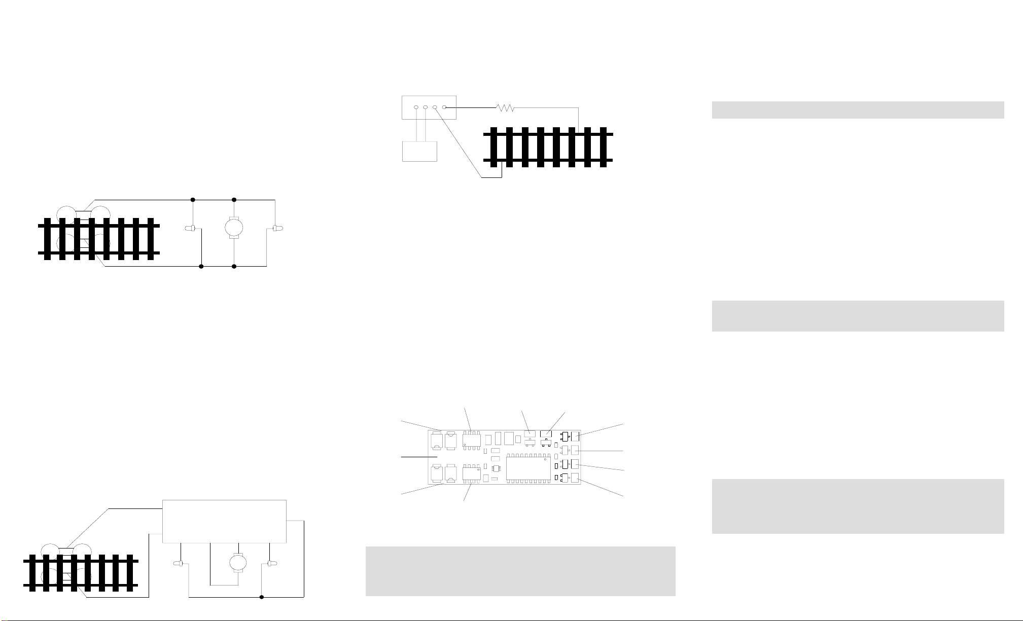
Figure 1 shows the electrical circuit of most standard locomotives. The terminals of
the motor and lights are directly connected to the wheel pickups. Each type of loco
has its own method of electrical pickup. The connection between wheel and motor/
light could be wires, clips, the body or any conductor. Figure out your locomotive’s
electrical connection and how to disconnect (isolate) the motor and lights. The de-
coder will be inserted between the wheel pickups and the motor. The ‘X’ marks in
Figure 1 show you where to disconnect.
Figure 1. Connection of a standard loco Note: The ‘X’ signs indicate where to
disconnect (isolate)
Figure 2 shows you how to wire the decoder. After disconnecting the motor termi-
nals from pickups, connect the red wire to the right side pickup and the black wire to
the left side pick up. Connect the orange wire to the motor terminal that originally
connect to the right pickup. Connect the gray wire to the motor’s other terminal.
Connect the front light to the blue wire and the white wire. Connect the rear light to
the blue wire and the yellow wire.
The blue wire is the common terminal for lights and accessory functions. You may
use the black wire or the red wire to replace the blue wire. This is very useful when
you find that it is hard to isolate one of the light terminals from the pickup. Wiring the
bulb this way will also make the light dimmer. If your loco has only a front light, you
should connect the white and the yellow wires together.
Solder tabs are furnished on the AD350 decoder for accessory functions F1, F2, F3
and F4. If you wish to use these functions, you can solder wire to these tabs using
the supplied accessory wires. Use a small wattage soldering Iron in conjunction with
electronic soldering paste. To avoid any damage on the decoder do not solder one
tab more than 5 seconds at a time. If you need more time to solder, please let it cool
down before soldering again.
Figure 2. Decoder wiring diagram
TEST
All MRC decoders have been factory programmed with address #3, 28/128 speed
steps and maximum top voltage.After you have finished your decoder installation, you
are ready to test it. Never run the installed decoder on your layout without first
passing the test. You may damage the decoder if it is not wired correctly or if you
have not properly isolated the motor and the lights.
Put the loco on the test track. Select the Run Mode of your DCC system and select or
acquire address #3. Move up throttle and the loco should move forward. Push the light
button and the front light of your loco should turn on. Push the reverse direction but-
ton. The loco should move backward and the rear light should turn on.The loco cannot
get to normal speed because there is a 20 ohm protection resistor in the test track. If
you are able to turn on/off the front and rear lights and you are able to move the loco
in forward and reverse, you did a great job. Congratulations! Do not test the loco on
the test track for an extended period of time. To do so will cause the protection
resistor to overheat.
MAKE A TEST TRACK
Before you start with your decoder installation, we strongly recommend building a test
track which uses a 20 ohm resistor to limit current. Only test your installed decoder
on the test track. The test track will prevent any damage due to an incorrectly wired
decoder.
Figure 3. Diagram of test track
OPERATION
The AD350 decoder can be operated in either one of two ways:
1. Normal light/functions:
Headlights are directional, and controlled by your DCC system’s F0
button. Decoder function output solder tabs (1, 2, 3 & 4) are normal on/
off, controlled by F1-F4 buttons.
2. MRC Light Effects:
All MRC Light Effects have adjustable flash rates.
A. “Rule 17” directional headlights: Headlights on/off, (F0). One light is
bright to indicate direction of travel, the other is dim.
B. Ditch lights: Using decoder function output solder tabs 1 and 2 plus
decoder blue common wire.
F1,F5 button: Pressing F5 button once or double clicking F1 button
turns ditch lights steady on or off, still giving you
independent operation of F1 function such as bell
sound.
F2 button: Using function button F2, ditch lights will flash fifteen
(15) times.
F3 button: Using function button F3, the ditch lights will flash
ten (10) times.
C. Strobe light: Decoder function output solder tab 3 plus decoder blue
common wire.
D. Mars light: Decoder function output solder tab 4 plus decoder blue
common wire.
The above two MRC Light Effects (C & D) can be used separately
or together and are controlled by function button F4.
HOW TO SELECT THE MRC LIGHT EFFECTS
The AD350 is shipped from the factory in the normal/default mode (address #3)
normal lights & functions. There are two ways to access the MRC Light Effects:
1. The MRC EZ way (for all DCC systems except the MRC Command 2000):
Place your locomotive on a programming track. Program your locomotive
to address #1. To adjust the flash rates while in the programming mode,
program in a momentum/acceleration rate (CV#3). This step turns our
MRC Light Effects on. Final step: Now program in your locomotive
running address, either 2 or 4-digit, and adjust the rest of your running
parameters (momentum, start voltage, etc.). That’s it! To turn off the
MRC Light Effects, simply program the locomotive to address #3 and
then follow the final step above.
You cannot run a locomotive on address #1 and retain normal lights/
function or run a locomotive on address #3 with MRC Light Effects.
These two addresses are reserved for turning the functions on and
off, but a locomotive will still be able to run on these addresses.
2. The other way:
If your non-MRC DCC system has the ability to program CVs, you can go
directly to the CVs to custom tailor your MRC Light Effects. Your can use
the register/CV chart we have provided for you in this instruction booklet
or visit the National Model Railroad Association website at www.nmra.org
for a more comprehensive understanding of CVs and registers.
If your installed decoder does not pass the test, find the problem, correct it and
test it again.As long as you test the decoder on the test track there is little chance
of damaging your decoder. This is why making a test track is so important.
X X
X X X
X
Right side pickup
Front
light Motor Rear
light
Left side pickup
Front
light Rear
light
Red
OrangeGray
White
Black Yellow
AD350 Decoder
Motor
Blue
DCC base unit
Power supply
Test track
20 ohm resistor
Red wire
Black wire
Blue wire
Yellow wireWhite wireOrange wire
Gray wire
Output 1
solder tab
Output 2
solder tab
Output 3
solder tab
Output 4
solder tab
AD350 wiring diagram


