manuals.online logo
Brands
  1. Home
  2. •
  3. Brands
  4. •
  5. Pentax
  6. •
  7. Digital Camera
  8. •
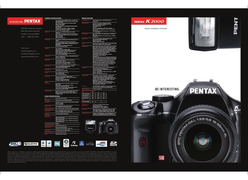
  9. Pentax MZ-5 User manual

Pentax MZ-5 User manual

This manual suits for next models

6

Other Pentax Digital Camera manuals

Pentax PZ-1 User manual

Pentax

Pentax PZ-1 User manual

Pentax KM User manual

Pentax

Pentax KM User manual

Pentax PC-330 DATE User manual

Pentax

Pentax PC-330 DATE User manual

Pentax MZ-S User manual

Pentax

Pentax MZ-S User manual

Pentax Optio A10 Instruction manual

Pentax

Pentax Optio A10 Instruction manual

Pentax MZ-60 User manual

Pentax

Pentax MZ-60 User manual

Pentax P3 User manual

Pentax

Pentax P3 User manual

Pentax OPTIO S4 User manual

Pentax

Pentax OPTIO S4 User manual

Pentax PZ-20 Instruction Manual

Pentax

Pentax PZ-20 Instruction Manual

Pentax Data MX User manual

Pentax

Pentax Data MX User manual

Pentax Optio 50L Assembly instructions

Pentax

Pentax Optio 50L Assembly instructions

Pentax K-X User manual

Pentax

Pentax K-X User manual

Pentax Mini Sport 35AF User manual

Pentax

Pentax Mini Sport 35AF User manual

Pentax Optio S5z User manual

Pentax

Pentax Optio S5z User manual

Pentax Optio E90 Red User manual

Pentax

Pentax Optio E90 Red User manual

Pentax K-r User manual

Pentax

Pentax K-r User manual

Pentax Optio RZ10 User manual

Pentax

Pentax Optio RZ10 User manual

Pentax Optiio550 User manual

Pentax

Pentax Optiio550 User manual

Pentax EI-200 User manual

Pentax

Pentax EI-200 User manual

Pentax K-r User manual

Pentax

Pentax K-r User manual

Pentax 17116 - Optio M50 8MP Digital Camera User manual

Pentax

Pentax 17116 - Optio M50 8MP Digital Camera User manual

Pentax IQZoom 130M User manual

Pentax

Pentax IQZoom 130M User manual

Pentax ZX-M User manual

Pentax

Pentax ZX-M User manual

Pentax S45 Instruction manual

Pentax

Pentax S45 Instruction manual

Popular Digital Camera manuals by other brands

Canon WP-DC35 user guide

Canon

Canon WP-DC35 user guide

Xiaomi 70mai Dash Cam Lite user manual

Xiaomi

Xiaomi 70mai Dash Cam Lite user manual

Samsung PL70 Quick start manual

Samsung

Samsung PL70 Quick start manual

GE E1680W user manual

GE

GE E1680W user manual

Canon EOS 1200D instruction manual

Canon

Canon EOS 1200D instruction manual

Tevion MD 86497 user guide

Tevion

Tevion MD 86497 user guide

Exakta VX Features

Exakta

Exakta VX Features

Kodak Digital Science DC120 user guide

Kodak

Kodak Digital Science DC120 user guide

Nikon FM3A Specifications

Nikon

Nikon FM3A Specifications

Vectra Fitness H1 Quick reference guide

Vectra Fitness

Vectra Fitness H1 Quick reference guide

Nikon COOLPIX 775 quick start guide

Nikon

Nikon COOLPIX 775 quick start guide

Olympus IR 500 - 4MP Digital Solutions Camera Manuel de Référence

Olympus

Olympus IR 500 - 4MP Digital Solutions Camera Manuel de Référence

Samsung EC-L100ZBBA brochure

Samsung

Samsung EC-L100ZBBA brochure

FujiFilm FINEPIX BL01124-201 owner's manual

FujiFilm

FujiFilm FINEPIX BL01124-201 owner's manual

Panasonic DMC-L10KPP Service manual

Panasonic

Panasonic DMC-L10KPP Service manual

Hyundai Electric HYU-CC-CHBF12001 Quick installation guide

Hyundai Electric

Hyundai Electric HYU-CC-CHBF12001 Quick installation guide

Sony DSC-WX80 specification

Sony

Sony DSC-WX80 specification

Nikon Nuvis S - Point & Shoot instruction manual

Nikon

Nikon Nuvis S - Point & Shoot instruction manual

manuals.online logo
manuals.online logoBrands
  • About & Mission
  • Contact us
  • Privacy Policy
  • Terms and Conditions

Copyright 2025 Manuals.Online. All Rights Reserved.

PENTAX
®
Service Manual
ENGLISH
PENTAX
AtZ·S~~~rz
..
PRODUCT
No.27250
M z-5
OUARTZ
DATE
(Silver)
PRODUCT
No.27251
M z-5
QUARTZ
DATE
(BI
ack)
PRODUCT
No.27254
Z
X-5
(Si Iver)
PRODUCT
No.27255
Z X - 5
QUARTZ
DATE
(Silver)
PRODUCT
No.27256
M
Z-5
(Si Iver)
.,,
[
TABLE
OF
CONTENTS
)
Page
Specifications · · · · · · · · · · · · • · · · · · · · 2
LCD
& Finder
indications
• • • • · · · · · · · · · · · 2
Disassembly
and
Assembly
procedure
L I External parts I · · · · · · · · · · · • ·
I
L_
Adjustment
and
confirmation
I
8-
1.
Function
check
{p.13)
3
I
I
I
I
8-2.
Adjustment
and
check
with
computer
program
(p.14)
8-3.
Exposure
value
and
DX
switching confirmation
{p.15)
8-4.
AF
and
PZ
confirmation
(p.16)
r--
7.1
Top
cover
I . . . . . . . . . . . .
I
2.
l Soldering
of
Main
unit I·
I
12
4
3.l
Main
unit
and
Front
housing
block
I· · · · · · · 5
I
r--
6.
I
Main
unit I · · · · · · · · · · ·
10
I
4.1
Main
P.C.board
I · · · · · · · · · · · · · 6
I
5. I Front
housing
block
. . . . . • . . . 7
L-
8-
6.
Mirror
function
check
(p.17)
8-
7.
1st
and
2nd
mirror
position
(p.17)
Adjustment
and
Confirmation
8-
1.
Function check · · · · · · · · · · · · · • ·
13
8-2.
Adjustment
and
check
with
computer
program
14
(Auto
exposure
and
Auto
focus)
8- 3. Photo sensor
position
· • · · • ·
8-
4.
Exposure
value
and
DX
switching
con.firmation
8-
5.
Auto
focus
and
Power
zoom
confirmation
15
16
16
8-
6.
Mirror
function
check
· · • . . .
17
8- 7.
1st
and
2nd
mirror
position
. • . •
17
Others
Mechanical
back
· · • · · · · · · · · · · • · 5
AF
joint stroke · · · • • • 9
Viewfinder
focus
and
Parallax
9
Program software
flow
chart
Table
of
testers, jigs
and
tools
Order list
of
testers,
jigs
and
tools
·
18
22
23
Method of
making
DC
power
adapter
(handmade
jig)
· • · · • 24
27250
l/24
Type:
Format:
Usable Film:
Exposure Mode:
Shutter:
Lens
Mount
:
Competible Lens:
Autofocus
System:
·
Power
Zoom:
Viewfinder:
Viewfinder Indication:
Extomal
LCD
panal
lndlcetion:
Self·timer:
Mirror:
Fiim Loading:
Film Wind & Rewind:
Exposure
Meter:
[
SPECIFICATIONS
]
TTL
autofocus. auto-exposure 35mm SLR with built·
in
TTL
auto n
..
h (RTF)
24x36mm (Approx.
13x36
in
panoramic format)
35mm parforated cartridge
film.
DX·codtd
film
with
ISO
25-5000; non-DX
coded
films with ISO 6·
6400
Programmed
AE
Mode. Shutter-Priority
AE
Mode. Aperture-Priority
AE
Mode. Metered Manuel Mode.
Bulb
Mode
Electronically controlled vertical-run focal·plane shutter. Electromagnetic release. Speed range:( 1)Auto
1
/2000-30
soc.(stepless).(2)Manual I
/2000·2
nc.(3)Bulb.
Shutter lock by setting Drive mode switch
et
L
Pentu
K..1
bayonet mount(K-mount with
AF
coupler. lens infonNtion
contacts
and power
cont1cts)
Ptntu
K...r.
l(.,
••
K
•••
and K-mount lenses
art
usable. Autofocus is pos.sible using
AF
Adapter with K·K.-
mount len11s.
TTL
pha11·m11ching 3 point autofocus system switchable
to
Spot focusing,
AF
operational brightness
range: EV·l
to
lB(at
ISO
100
with f
/1.
4 lens). Focus lock av1ilable using
shutter
release button. Focus
Mode: AF(predictive
AF
provided), M1nu1l(
MF]
3·Speed Intelligent Power Zoom lens with bullt·in motor with
FA
zo
om
lens
Ptntaprism finder. Natural-Bright-Matte focusing scr11n. F',.ld of viow
!929'.
Magnification:O.BOX(with
50mm lens
at
co),
Diopter: ·2.5 to +1.5 diopters. Panorama format frame
Focus lnformation:ln-focus (Green lamp (OJ
Is
lit). front or back focus signals and unable·to-focus indica·
tor (Green lamp blinks), Shutter speed indication, Aperture indie1tion, Flash reedy Indication (
~
)
Is
lit.
Bar
graph(uposure
compensation).Over or Under
uposure
indication in Manual Exposure Mode. (
gi
) expo·
sure
compensetion indication
(
P)
•Progremmed·AE
Mode. [
Tv]
•Shutter-Priority
AE
Mode.
(Av)
~Aperture·Priority
AE
Mode. [ M J
•Metered
Menual Mode.
(bu]
•Bulb-Mode,
Film
speed•
6.
6400.
ISO indication. (
<:l--l
•Film
status
inform1tion, (
Cll
) s B1ttery exhaustion warning, Fam
counter~0-99
(
~
):Built
-
in
fl.sh
ready indication
(
~
) •blinking slowly flash recommendad w1ming (
~
) •
bf"inks
rapidly Inappropriate lens warning, (
<I>
)
a
Red
.,
tye
reduction flash mode [
El
)•Au1om1ie
flash function, [
...
J~PCV
signal indicotion
ElectronieaUy.controlled type with delay time of 12 sec. St1rt by depressing of shutter ra
laast
button.
Opetation confirmation:
By
audible
PCV
signals. Cancelable 1fter operation
Instant-return mirror with
AF
secondary mirror
Film
advances automaticahy to 1st frame after beck cover is closed.
Film
information window is provided
Auto
wind/
rewind
by
built·in motor. Consecutive or Single advance mode. Approx.2.0
framu/sec.(consocutivo
mode),
Auto rewinding starts
at
end
of
roll.
Film
rewind/completion
of rewind·
ing
is displayed
on
the
LCD
panel. mid·roll rewind button
will
rewind
film
in
mid·rolt
TTL
multi(6)-segmont metering. Metering range from
EVO
to
EV2
1
at
150100
with SOmm
f/1.4
lens.
Canter-weighted and Spot metering mode can ba
Ht
Exposure
Compensation
:
+/·
3EV
in 0.5EV
step
increments
Flash : Sorias-control. Retr1ctable
TTL
Auto Flash (RTF). Guide
numb.:11
(IS0100/m).
lnumlnation 1ngle cov·
ors
28'MI
lens angle of
mw,
Flash-sync-speed
in
the range from
1/100
to a slower speed. Day.light-sync
flash. Slow·speed·sync flash. Contrast·control·synch flash (ISO range•
25-400
).
Automatic
fluh
function.
Rod·eyo reduction flash
Flash
•ync:
Power
Source:
Hot shoe with X-contact with coupled with Pentex dedicated 1uto flashes.
ISO
range•
25
-
BOO
Two
3V
lithium battery (CR2 or equivalent)
Battery
Exhaustion Battery exhaustion symbol (
Cll
] is lit (blinking when tho shutter is locked; no indication
on
the right·hand
Werning: edge of the viewfinder.)
Dimenslo.n
and
Weight: 135.0mm(W)x90.0mm(H)x61.5mm(D) (S.3"x3.S-x2.4") 400g(14.1 oz) body only without batteries
Supplied Accessories: Hot Shoa Cover
Fe.
Release Sockot Cap
F.
Camara Strap F
..
Eye
Cup
f.,
Finder Cap
Bock
cover:
In
terchangeable for replacing with Data Back
Fe
[
LCD
AND
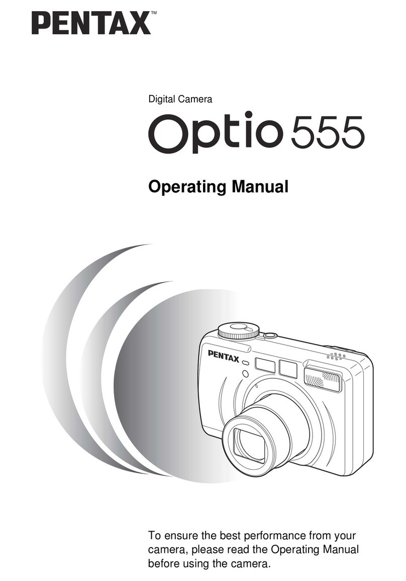
FINDER
INDICATIONS
J
• Finder indications
•
LCD
panel
indications
int
AF
frame
Finder
LCD
,
1.
External
parts
1- 1. Back cover and Bottom cover assy.
A201 (Back cover)
7 screws
Open the battery cover
...
-
....
,,
.......
·-
A401
(Bottom cover)
O
-
A4l~---~
O-A412 (Battery cover assy.)
1-2
.
Top
cover assy.
• 8 screws
A1
88
• Lift the top coverfrom the body, and then discharge
electricity
of
the
main capacitor with a
100-
lk
ohm
resistor.
..
· fig.
<D
TY-CNL·Dl.7X6.5
Unsolde.ring
(0-
Q201 +
QlOO)
4 lead wires
...
fig.
®
(0-TlOO + T51) 6 lands ..·
fig.
@
(A330 ) 1 black lead wire
..
·
fig.
@
0- A301
(fop
cover assy.)
Xe+
(blue)
Retainer screw (GND)
[ Note
of
assembly ]
_a/
/"TY
-CNL-01 .7X6.S(NI) ,
\(inside the
batt
chamber) A
184
Brown .
(QlOO)
• [ AdYConfirmation ] Photo sensor position (p.15)
Clean
every
connecting lands (0-TlOO, O-A301) before installing.
6 lands
Arrange
the
lead wires
and
1lex
ible boards as shown
in
the diagram
right.r.===
==
::;'tii)~1f}'}4
• Arrange T51 and the black lead
wire
from A330 on the slope of
1..3.
Arrange
the
4 lead wires
(QlOO)
between
0-
Q201
and 0-TlOO.
Make sure that
the
contact brushes
(fv,
Av)
are not damaged,
and make
sure
that the height of
the
brushes should be 4.3
mm.
1-3.
Front
covers
• 5 screws
A185
Al53 (Body covering, left)
A7 (Rewind
SW)
AIBB
• O-
Al02
(Front cover assy.)
•
Al03
(Cover frame)
Al50
(Grip)
[ Note
of
assembly ] l
"f!
-CNL-01.7X4.5
·
Set
both Body and
0-A102
with the
AF-po
sition. '(discontinued)
· A35
(Batt
contact piece)
and
A36
(Batt
cover
SW
...) should not project
over
the
battery chamber as shown in the diagram
right
[ Adj/Confirmation ] Function check
(p.13)-
Adjustment with computer program
(p.14)-
O.Smm <
-Exposure value and
DX
switching confirmation
(p.16)-
AF·PZ check
(p
.
16)
2.
Main
unit
and
soldering
[ Note of Disassembly and Assembly ]
• Turn the Panorama lever to normal frame.
2-1.
Unsolder the lead wires and lands as
shown
in
the fig.(
CD
,® ,@ ,@ )
• Remove the flexible boards from the
positionning studs.
[ Note
of
assembly ]
•
Set
the LCD frame plate underneath
the
LCD
to
the positionning hole of
the Front housing.
Arrange lead wires. •·· fig. (D
Put
on PT(lx7) and PT(l0x8).
...
fig.@
2-2.
2 screws
..
• fig. @
0-
M301
(Eyepiece assy.), M311 ®
2-3.
A307 (Spot
AF
switch)
A34,(Cusion)
x2
..• fig.
<J)
4124
TY-CNL-Gl.7x3.0
TY-CNL-DL7x3.5(Ni)
TY-CNL-Dl.7x4.0
(N300)
A33
27250
TY
·CNMl.7X4.
5.
O-M301+M311
7 lands
(DX)
-
3.
Main
unit
and
Front
housing
blo
ck
3-
1.
Remove
6 screws.
Al62
(Reinforced
plate)
Peel
off
two
PT(lxl5)s
on
the bott
om.
3-
2.
Re
mov
e the Front housing
from
the
main
unit
with
paying
attention of the
flexible
boards.
[
Note
of assembly ]
• Arrange the le
ad
wires
and
T81
as
shown
in
the
diagrams
right
and
below.
• Set both Shutter
block
and
the viewfinder
with the
nonnal
frame.
· Set both Shutter bl
ock
and
Front
housing
at the
charge
condition.
· Make sure that
the
gap
"a"
should
be
as
shown
below.
• Tighten scre
ws
in
numerical
order
(
<D
,® ,@ ,@ ) as
shown
in
diagram
s.
[
Adj/Confirmation
]
Mechanical
back
Sta
ndard:
45
.
46
+
0.02
mm
Al
a<0
.
2mm
.
':
' /
Front hous
ing
block
TY-CNL·E2.0x
3.0
©
I TY-CNM-2.0
X6.S
TY
-C
NM
·2.0X7.S
y
CD
i
4.
Main
P.
c.
board
(0-TlOO)
4-1.
Unsolder lead wires and lands.
..•
fig.
@ ' ® '
cr>
'©
4-2.
Photo sensor part
...
fig.@
Release socket part
..
• fig. ®
Finder
LCD
part
..
•
fig.
CD
6124
(0-J201)
Black-
Yellow__.-.
13 lands
(0-MlOl)
[ Note of assembly ]
Install 0-TlOO in numerical order
of
diagrams.
• Install the Finder
LCD
as
shown in the
fig.
<D
.
6 1
3
TY-CNL-Fl.7x3.5
~
~
27250
(S300)
T'r'-C.Nl-F
l.?ic2.5
5 . F r
on
t h o u s i n g b 1 o c k [disassembly
and
assembly)
( Disassembly procedure J
1.2,
L3
(Fresnel lens, Pentaplism)
S300 (AF motor block)
0- MlOl
(CCD
block)
0-
J201 (TTL flash photo sensor assy.)
GlOO
(Diapluc1gm
control block)
0- M41 (Finder mask assy.)
0-
B52
(Mi
nor
seat assy.)
Al04 (Mount 1ing)
Front housing assy. and related patts
Assembly procedure ]
5-1.
Front housing assy. and
re
lated patts
·
0-Al21
Goint lever assy.)
Wll
(0.03 /adj.), Al23 (...lever retainer screw)
B41
(Light seal plate, bottom)
B65
(Mirrnr shock absorber)
KlOl (f-volume), Al61 (Insulation spacer)
MS,
M7
(Condenser lens)
5-
2.
Al04 (Mount ring)
-1.
Al43 (Exte1ior tube)
· Al45 x5, Al47, Al48 (Connector
pin)
• Al46 x7 (Connector
pn
sp1ing)
-
2.
0-
Al26 Ooint lever plate assy.)
T301 (Mount P.C.board), 0A(3x4)
· Install Al43
Ol\
O-Al26
with
a screw.
·
0-Al28,
Al27, 1 screw
-3.
0-
Kl02 (Diaphragm coupler 1ing assy.)
· Al35 x2 (Restitution spring)
-
4.
Al04 (Mount ting)
Al05 (Mount spiing)
All8
(Mount washer)
AHO (...guide plate spiing)
0-Al08
(...guide plate assy.),
All5
Al04,
All9
(...retainer screw), 4 screws
5-3.
0-
852
(Min-or seat assy.)
-
1.
Install the 2nd
min'Or
shaft of
0-
B52
fast,
and then install
0-
B52.
-
2.
Install B66
in
to the housing and
0-
B52
with
equalizing both sides of866.
-3
.
Apply
a bond
at
the middle of B66 to
fix
0-
B52.
-
4.
B58
x2
(Mirror seat receptacle)
859
(...retainer plate), B60 (Plate retainer)
863,
857
(...actuating lever, ...lever shaft)
862
(2nd
muTOr
actuating sp1ing), apply a bond
as shown in the
diagram
1ight.
27250
lY•CH\.·t•
.
4•
l)
CC..•l>IUtl
M~
,\
~M7
l't·
c..s
t,
l . ) , $
•C.IO
IU)
tJ
KIOI
/\
A 161
1..,Jl'
\
~~
Fig.5- 2- 3, - 4
7/24
5-
4.
0-
M41
(Finder mask assy.)
-1.
Set
to
the normal
frame
by
moving
the lever
of
O-M41. M
50
M \
49
-2.
When
installing O-M41 with a screw,
make
sure that \ •
the tips
of
panorama
shutters should be positioned
~
~
lY
•CNM
t.11
). ,
~
......
!
between the housing
and
the
frame
of
0-
M41.
re
.
'°'um
'-.... !l ·
-
3.
M49,
MSO
(Find" soloot
<OUp!&,
···'°""'"
•pring)
0 • M
41
~
M49--®
~
~-MSO
5-5.
GlOO
(Diaphragm
control b
lock)
-
1.
Apply
Gl26
to
10
shafts of
th
e
housing.
Bl
1
-
2.
Hold
the shaft part of mirror seat assy.
between BU (Mirror drive lever)
and
820 r.10
(
...
restitution spring). 819 (Mirror drive spring)
-3.
BIO
(Shutter charge lever),
B9
B9,
Bl7
(Diaphragm
set lever,
..
.lever spring),
Bl8
(Lever restitution spring)
-
4.
Moving
B9 (
...
set lever)
down,
install
87
(Shutter charge cam).
-
5.
Aligning
both positioning
hol
es
with
87
and
0-
BS
(... drive
cam
assy.), install
0-
B8.
···
(a)
-
6.
B4,
83 (
..
.reduction gear
B,
A)
-
7.
B5
(
...
reduction gear
C),
apply
Lll5
to
the
whol
e
of
85.
-
8.
B6
(Mirror idle gear)
-
9.
Clean
the contact lands ofT71
using
with contact cleaner.
-IO.Pushing
down
the sliding
plate
(b),
push
in
latch lever (c)
to
hold
the sliding
plate.
-
11.GlOO
·
O-S250
(Mirror motor assy.), 4 screws
-12.Solder one
black
lead wire (Al05-T71).
-13.When installing 2 lead wires
on
O-S250,
solder them as shown
in
the
diagram.
Red
(85
mm)
5-
6 { Confirmation ] Mirrorfunction check
(p.17)
5-7
(
Adj/Confirmation
] 1st and
2nd
mirror
position
(p.17)
5-
8.
O-J201
(ITL
flash
photo sensor
assy.)
0- J201, 2 screws
8/24
Make
sure that the terminals
of
0-
J201
should
not stand
out
27250
819
81?
B'f
(Gtul\)
<~yl
T'f-CNL·l>1.7x3.S
Black
(75
mm)
'TY-CNl-l>r.7x3.S
O
-
J20t-~
TY·CNM
1 .
713
.
5~&
I
fC
.
60923511
------~
5-5-12
Black (Al05)
5-
9.
0- MlOl
(CCD
block)
( Required equipment )
Hexagonal
driver
1.5
mm
Amrnging
the
flexible
board
ofO
-MlOl,
instal
l
0-MlOl.
M104
x3
(CCD
block
spring),
W65
(t=0.5)
x3
Ml03
x3
(CCD
block
adjusting
screw)
[ Adjustment ]
CCD
block
temporary
pos
iti
on
Screw in
each
Ml03
until
it
stops,
then
screw
back
1
or
1
.5
tums.
*
App
ly super-glue
to
between the
head
ofM103
and
W65
after adjusting the
pos
iti
on
by
using
a
computer.
5-
10.
S300
(AF
motor
block)
-
1.
Install surely the power-
zoom
pins
of
S300
to
the
housing,
and
anange the lead wires
and
flexible
board
as
shown
in
the
diagram
tight.
-
2.
S300,
2 screws
(apply
the screw-
lock
agent)
(
AdyConfirmation
)
AF
joint stroke
[ Required equipment ] Vemier
ca
lipers
1.
Set the
focus
mode
switch to
"AF".
Red
(80
mm)
2.
[
Confirmation
]
When
the
mount
l
ock
bu
tton
is
not pressed, the
AF
coupler
of
AF
motor
(S300)
should
project
from
the
mount
surface
by
1.3
mm
or
more.
3.
(
Confirmation
]
When
the
mount
locJc
button is pressed and released the mount
lock
pin
comes to
mount
surlace, the
AF
coupler sho
uld
not project out of mount s
urface.
[ Adjustment ] Turn
an
eccentric screw
on
O-
A121
Qoint
lever assy.),
and
apply
the screw-
lock
agent to the screw after
adjusting.
4.
Confinnation
]
When
the
mount
lock
button is pressed
and
released, the Joint lever (0-Al21)
"\
~'"'
5-11.
L2,
L3
(Fresnel lens, Pentaprism)
l~\.
should be
moved
smoothly.
-
1.
L3,
M8
x2,
BT(24x30)
Me
2 S M 6 ( .
Ml~7
• /
'-
--
- . crew
two
1 s
...
retamerscrew)
equa
ll
y.
,
-.....
-3.
M17
(Dust prevention seal)
-4.
Insta
ll
M21
(
...
retainer
plate
h
olde
r) as
sho
wn
in
the
diagram
.
Mrs
L3
\
-
5.
Hook
M4
(Fresnel lens retainer plate)
int
o
M21,
and
then put
L2
on
M4.
-
6.
M22-
OOA
- H (Focus
adjusting
washer)
[
Adj/Confirmatio
n )
Viewfi
nder
focus
and
Parallax
[ Required equipment )
Collimato
r,
Focus
master lens
· Install the eyepiece (0-M301) temporaril
y.
[ Adjustment ]
Adjust
viewfinder
focus
by replacing Focus
adjusting washer
A-
H
(M22
-
00A
to
H)
.
Standard:
0 + 0.07
mm
( Adjustment ]
Adjust
parallax
(right/left)
by
turning
two
retainer
screws (Ml6),
and
apply
the screw-
lock
agent to Ml6 after adjusting.
Standard:
Right/Left
1° or less
Top/Bottom
1•
50
' or less
27250
'
Q/?4