2019-10
10
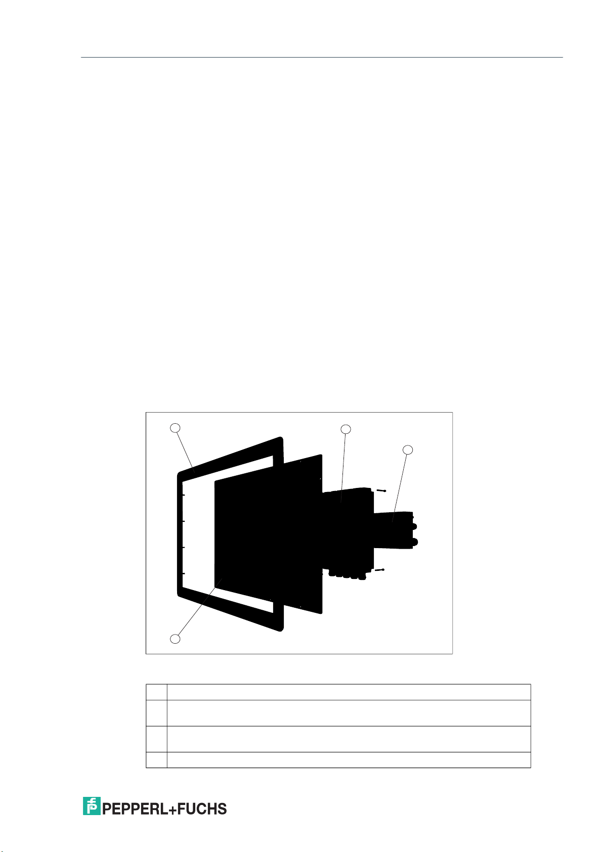
Mechanical specifications
Degree of protection IP66 (individual components and entire system with housing)
Material Internal:
Panel: anodized aluminum (TCU, PCU, PSU), powder coated
aluminum (DPU)
External:
Bezel: stainless steel AISI 304 (1.4301) System housing: stainless
steel AISI 304
(1.4301), beat blasted, typical surface roughness Ra = 0.8 µm
Installation Flush-mount installation (requires customized mounting kit)
Panel-mount installation into system housing with bezel
Panel-mount installation into cabinet with Bezel and standard
mounting kit
Mass Zone 1/21:
Panel (DPU with bezel, TCU, PSU DC): appx. 23 kg
Panel (DPU with bezel, TCU, PSU AC): appx. 24 kg
Zone 2/22:
Panel (DPU with bezel, TCU, PSU DC): appx. 17.5 kg
Panel (DPU with bezel, TCU, PSU AC): appx. 18 kg
Dimensions Panel with DC: 625 mm x 459 mm x 120 mm
Panel with AC: 625 mm x459 mm x137 mm
Panel with system housing: 625 mm x 459 mm x 173 mm
Panel cut-out: 583 mm x 417 mm (installation surface)
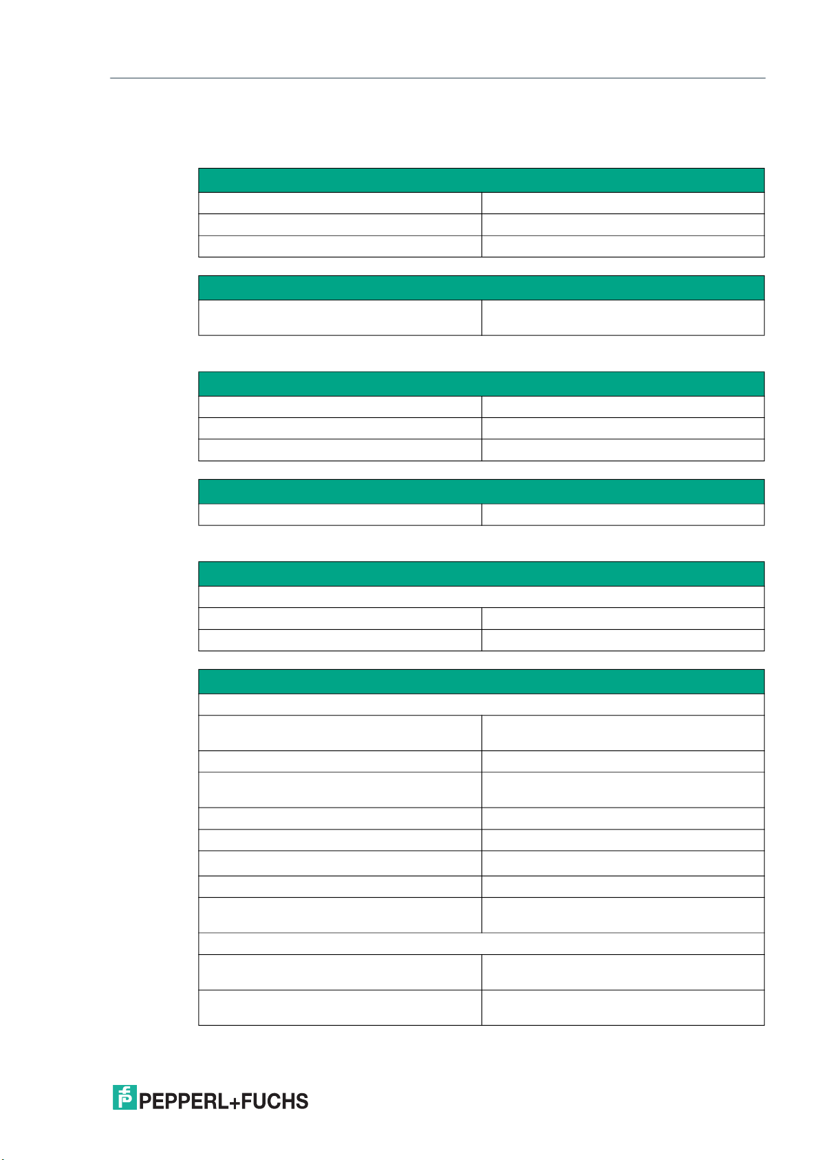
Data for application in connection with hazardous areas
EU-type examination certificate BVS 17 ATEX E 036 X
Directive conformity
Directive 2014/34/EU EN 60079-0:2012+A11:2013, EN 60079-
5:2015, EN 60079-7:2015, EN 60079-
11:2012, EN 60079-31:2014
International approvals
UL approval E492874
IECEx approval IECEx BVS 17.0029X
Standards IEC 60079-0:2011, IEC 60079-5:2015, IEC
60079-7:2015, IEC 60079-11:2011, IEC
60079-31:2013
VisuNet GXP
Technical Specifications
Zone 1/21
Data for application in connection with hazardous areas
EU-type examination certificate BVS 17 ATEX E 037 X
Directive conformity
Directive 2014/34/EU EN 60079-0:2012+A11:2013, EN 60079-
5:2015, EN 60079-7:2015, EN 60079-
11:2012, EN 60079-31:2014
Zone 2/22