Pulscon LTC
Table of Contents
DOCT-0094A 06/2009 120782
3
Brief overview . . . . . . . . . . . . . . . . . . . . . . . . 2
1 Notes on use . . . . . . . . . . . . . . . . . . . . . 5
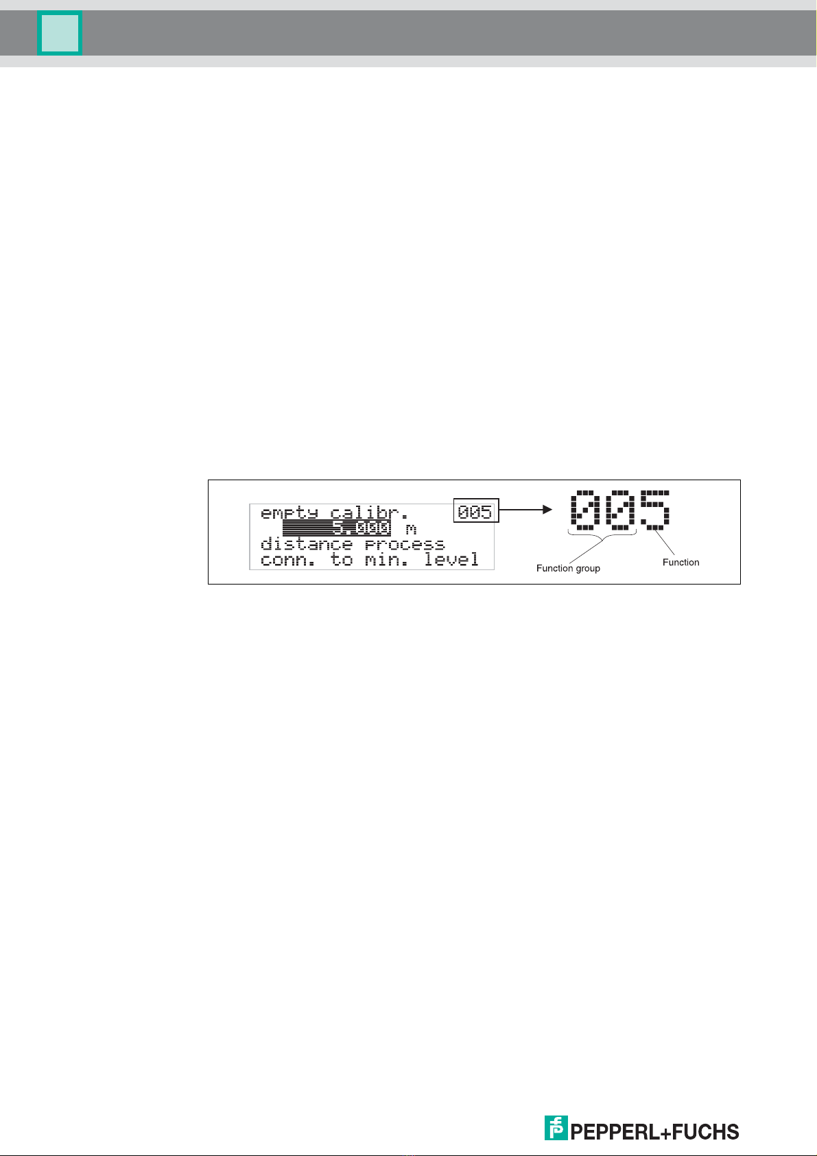
1.1 Using the table of contents to locate
a function description . . . . . . . . . . . . . . . . . . . . . . . 5
1.2 Using the graphic of the function menuto
locate a function description . . . . . . . . . . . . . . . . . . 5
1.3 Using the index of the function menuto
locate a function description . . . . . . . . . . . . . . . . . . 5
1.4 General structure of the operating menu. . . . . . . . . 6
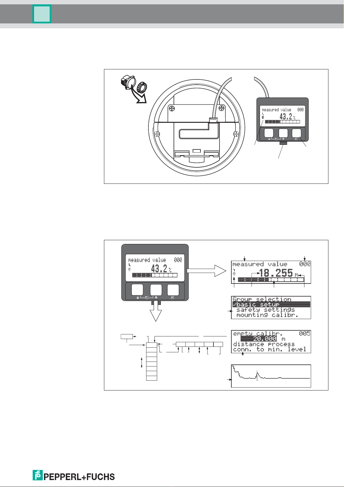
1.5 Display and operating elements . . . . . . . . . . . . . . . 7
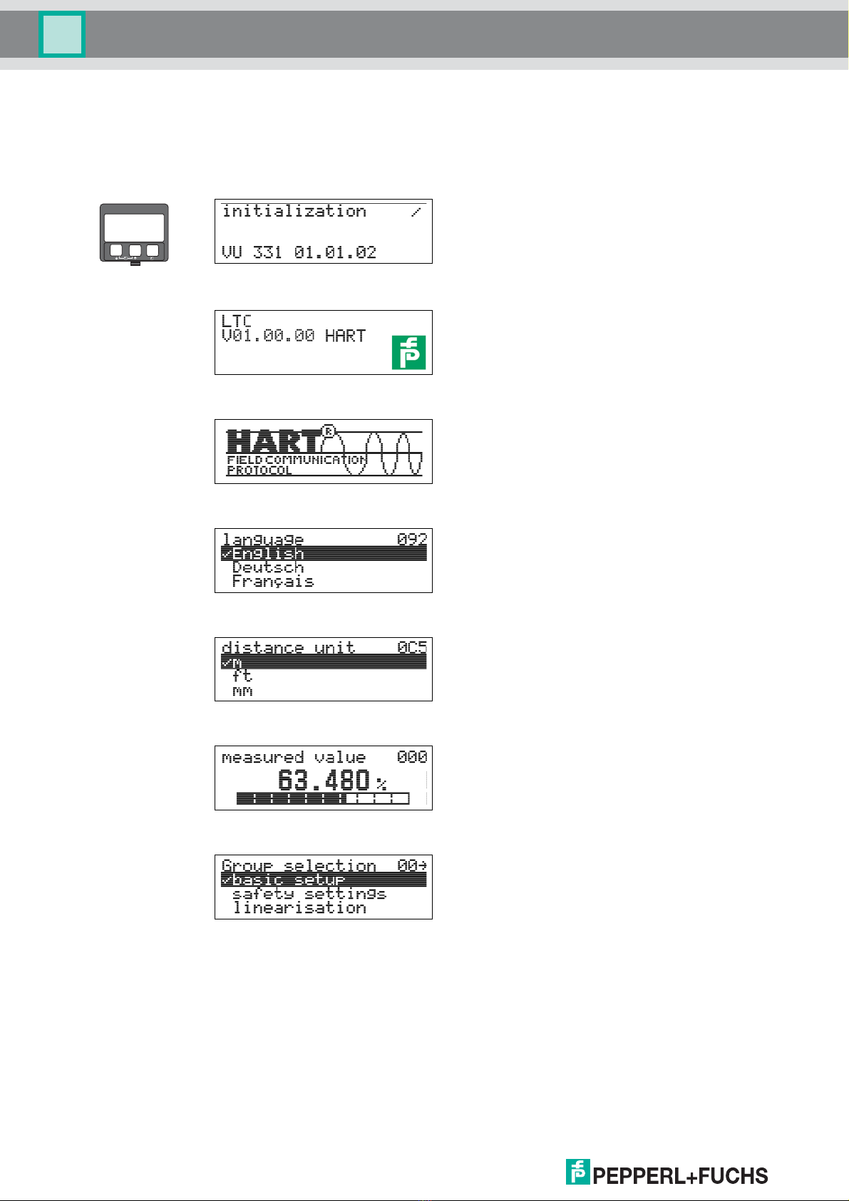
1.6 Commissioning . . . . . . . . . . . . . . . . . . . . . . . . . . . 10
2 Function Pulscon LTC . . . . . . . . . . . . 11
3 Function group "basic setup" (00). . . 13
3.1 Function "measured value" (000) . . . . . . . . . . . . . 13
3.2 Function "tank properties" (002) . . . . . . . . . . . . . . 13
3.3 Function "medium property" (003). . . . . . . . . . . . . 14
3.4 Function "process propert." (004) . . . . . . . . . . . . . 15
3.5 Function "end of probe" (030) . . . . . . . . . . . . . . . . 15
3.6 Function "probe length" (031) . . . . . . . . . . . . . . . . 16
3.7 Function "probe" (032). . . . . . . . . . . . . . . . . . . . . . 16
3.8 Function "probe length" (033) . . . . . . . . . . . . . . . . 16
3.9 Function "determine length" (034) . . . . . . . . . . . . . 17
3.10 Function "empty calibr." (005) . . . . . . . . . . . . . . . . 17
3.11 Function "full calibr." (006). . . . . . . . . . . . . . . . . . . 18
3.12 Display (008) . . . . . . . . . . . . . . . . . . . . . . . . . . . . . 18
3.13 Function "check distance" (051) . . . . . . . . . . . . . . 19
3.14 Function "range of mapping" (052) . . . . . . . . . . . . 20
3.15 Function "start mapping." (053). . . . . . . . . . . . . . . 20
3.16 Display (008) . . . . . . . . . . . . . . . . . . . . . . . . . . . . . 21
4 Function "safety settings" (01) . . . . . 22
4.1 Function "output on alarm" (010). . . . . . . . . . . . . . 22
4.2 Function "output on alarm" (011), HART only . . . . 24
4.3 Function "outp. echo loss" (012) . . . . . . . . . . . . . . 24
4.4 Function "ramp %span/min" (013). . . . . . . . . . . . . 25
4.5 Function "delay time" (014) . . . . . . . . . . . . . . . . . . 26
4.6 Function "safety distance" (015) . . . . . . . . . . . . . . 26
4.7 Function "in safety dist." (016). . . . . . . . . . . . . . . . 26
4.8 Function "ackn. alarm" (017) . . . . . . . . . . . . . . . . . 28
4.9 Function "overspill prot." (018) . . . . . . . . . . . . . . . 28
4.10 Function "broken probe det" (019). . . . . . . . . . . . . 28
5 Function group
"length adjustment" (03). . . . . . . . . . . 29
5.1 Function "end of probe" (030) . . . . . . . . . . . . . . . . 29
5.2 Function "probe length" (031) . . . . . . . . . . . . . . . . 29
5.3 Function "probe" (032). . . . . . . . . . . . . . . . . . . . . . 29
5.4 Function "probe length" (033) . . . . . . . . . . . . . . . . 30
5.5 Function "determine length" (034) . . . . . . . . . . . . . 30
6 Function group "linearisation" (04) . . 31
6.1 Function "level/ullage" (040). . . . . . . . . . . . . . . . . . 31
6.2 Function "linearisation" (041) . . . . . . . . . . . . . . . . . 32
6.3 Function "customer unit" (042) . . . . . . . . . . . . . . . . 36
6.4 Function "table no." (043) . . . . . . . . . . . . . . . . . . . . 37
6.5 Function "input level" (044). . . . . . . . . . . . . . . . . . . 37
6.6 Function "input volume" (045) . . . . . . . . . . . . . . . . 38
6.7 Function "max. scale" (046) . . . . . . . . . . . . . . . . . . 38
6.8 Function "diameter vessel" (047) . . . . . . . . . . . . . . 38
7 Function group "extended calibr." (05) 39
7.1 Function "selection" (050). . . . . . . . . . . . . . . . . . . . 39
7.2 Function "check distance" (051) . . . . . . . . . . . . . . . 39
7.3 Function "range of mapping" (052). . . . . . . . . . . . . 40
7.4 Function "start mapping" (053). . . . . . . . . . . . . . . . 41
7.5 Function "pres. map dist." (054) . . . . . . . . . . . . . . . 41
7.6 Function "delete mapping" (055) . . . . . . . . . . . . . . 41
7.7 Function "echo quality" (056) . . . . . . . . . . . . . . . . . 42
7.8 Function "offset" (057) . . . . . . . . . . . . . . . . . . . . . . 42
7.9 Function "output damping" (058) . . . . . . . . . . . . . . 42
7.10 Function "upper block. dist" (059). . . . . . . . . . . . . . 43
8 Function group "output" (06),
- "profibus param." (06),
PROFIBUS PA only . . . . . . . . . . . . . . . 45
8.1 Function "commun. address" (060), HART only. . . 45
8.2 Function "instrument addr." (060),
PROFIBUS PA only . . . . . . . . . . . . . . . . . . . . . . . . 45
8.3 Function "no. of preambels" (061), HART only. . . . 45
8.4 Function "ident number" (061),
PROFIBUS PA only . . . . . . . . . . . . . . . . . . . . . . . . 46
8.5 Function "low output limit" (062), HART only . . . . . 46
8.6 Function "set unit to bus" (062),
PROFIBUS PA only . . . . . . . . . . . . . . . . . . . . . . . . 46
8.7 Function "curr. output mode" (063), HART only . . . 47
8.8 Function "out value" (063), PROFIBUS PA only . . 47
8.9 Function "fixed cur. value" (064), HART only . . . . . 48
8.10 Function "out status" (064), PROFIBUS PA only . . 48
8.11 Function "simulation" (065). . . . . . . . . . . . . . . . . . . 49
8.12 Function "simulation value" (066) . . . . . . . . . . . . . . 50
8.13 Function "output current" (067), HART only . . . . . . 50
8.14 Function "2nd cyclic value" (067),
PROFIBUS PA only . . . . . . . . . . . . . . . . . . . . . . . . 50
8.15 Function "4mA value" (068), HART only . . . . . . . . 50
8.16 Function "select v0h0" (068),
PROFIBUS PA only . . . . . . . . . . . . . . . . . . . . . . . . 51
8.17 Function "20mA value" (069), HART only . . . . . . . 51
8.18 Function "display value" (069),
PROFIBUS PA only . . . . . . . . . . . . . . . . . . . . . . . . 51
9 Function group
"envelope curve" (0E) . . . . . . . . . . . . . 52
9.1 Function "plot settings" (0E1) . . . . . . . . . . . . . . . . . 52
9.2 Function "recording curve" (0E2) . . . . . . . . . . . . . . 52
9.3 Function "envelope curve display" (0E3) . . . . . . . . 53