Infineon XENSIV BGT60LTR11AIP User manual

Application Note Please read the Important Notice and Warnings at the end of this document V1.0
www.infineon.com page 1 of 32 2022-12-15
AN650
XENSIV™BGT60LTR11AIP Radar Shield2Go
Super low-power 60 GHz Doppler radar sensor with antennas-in-
package
Board version 1.2
About this document
Scope and purpose
This application note describes the BGT60LTR11AIP Radar Shield2Go and gives an overview of its functions. The
Shield2Go is an ultra-small Infineon Technologies PCB standard, which comes with different ICs on it intended
for different use cases.
Intended audience
This document is intended for engineers, prototype creators, hobbyists and makers –basically, anyone who
wants to work hands-on with radar, but without the need to deal too much with the development process,
focusing more on the application outcome.

Application Note page 2 of 32 V1.0
2022-12-15
XENSIV™BGT60LTR11AIP Radar Shield2Go
Super low-power 60 GHz Doppler radar sensor with antennas-in-package
Introduction
Table of contents
About this document....................................................................................................................... 1
Table of contents............................................................................................................................ 2
1Introduction .......................................................................................................................... 3
1.1 Overview..................................................................................................................................................3
1.1.1 Hardware and third-party software ..................................................................................................3
1.1.2 Quad-state input pins ........................................................................................................................3
1.1.3 SPI communication............................................................................................................................4
1.2 Key features.............................................................................................................................................4
1.3 Potential applications.............................................................................................................................4
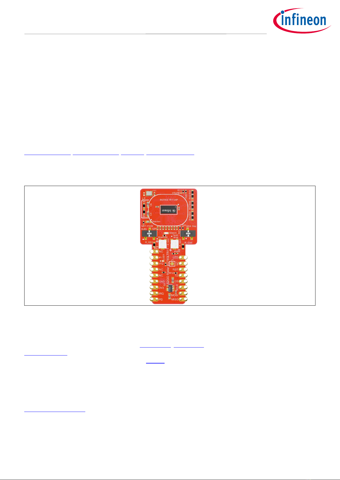
2Board and pin-out overview .................................................................................................... 5
2.1 Board dimensions ...................................................................................................................................6
3Getting started ...................................................................................................................... 7
3.1 Overview..................................................................................................................................................7
3.2 Hardware setup.......................................................................................................................................7
3.3 Software setup ......................................................................................................................................10
3.3.1 Required software for Infineon’s XMC™ boards..............................................................................10
3.3.2 Required software for Arduino ........................................................................................................10
3.3.3 Installation instructions for XMC™microcontrollers ......................................................................10
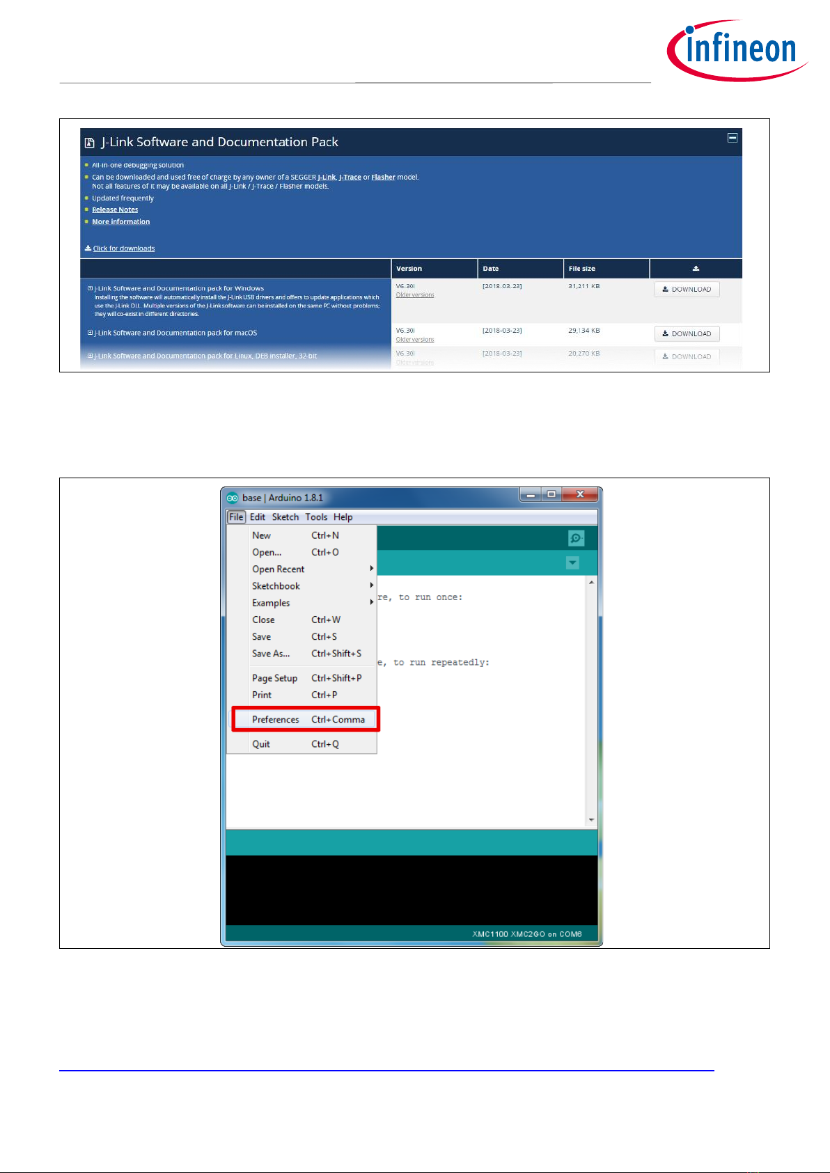
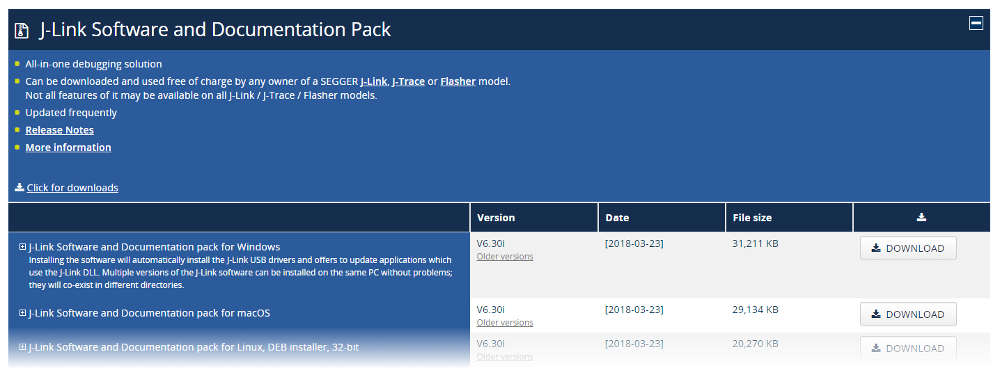
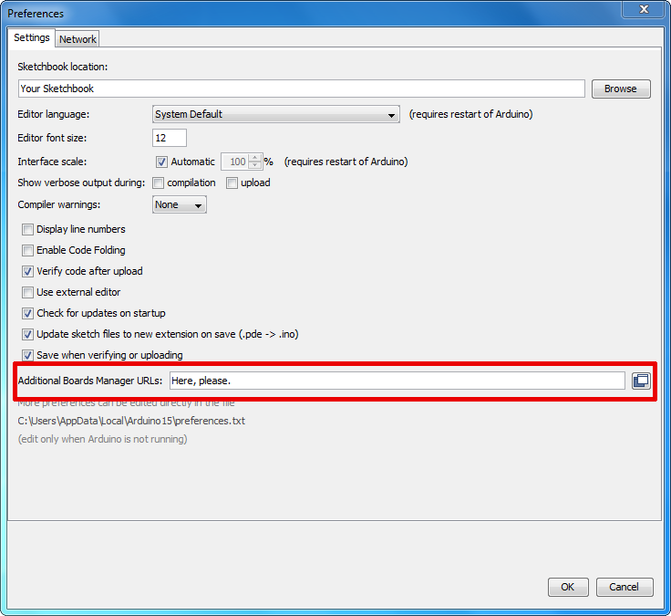
3.3.3.1 Prework for SEGGER J-Link ........................................................................................................10
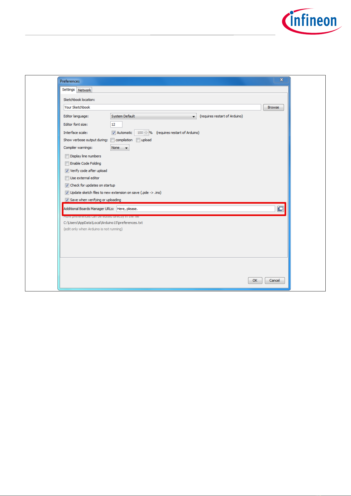
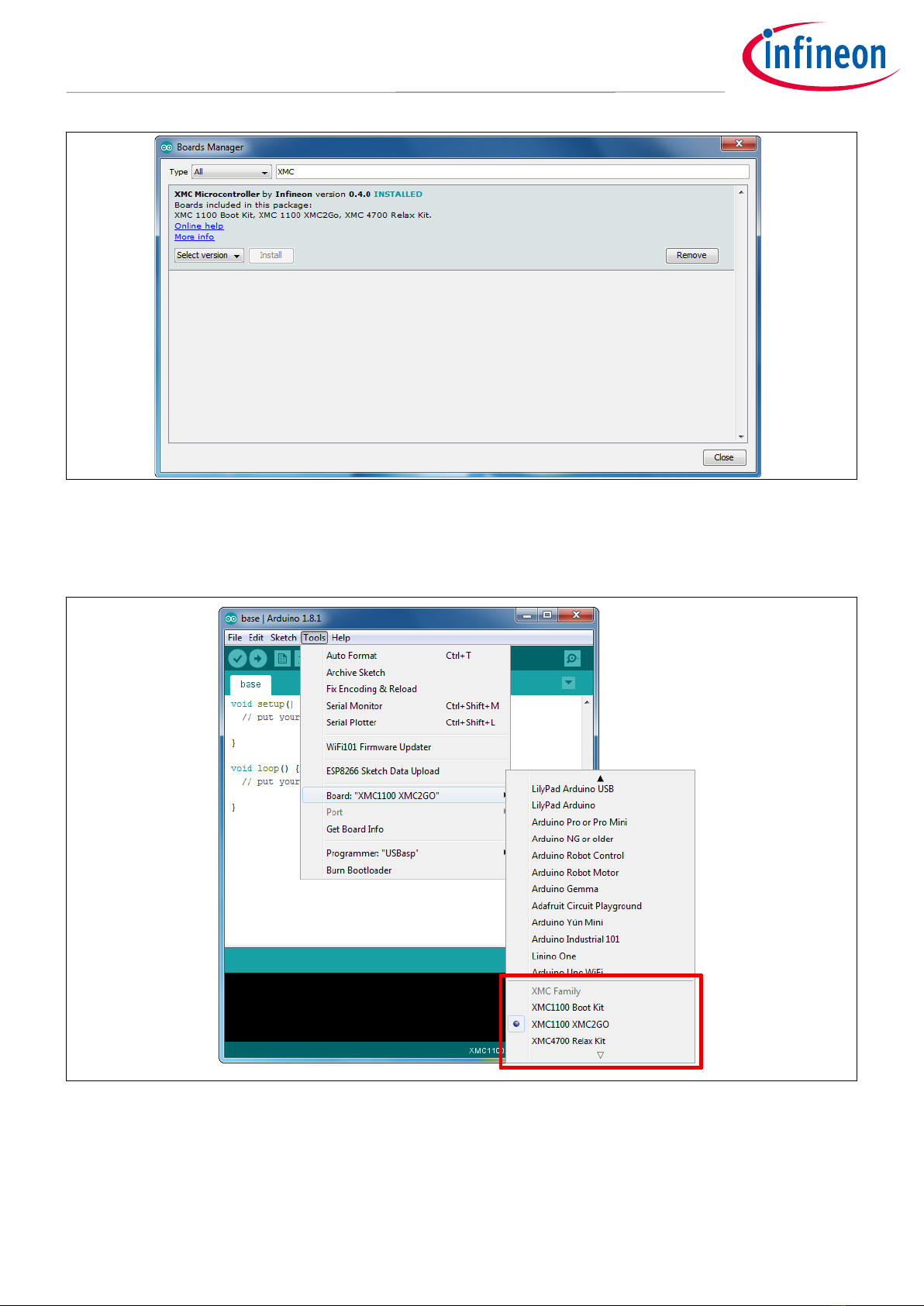
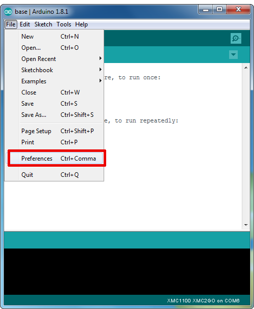
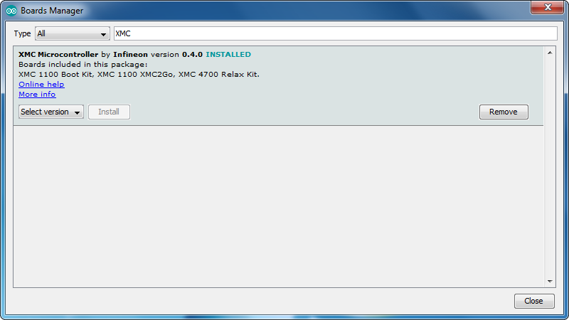
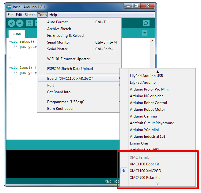
3.3.3.2 Using Arduino IDE with XMC™microcontroller..........................................................................11
4Radar modes setup................................................................................................................15
4.1 TD and PD signals..................................................................................................................................15
4.2 “Advance mode” and quad-state inputs..............................................................................................15
4.2.1 “Advance mode” ..............................................................................................................................15
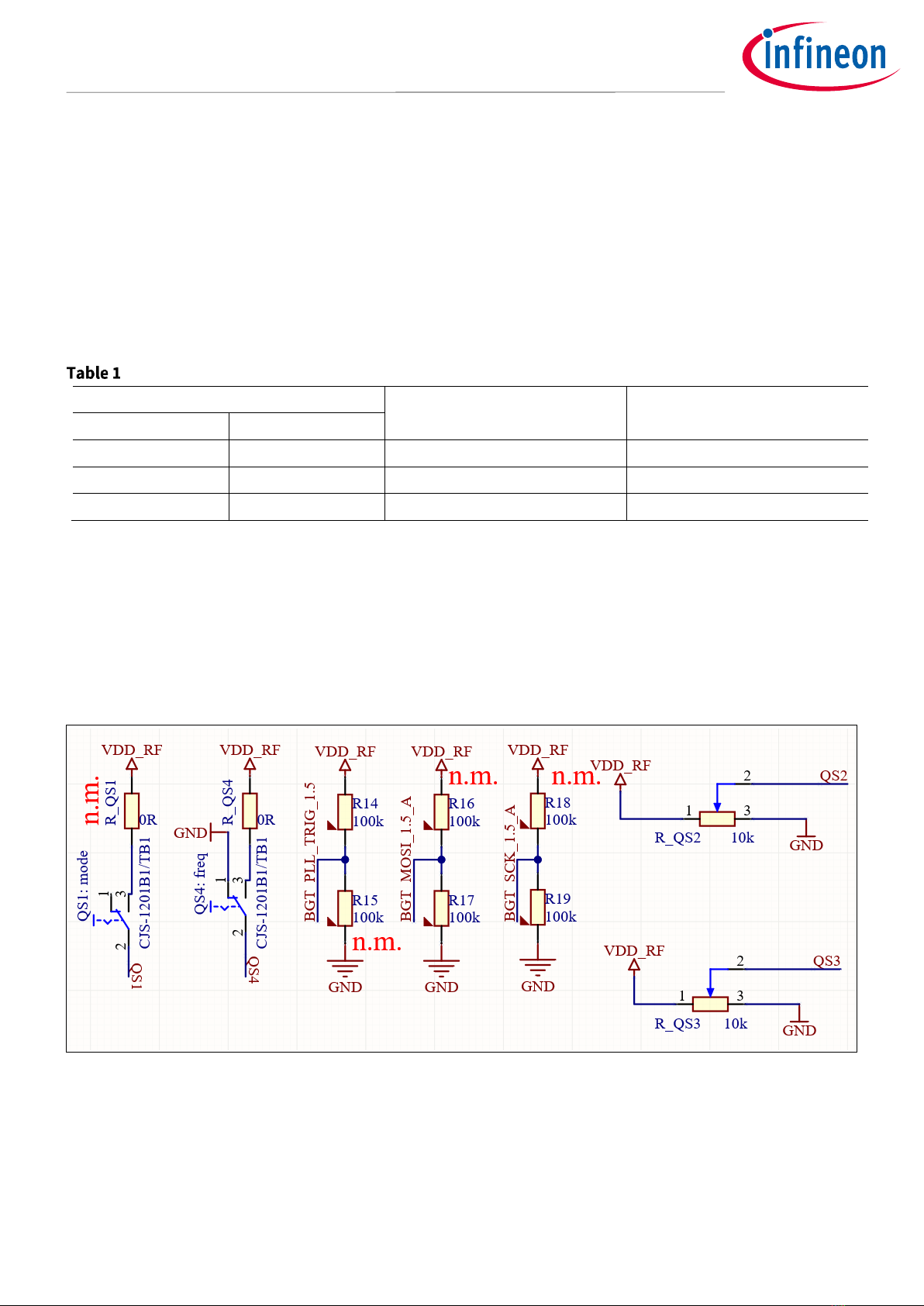
4.2.2 Quad-state basics for adjustable QS1 to QS4 signals.....................................................................16
4.2.3 QS1 –MMIC operation modes..........................................................................................................17
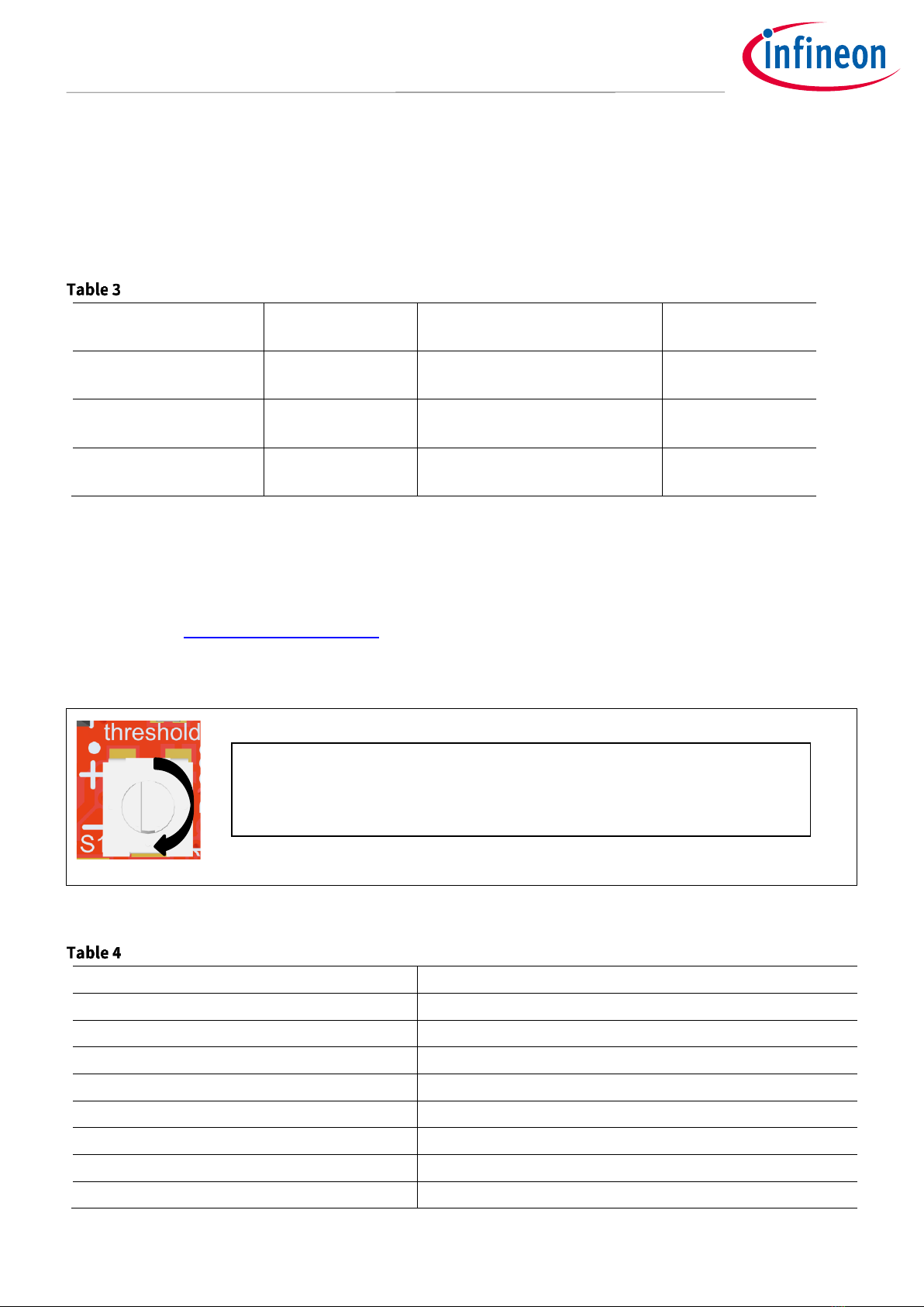
4.2.4 QS2 –detector threshold.................................................................................................................17
4.2.5 QS3 –detector hold time .................................................................................................................18
4.2.6 QS4 –operating frequency ..............................................................................................................20
5Hardware circuits..................................................................................................................21
5.1 Power supply.........................................................................................................................................21
5.2 Level shifters..........................................................................................................................................21
5.3 LEDs .......................................................................................................................................................22
5.1 Crystal oscillator....................................................................................................................................23
5.2 External capacitors................................................................................................................................24
6PCB design ...........................................................................................................................26
6.1 Layer stack-up and routing...................................................................................................................26
6.2 Bill of materials......................................................................................................................................26
6.3Schematics ............................................................................................................................................27
7References ...........................................................................................................................30
Revision history.............................................................................................................................31

Application Note page 3 of 32 V1.0
2022-12-15
XENSIV™BGT60LTR11AIP Radar Shield2Go
Super low-power 60 GHz Doppler radar sensor with antennas-in-package
Introduction
1Introduction
1.1 Overview
The Radar Shield2Go can be used independently as a “plug-in”radar sensor (e.g., with Arduino form factor
boards or another microcontroller) to detect motion and direction of motion by using only two GPIOs (TD and
PD) in autonomous mode (default). The board comes with two potentiometers and switches, making it easy to
adjust the four QS signals of the radar mechanically. The switches can be used to switch between autonomous
and SPI modes.
The Shield2Go comes with castellated holes to ensure several connection styles.
The Shield2Go family is recommended to be used with either Infineon’s XMC™maker board series (e.g.,
XMC1100 Boot Kit/XMC1400 Arduino/XMC 2Go/XMC4700 Relax Kit) or Arduino boards (e.g., Rev3/MKR1000).
The BGT60LTR11AIP Shield2Go demonstrates the features of the BGT60LTR11AIP MMIC and gives the user a
“plug and play” radar solution.
Figure 1 Radar Shield2Go with BGT60LTR11AIP
1.1.1 Hardware and third-party software
The Radar Shield2Go is compatible with the Arduino IDE, Platform.IO with Arduino extension, and Infineon’s
ModusToolbox™(formerly Cypress) SDK. You can find a detailed user guide to integrate the BGT60LTR11AIP
library on the free and open-source repository GitHub.
Note: To use the existing library in Infineon’s ModusToolbox™ SDK, the integration is done manually with
customized manifests, described on Infineon’s GitHub.
The Shield2Go concept can also be attached to any board with an Arduino Uno form factor, by using an
Infineon MyIoT adapter.
1.1.2 Quad-state input pins
The MMIC has four quad-state input pins (QS1 to QS4) that give the performance parameters flexibility when it
is running in autonomous mode. These pins are used to configure the chip, as explained in section 4.2.2.

Application Note page 4 of 32 V1.0
2022-12-15
XENSIV™BGT60LTR11AIP Radar Shield2Go
Super low-power 60 GHz Doppler radar sensor with antennas-in-package
Introduction
QS1 sets up the three modes of the MMIC (autonomous by default), QS2 controls the detector comparator
threshold, QS3 sets up the hold time of the “target detect” output, and QS4 is used to select the device
operating frequency by configuring the phase-locked loop (PLL).
QS1 is controlled by a dual-state switch and QS4 by a tri-state switch. QS2 and QS3 can be adjusted by two
rotatable potentiometers.
In autonomous mode, the detection threshold (set via potentiometer R_QS2) has 16 different levels to fulfill a
configurable detection range from 0.5 m up to 7 m with a typical human-target radar cross-section (RCS). The
hold time is also configurable as 16 levels in autonomous mode via the potentiometer that controls QS3, which
allows detection status to be held for up to 30 minutes (see section 4.2.5).
1.1.3 SPI communication
The MMIC also supports SPI mode by changing the operation mode with the QS1 pin (see section 4.2.3). In this
mode, the raw radar data can be extracted from BGT60LTR11AIP for signal processing on a PC or an external
MCU using SPI. This sampled radar data can be used to develop customized algorithms. The SPI mode offers
the possibility to control the MMIC radar completely via SPI.
1.2 Key features
•Easy motion and direction of motion detection of an object with only two GPIOs
•Programmable in Arduino IDE and Platform.IO (VS Code extension)
•Configurable detection range from 0.5 m to 7 m
•LEDs that blink when presence or movement direction is detected
•Potentiometers and switches to adjust the settings of the radar (QS)
•Super-small (48.8 mm x 23.9 mm) board design with Infineon’s Shield2Go format
•60 GHz transceiver BGT60LTR11AIP MMIC with one transmitter and one receiver unit
1.3 Potential applications
•Prototyping smart home appliances
•Security applications

Application Note page 5 of 32 V1.0
2022-12-15
XENSIV™BGT60LTR11AIP Radar Shield2Go
Super low-power 60 GHz Doppler radar sensor with antennas-in-package
Board and pin-out overview
2Board and pin-out overview
This section gives an overview of Infineon’s standardized Shield2Go pin-out.
Figure 2 The BGT60LTR11AIP Radar Shield2Go (top view)

Application Note page 6 of 32 V1.0
2022-12-15
XENSIV™BGT60LTR11AIP Radar Shield2Go
Super low-power 60 GHz Doppler radar sensor with antennas-in-package
Board and pin-out overview
2.1 Board dimensions
Figure 3 Layer stack-up of the BGT60LTR11AIP Radar Shield2Go

Application Note page 7 of 32 V1.0
2022-12-15
XENSIV™BGT60LTR11AIP Radar Shield2Go
Super low-power 60 GHz Doppler radar sensor with antennas-in-package
Getting started
3Getting started
3.1 Overview
The Radar Shield2Go needs an MCU to communicate and run custom code. However, if connected to a power
source, the direction and motion LEDs blink in the presence of an object even without an MCU connected. The
target detect (TD) pin is an active low pin. Hence, when no target is detected, the voltage level appears to be
3.3 V on this pin. The phase detect (PD) pin voltage varies, depending on the direction of the moving object.
While the target is approaching, the pin puts out 3.3 V, and when the target is departing from the radar, it puts
out close to 0 V. These pins can be read from analog pins or digital pins TD and PD.
Move the switch lever “QS1: mode” to the left position to set up the radar in autonomous mode, and apply 3.3 V
(pin 7) and GND (pin 6) to the corresponding power pins of the Shield2Go. Note that the power source offers a
minimum of 150 mA. If power is supplied, the PWR LED turns on. Now, the radar can recognize any movement
or direction of an approaching or departing object. The blue LED lights up when object movement is detected,
and the red LED lights up when the target is approaching or departing. See section 5.3 for more information
about LED behavior.
The radar now works on its own, without any other MCU needed. However, for reading/writing the radar MMIC,
connect one of the recommended MCUs mentioned in section 1.1.1. Note that any MCU will work if the voltage
levels are the same (3.3 V), otherwise level shifting is mandatory. Because Infineon offers software libraries
compatible with Arduino and Infineon XMC™boards, software setup for other MCU platforms might be more
difficult.
Infineon’s software libraries and installation guides are open-source and available on Infineon’s GitHub
channel. The Radar Shield2Go needs to be connected with the pin headers of the MCU board either with wires
or via stacking onto an adapter (e.g., Infineon’s MyIoT adapter for Arduino).
3.2 Hardware setup
Connect the Radar Shield2Go to any microcontroller and supply the board with a 3.3 V DC (150 mA) power source
(which can usually be driven by the MCU board).
Figure 4 Radar Shield2Go on top of Infineon’s MyIoT adapter and Arduino-compatible XMC1100 Boot
Kit (very bottom)

Application Note page 8 of 32 V1.0
2022-12-15
XENSIV™BGT60LTR11AIP Radar Shield2Go
Super low-power 60 GHz Doppler radar sensor with antennas-in-package
Getting started
Figure 5 Shield2Go connector S1 schematics
After that, connect the microcontroller board via USB to your computer and continue with the software setup as
described in section 4.
Note: By using Infineon’s MyIoT adapter, you can easily plug up to three Shield2Gos on an Arduino Uno
Rev3 form factor due to the integrated level shifter on the adapter. The adapter works with 5 V
(e.g., Arduino Uno Rev3) and 3.3 V shields (e.g., XMC1100 Boot Kit/XMC4700 Relax Kit). Please read
the MyIoT adapter manual for more details on how to configure the voltage shifting.
The following boards are recommended for use and are compatible with the Arduino IDE and Platform.IO.
Figure 6 Recommended boards

Application Note page 9 of 32 V1.0
2022-12-15
XENSIV™BGT60LTR11AIP Radar Shield2Go
Super low-power 60 GHz Doppler radar sensor with antennas-in-package
Getting started
•XMC2Go is equipped with Infineon’s powerful Arm® Cortex®-M0 based microcontroller XMC1100 and is
the ideal board in Shield2Go form factor for tiny applications.
•XMC1100 Boot Kit or XMC1400 Arduino are powerful microcontroller boards with Arduino Uno Rev3
form factor that offer the user more performance and GPIOs, including multiple buses (I2C, SPI), pulse-
width modulation (PWM) signals, ADC, DAC, LEDs, and a breakable and reusable debugger for multiple
purposes.
•XMC4700 Relax Kit is an extremely powerful microcontroller board with Infineon’s Arm® Cortex®-M4
based microcontroller XMC4700. It also comes in an Arduino Uno Rev3 form factor, with an additional
80 GPIOs to use, and Ethernet.
You can also use Arduino’s boards, such as the popular Arduino Uno Rev3 or the MKR1000
Wi-Fi board. We have prepared examples of applications on the do-it-yourself website
Hackster.IO for you –check out the Infineon_Team Channel for more information.
Find all libraries and instructions to get started on Infineon’s GitHub repository.

Application Note page 10 of 32 V1.0
2022-12-15
XENSIV™BGT60LTR11AIP Radar Shield2Go
Super low-power 60 GHz Doppler radar sensor with antennas-in-package
Getting started
3.3 Software setup
3.3.1 Required software for Infineon’s XMC™ boards
•Segger J-Link, either for Windows or Linux (for XMC™)
•Arduino IDE, either for Windows or Linux
•XMC-for-Arduino (installed with Arduino IDE)
•Radar BGT60LTR11 Library for Arduino on Infineon’s GitHub repository (installed with Arduino IDE,
v2.0.0 or higher)
1) Install Arduino IDE. If you are new to Arduino, please download the program and install it first.
2) Install XMC™board. The official Arduino boards are already available in the Arduino software,
but other third-party boards such as the Infineon XMC™MCU-based board need to be explicitly
included. Follow the instructions in the link to add the XMC™board family to Arduino.
3) Install the library. In the Arduino IDE, go to the menu Sketch > Include library > Library
Manager. Type BGT60LTR11 and install the library.
4) Additionally, install Segger J-Link if you are using an Infineon XMC1100 Boot Kit or XMC4700
Relax Kit. Continue with the section below if you are using Infineon’s XMC™ microcontroller for
Arduino.
3.3.2 Required software for Arduino
•Arduino IDE, either for Windows or Linux
•Radar BGT60LTR11 Library for Arduino on Infineon’s GitHub repository (installed with Arduino IDE,
v2.0.0 or higher)
1) Install Arduino IDE. If you are new to Arduino, please download the program and install it first.
2) Install the library. In the Arduino IDE, go to the menu Sketch > Include library > Library
Manager. Type BGT60LTR11 and install the library.
3) Additionally, install Segger J-Link if you are using an Infineon XMC1100 Boot Kit or XMC4700
Relax Kit. Continue with the section below if you are using Infineon’s XMC™ microcontroller for
Arduino.
3.3.3 Installation instructions for XMC™ microcontrollers
You can also find the whole XMC-for-Arduino installation guide for Infineon’s XMC™ repository on GitHub.
3.3.3.1 Prework for SEGGER J-Link
In order to use and program the Infineon XMC™microcontrollers in the Arduino IDE, SEGGER J-Link must be
installed on your PC. Please follow this link to SEGGER J-Link and install the J-Link software and
documentation pack for your operating system. If you have already installed DAVE™–Development Platform
for XMC™Microcontrollers you can skip this step, as the respective drivers/programs are already installed on
your system.

Application Note page 11 of 32 V1.0
2022-12-15
XENSIV™BGT60LTR11AIP Radar Shield2Go
Super low-power 60 GHz Doppler radar sensor with antennas-in-package
Getting started
Figure 7 Arduino configuration –installing J-Link software for XMC™microcontrollers (not needed for
Arduino)
3.3.3.2 Using Arduino IDE with XMC™ microcontroller
Figure 8 Arduino IDE configuration –Preferences
Paste the following URL into the “Additional Boards Manager URLs”input field under File > Preferences to add
Infineon’s microcontroller boards to the Arduino IDE. (It is easier to copy –there is no clickable link.)
https://github.com/Infineon/XMC-for-Arduino/releases/latest/download/package_infineon_index.json

Application Note page 12 of 32 V1.0
2022-12-15
XENSIV™BGT60LTR11AIP Radar Shield2Go
Super low-power 60 GHz Doppler radar sensor with antennas-in-package
Getting started
Note: The former “package_infineon_index.json”URL will no longer be maintained after version 1.4.0.
Upcoming versions will not be shown as available in the board manager.
Figure 9 Arduino IDE configuration –Additional Boards Manager URLs
To install the boards, please navigate to Tools > Board > Boards Manager... and search for “XMC”. You will find
options to install the board files for the microcontrollers. Click “Install”to add the boards to your Arduino IDE.

Application Note page 13 of 32 V1.0
2022-12-15
XENSIV™BGT60LTR11AIP Radar Shield2Go
Super low-power 60 GHz Doppler radar sensor with antennas-in-package
Getting started
Figure 10 Arduino configuration –installing XMC™library
In the boards listed under Tools > Board, the XMC™microcontroller boards are added and can be used from
now on.
Figure 11 Arduino configuration –choose your XMC™board

Application Note page 14 of 32 V1.0
2022-12-15
XENSIV™BGT60LTR11AIP Radar Shield2Go
Super low-power 60 GHz Doppler radar sensor with antennas-in-package
Getting started
Important notes
•This integration will only work for Arduino IDE 1.5 or above.
•The XMC1100 Boot Kit has limitations compared to the official Arduino boards (consult the XMC-for-
Arduino Wiki for more information).
•Refer also to the LICENSE.md/txt file for further information.
•Arduino 1.8.0 IDE might have problems with the XMC-for-Arduino releases.
•XMC-for-Arduino support for “arm-linux-gnueabihf”is only up to version 1.1.

Application Note page 15 of 32 V1.0
2022-12-15
XENSIV™BGT60LTR11AIP Radar Shield2Go
Super low-power 60 GHz Doppler radar sensor with antennas-in-package
Radar modes setup
4Radar modes setup
4.1 TD and PD signals
With the Shield2Go you can adjust all four quad-state signals (QS1 to QS4) mechanically rather than via
software. Use the potentiometers and switches to adjust all quad states in autonomous mode. In SPI mode,
you can adjust all QS signals by changing the BGT60LTR11AIP registers.
The default direction information is set to “approaching”. The truth table for the output pad voltage is shown in
Table 1.
Truth table for the output pad voltage
Output pad voltage
Motion
Approaching/Departing
TD
PD
high
high
No
N.A.
low
low
Yes
Departing
low
high
Yes
Approaching
The BGT60LTR11AIP provides four quad-state inputs, QS1 to QS4. With one quad-state input, it is possible to
get four states from one input pin. These pins are used to configure the chip.
4.2 “Advance mode” and quad-state inputs
On reset of the digital main controller and during the initialization sequence some chip input pins are sampled
to determine the configuration the chip should start with. Figure 12 shows the schematics of the default
configuration for the MMIC operation modes and settings.
Figure 12 MMIC operation modes and settings (n.m. = not mounted)
4.2.1 “Advance mode”
When the PLL_Trig pin is “0”as the digital main controller wakes up from reset, the chip boots in basic mode
(not advanced mode). When the pin is kept at “1”during chip boot and QS1 is either GND or OPEN, pins SPIDI

Application Note page 16 of 32 V1.0
2022-12-15
XENSIV™BGT60LTR11AIP Radar Shield2Go
Super low-power 60 GHz Doppler radar sensor with antennas-in-package
Radar modes setup
and SPICLK are also sampled to determine the PRT: dc_rep_rate (Reg7[11:10]). In addition, pins QS2 and QS3
are evaluated by the ADC and converted into 4-bit values before each “mean window”.
By default, the Radar Shield2Go is pulled to VDD_RF (1.5 V) with a 100 kΩresistor R14; hence, “autonomous
mode” is activated. Additionally, “advance mode”is activated.
When this pin is 0, when the digital main controller wakes up from reset, the chip boots like earlier versions,
only considering the four quad-state inputs below with their 2-bit information per pin.
PRT in “advance mode”
PLL_Trig
SPI_MOSI
SPI_CLK
dc_rep_rate
0
*
*
1/2 (fuse dependent)
1
0
0
1
1
0
1
3
1
1
0
0
1
1
1
2
4.2.2 Quad-state basics for adjustable QS1 to QS4 signals
Figure 13 Overview of QS1 to QS4 signals on the BGT60LTR11AIP Radar Shield2Go from the top
The quad-state inputs QS1 to QS4 enable configuration of four different states with one input pin. Figure 13
shows the two switches QS1/QS4 and two potentiometers for the detector threshold (QS2) and hold time (QS3).
Table 3 shows possible input states and the resulting internal signals in the binary description. Quad-state
inputs are sampled at the start of the init sequence by the internal main controller at power-up. A change after
this sampling has no effect. Resampling can be triggered by setting the reset pin or activating the soft reset by
writing the corresponding bit in register 15 (Reg15). The reset pin is by default pulled to VDD (3.3 V) via the 10 kΩ
resistor R12.
In order to have up to 16 settings for QS2 (threshold) and QS3 (hold time), the PLL_TRIG should be connected to
VDD by removing R15 and placing R14 = 100 kΩ. This will put the MMIC into “advance mode”. Note that advance
mode is set by default.
Switch QS1:
mode
Switch QS4:
mode
Potentiometer R_QS2:
threshold
Potentiometer R_QS3:
Hold time

Application Note page 17 of 32 V1.0
2022-12-15
XENSIV™BGT60LTR11AIP Radar Shield2Go
Super low-power 60 GHz Doppler radar sensor with antennas-in-package
Radar modes setup
4.2.3 QS1 – MMIC operation modes
QS1 is used to select the mode of the chip. By default, it is recommended to use either (advance) autonomous
mode or SPI mode. Advance mode allows the use of 15 instead of four threshold values for QS2 (threshold) and
QS3 (hold time). By default, this board comes with advanced autonomous and SPI mode settings. Change
resistor R_QS1 to enable/disable the other modes, by soldering it accordingly, as described in Table 3.
QS1 settings
Switch position –
QS1 mode
QS1
Operation mode of the MMIC
PCB configuration
Left position (floating)
Open (default)
Autonomous pulsed mode
Not important
(default)
Right position
100 kΩ to VDD
SPI mode with external 9.6 MHz
clock enabled (FH3840024Z)
R_QS1* = 100 kΩ
Right position
VDD
SPI mode
R_QS1* = 0 Ω
(default)
* R_QS1 is assembled with 0 Ω, 0603 (imp.)
4.2.4 QS2 – detector threshold
QS2 is used to select the detector threshold value; with the same radar cross-section as a target, a lower
detector threshold value corresponds to a higher detection range, which is written into register 2 (Reg2) as
described in the BGT60LTR11AIP User Guide.
Additionally, QS2 can be controlled by the 10 kΩpotentiometer R_QS2 to adjust the thresholds. To increase the
voltage, turn the knob clockwise; to reduce the voltage, turn the knob counterclockwise.
Figure 14 Rotation direction of R_QS2 potentiometer –detector threshold
QS2 settings –detector threshold
Pad
Detector threshold
0*VDD/16 –1*VDD/16
61 (left endpoint of potentiometer)
1*VDD/16 –2*VDD/16
66
2*VDD/16 –3*VDD/16
80
3*VDD/16 –4*VDD/16
90
4*VDD/16 –5*VDD/16
112
5*VDD/16 –6*VDD/16
136
6*VDD/16 –7*VDD/16
192
7*VDD/16 –8*VDD/16
248
Rotate potentiometer R_QS2 clockwise to increase the voltage and hence the
detection threshold. Rotate it counterclockwise to reduce the detection
threshold.

Application Note page 18 of 32 V1.0
2022-12-15
XENSIV™BGT60LTR11AIP Radar Shield2Go
Super low-power 60 GHz Doppler radar sensor with antennas-in-package
Radar modes setup
Pad
Detector threshold
8*VDD/16 –9*VDD/16
320
9*VDD/16 –10*VDD/16
384
10*VDD/16 –11*VDD/16
480
11*VDD/16 –12*VDD/16
640
12*VDD/16 –13*VDD/16
896
13*VDD/16 –14*VDD/16
1344
14*VDD/16 –15*VDD/16
1920
15*VDD/16 –16*VDD/16
2560 (right endpoint of potentiometer)
Due to mechanical tolerances and manufacturing differences in the potentiometer, it is difficult to predict the
degree of rotation of the potentiometer. Table 5 gives an orientation for the configuration of the threshold,
hence the radar’s range. Please note that your values may differ slightly from the values below.
Measured threshold vs. range of Radar Shield2Go in advanced autonomous mode (for
reference only)
Measured potentiometer
voltage “VDD_RF-QS2”(V1)
Measured
potentiometer voltage
“GND-QS2”(V2)
Expected detector
range
Comment
1.412 V
0.173 V
7.66 m
Leftmost position
1.378 V
0.207 V
6.9 m
1.296 V
0.289 V
5.8 m
1.144 V
0.441 V
5.4 m
0.929 V
0.656 V
4.76 m
0.794 V
0.791 V
4.1 m
0.665 V
0.92 V
2.48 m
0.577 V
1.008 V
2.1 m
0.388 V
1.197 V
1.7 m
0.229 V
1.357 V
1.2 m
0.108 V
1.477 V
0.93 m
0 V
1.585 V
0.45 m
Rightmost position
4.2.5 QS3 – detector hold time
Figure 15 Rotation direction of R_QS3 potentiometer –detector hold time
Rotate the knob of potentiometer R_QS3 clockwise to increase the voltage
and hence the detection hold time. Rotate it counterclockwise to reduce the
detection hold time.
Note: V1 is the potential between the potentiometer’s terminals
(GND and QS2).
V1

Application Note page 19 of 32 V1.0
2022-12-15
XENSIV™BGT60LTR11AIP Radar Shield2Go
Super low-power 60 GHz Doppler radar sensor with antennas-in-package
Radar modes setup
QS3 is used to select the hold time of the Tdet_o output, and it is written into Reg10 as described in the
BGT60LTR11AIP User Guide.
QS3 settings –detector hold time
Pad
Detector hold time
0*VDD/16 –1*VDD/16
100 ms (left endpoint of potentiometer)
1*VDD/16 –2*VDD/16
500 ms
2*VDD/16 –3*VDD/16
1 s
3*VDD/16 –4*VDD/16
2 s
4*VDD/16 –5*VDD/16
3 s
5*VDD/16 –6*VDD/16
5 s
6*VDD/16 –7*VDD/16
10 s
7*VDD/16 –8*VDD/16
30 s
8*VDD/16 –9*VDD/16
45 s
9*VDD/16 –10*VDD/16
1 min.
10*VDD/16 –11*VDD/16
90 s
11*VDD/16 –12*VDD/16
2 min.
12*VDD/16 –13*VDD/16
5 min.
13*VDD/16 –14*VDD/16
10 min.
14*VDD/16 –15*VDD/16
15 min.
15*VDD/16 –16*VDD/16
30 min. (right endpoint of potentiometer)
Due to mechanical tolerances and manufacturing differences in the potentiometer, it is difficult to predict the
degree of rotation of the potentiometer. Table 7 gives an orientation for the configuration of the QS3 voltage,
hence the radar’s hold-time. Please note that your values may differ slightly from the values below.
Measured voltage vs. hold-time of QS3 potentiometer in autonomous mode (for reference
only)
Measured
potentiometer voltage
QS3
Expected detector hold-
time
Measured detector hold-
time
Comment
0 V
100 ms
Less than 1 s
Leftmost position
0.112 V
500 ms
Less than 1 s
0.279 V
1 s
1.37 s
0.355 V
2 s
2.21s
0.493 V
5 s
5.54 s
0.713 V
30 s
30 s
0.898 V
60s
60s
1.06 V
90 s
90 s
1.134 V
2 min.
2 min.
1.248 V
5 min.
5 min.
1.452 V
15 min.
15 min.
Rightmost position

Application Note page 20 of 32 V1.0
2022-12-15
XENSIV™BGT60LTR11AIP Radar Shield2Go
Super low-power 60 GHz Doppler radar sensor with antennas-in-package
Radar modes setup
4.2.6 QS4 – operating frequency
QS4 is used to select the device operating frequency by configuring the PLL. Frequency is also dependent on
the Japan e-fuse. The QS4 signal can be adjusted by using the tri-state switch “QS4: freq” on the Shield2Go.
QS3 settings –operating frequency
Switch position –
QS3 mode
QS3
Operating frequency
PCB configuration
Left position
Ground
61.1 GHz
Not important
Middle position
(floating)
Open (default)
61.2 GHz
Not important
Right position
100 kΩ to VDD
61.3 GHz
R_QS4 = 100 kΩ
Right position
VDD
61.4 GHz
R_QS4 = 0 Ω (default)
*DNP = R_QS4 is assembled by default with a 0 Ωresistor. Exchange for a 100 kΩ [0603 size imp.] resistor.
Other manuals for XENSIV BGT60LTR11AIP
2
Table of contents
Other Infineon Radar manuals
Popular Radar manuals by other brands

Endress+Hauser
Endress+Hauser FOUNDATION Fieldbus Levelflex FMP51 Brief operating instructions

Furuno
Furuno FR-2105 Operator's manual

Endress+Hauser
Endress+Hauser Micropilot FMR50 Brief operating instructions

Endress+Hauser
Endress+Hauser Micropilot FMR67B operating instructions

JRC
JRC JMA-933B installation manual

Endress+Hauser
Endress+Hauser Micropilot M FMR240 operating instructions