Per Brohall Albin 25 User manual

Per Brohall
S-68101 Kristinehamn 1 .Sweden
www.jonesboatyard.co.uk

.
-
Foreword: this handbook is for AD21 engine models (years 70/72)
Theobject ofthis handbook isto provide Albin 25 owners with a concise manual on
how the boat should be used and maintained. Instructions regarding the Albin Engine
Type AD
-
21 can be found in a separate instruction book. Instructions for running in
and manouvering are repeated here. Where data in this book differs from the engine
instruction book, the instructions in this book should be followed.
Even a boat
so
well equipped as the Albin 25 may, after delivery and launching, re
-
quire some adjustments, e.g. trimming of rig; minor engine adjustments; tightening
of
screws, nuts and hose clips; and repairs to minor damage sustained during ship
-
ment. The manufacturer will naturally stand by his guarantee, but the low price of
Albin 25 is calculated on the basis that a normally handy owner can himself take care
of
maintenance items such as mentioned above. This means that the manufacturer's
resources can be used more effectively for guarantee repairs where skilled person
-
nel are really required.
If
there are any problems which are not discussed in this handbook don't hesitate to
write to Albin Marin AB for advice.
We wish you a happy time with the Albin 25.
2
www.jonesboatyard.co.uk

Fig.
1.
The
lines.
Per
BrohaII:
The
ALBIN
25
handbook
CONTENTS
...........
..............
2
.......................................... 3
Performance and characteristics
...
...........
5
Influence
of
thepropeller onmanoeuvring
............................. 7
First launching
..........
Engine installation and maintenance
..........................
Interior and equipment
.........................................
Winter storage and spring commissioning
......................
Tie her up right
......
Sails on Albin 25.
...................................... .
29
32
More general advice
.
.
........
..................
10
10
15
Glassfibreandmaintenance
.............................
........
23
...
,,
25
.......................
26
......................................
www.jonesboatyard.co.uk

Technical data
The
motorboat
ALBIN
25
Designer Per Brohall
.........
7.6 m 25ft.
0
in.
6.75 m 22 ft. 2 in.
Beam 2.6 m
8
ft. 6 in.
0.7 m 2 ft. 4 in.
Height from mast support to deepest part of keel
....
2.75 m
9
ft.
Height from mast support to waterline
..............
2.1 m 7 ft.
Displacement (empty boa
.....
1.600 kilos, 1.6tons
Maximum speed, about
...
8
knots
Economical speed, about
.........................
7 knots
Sound level at helm
...............................
74 db
..................................
Fig.
2.
Accomodation
and
stowage plan (example).
Engine installation
Engine, Albin 4
-
stroke diesel type AD
-
21 with single lever teleflex control of engine
Maximum revs
..................................
2300
-
2400 rpm
Engine power at maximum rpm
....................
Economical rpm about
............................
Idling speed about
...............................
Maximum idling time with gears in neutral
..........
Fuel consumption
at
economical rpm
...............
revs and gearbox.
22 horsepowerSAE
17
horsepower
DIN
2000 rpm
650 rpm
30 min.
2.2 I/h
0.55
US.
gal./h
0.45 Imp. gal./h
3
www.jonesboatyard.co.uk

Oil quantity when changing tonew oil
..............
Oil quality
......................................
Oil viscosity
....................................
Oil pressure (with warm engine).
..................
Cooling water temperature
....................
Direction of engine rotation (looking forward)
........
Reduction rear ratio
...
.......................
Propeller shaft of stainless acid proof steel with two
inner sealing rings and a rubber mounted outer bear
-
ingof water lubricated fibre.
Shaft diametre
..................................
Rotating direction of the propeller seenlooking forward
Propeller
3
bladed
............................
Alternator
.......
Lighting battery capacity
..........................
Starting battery capacity
.............
3-3.5litres
0.68-0.75 Imp. gal.
0.8-0.9
US.
gal.
Service DMor DHoil for diesel engines
SAE
30
2--3 kp/cm2
28-43Ib/sq. in.
70-85°C
anti
-
clockwise
2.04:
1
25 mm
anti
-
clockwise
161/2
x
1
2“
12volts
490 watts
57-60 Ah
57-60 Ah
Fig. 3. Air ducts and sound-proofing for the engine
.
Glassfibre lamination
The thickness of the
hull
is 6 mm in the topsides and 8 mm below the waterline. The
hull is strengthened with glassfibre angles
-
stringers and frames
-
and by floors,
engine bed and air ducts laminated into the hull.
Horizontal areas of
deck and cabin top
are sandwich construction with acore material
of Divinycell (PVC cellular plastic).The top laminate is 3.5 mm (5/32”) thick, the Divi-
nycell 15mm
(5/8”)
andthe inner laminate 2.5mm
(1/8"")
Certain areas have apres
-
sure proof filler of polyester and Vermiculite (a mineral product). Moulded into the
deck areconduits forthe electrical wiring andwooden blocks totake the various
through bolts. The deck is bolted and laminated to the flange on the hull and the joint
is covered with a toe rail of PVC plastic.
Engine cover
of glassfibre is sound insulated with 30 mm sound deadening foam. The
engine bed has sealed bushings for fuel, water and exhaust lines and rubber bushings
for electrical wires and control cables. The engine room is completely sealed off from
the hull. Leaking oil cannot spread and smell throughout the bilges.
Windscreen
and
side windows
are made of hardened glass. Fore and aft cabin curved
windows are of acryllic glass.
The
rudder
is made of glassfibre. The
rudder stock
is 25 mm acid proof stainless steel
and is glanded with a water lubricated fibre bushing. The wheel
steering gear
and
flexible cable are by Teleflex. The flexible cable works
a
rudder arm on the rudder
4
www.jonesboatyard.co.uk

stock. Thewheel turns twofull revolutions from side toside giving a rudder angle of
35
"
each side. If the flexible cable isloosened from the rudder,arm aspare tiller can
be mounted directly into the rudder arm.
Fuel
tank is made of Argon welded stainless steel plate with a capacity of 75 litres
(16.5 Imp. gal., 20
Us.
gal.).
Water tank is made of Polithene with a capacity of 65 litres (14 Imp. gal.,
17
US.
gal.).
Performance and characteristics
Stability
If the power and length
of
a motorboat are increased the speed is increased, but if
the weight (displacement) is increased, there is a
loss
of speed. The Albin 25 has
been designed around its engine to produce the most efficient boat, obtaining the
best speed with available power. This means that the boat must be light. Therefore
the necessary stability is achieved by means of a suitable hull shape
-
giving form
stability. Fig. 4 shows just how the force of gravity
(P)
works from the centre of
gravity and how in a heeled position a similar force works vertically up from the
centre of displacement. If we multiply displacement
(P)
(in this case 1680 kilograms)
times the length
of
the moment arm (distance 0.25 metre between the two forces) we
get the stability moment which is the
"
power
"
which will bring the boat back to an
upright position. Heeling an Albin 25 up to 50
degrees (empty boat with mast and boom and
one person on the cabin top) the accompa-
Fig.
4.
Sectionshowing stability moment.
nying stability curve was measured a (fig. 5).
For heeling angles larger than 50 degrees the
stability moment has been calculated as
shown. As a comparison the sailboat Vega
has about twice as large a stability moment
up to heeling angles of 50 degrees. A normally
loaded Albin 25 weighs more than the test
boat and also has a lower center of gravity.
Because of this the loaded boat gains even
better stability than the curve shows.
It
shows
that the Albin 25 is as good as uncapsizable
and that you can use rig and sail without any
risk of capsizing. It also shows that ballast is
not necessary from a stability point of view.
Ballast decreases speed through increased
weight and if the ballast is put deep into the
boat
it
can also give a less comfortable move
-
ment to the boat.
Period
of
roll
The results of such good stability give the
Albin 25 a comparatively quick natural period
of roll (time of swing from one side to the
other and back).
A
longer period of roll gives
a more comfortable athwarthship movement
in a seaway. The formula for calculating the
period of roll
(t)
is:
t=
1.108xradius of inertia
metacentric height
Radius of inertia means the distance from the
axis of rotation to a theoretical point where
the mass of the boat is concentrated when
rolling around this axis. The radius of inertia
can be considered about the same as the
length of a pendulum. The meaning of the
meta
-
centric height is shown in fig. 4 which
also shows that this height is a measure of
stability. An increase
or
a
decrease of the
meta
-
centric height gives an increase or de
-
crease of stability. Seemingly
it
is possible to
lengthen the period of roll through decreasing
the meta
-
centric height (the same as raising
the center of gravity
of
the boat which is the
5
www.jonesboatyard.co.uk

same as decreased stability) or through increasing the radius of inertia (putting
weights farther from the axis of rotation). Here are examples how these factors can
be used to effectively dampen
a
boat's movements in a seaway:
1.
On sailing yachts you can hoist a heavy anchor up the rigging (decreasing meta-
centric height and increasing radius of inertia without increasing weight).
2. On an Atlantic passenger ship the motion in
a
seaway was unsuitable for pas
-
sengers. The cure was 200 tons of stone on top of the upper deck.
The same effect has been measured on the Albin 25. The period of roll was measured
with an empty boat, with one man (85 kilograms) positioned in different places. The
following times were measured:
low position
...............................
2.05seconds
at thehelmsmans place
.....................
2.15 seconds
on top ofthe cabin
.........................
2.40seconds (anincrease of 25%)
Ballast and movements in a seaway
The above technical discussion on the period of roll has been given to give
a
back
-
ground to the following advice regarding ballast or no ballast. Several owners of the
Albin 25 think that the boat will have a calmer motion if ballast is used and many more
ask questions regarding ballast. One publication has advised that a ballast of 500
kilos be used down in the bilges. With conflicting advice it seems advisable to discuss
this question more thoroughtly. The reasons usually given as to why'ballast should be
used is the desire to obtain better stability and calmer motion in a seaway. Here we
have two conditions contrary to each other and where it will be necessary to choose
a suitable compromise.
Increased stability
is notnecessary. This is clearly shown inthestability curve fig. 5.
When the weight of the boat is increased with equipment, provisions etc., the stability
is increased and much more
so
if everything is stowed deep down in the boat.
Calmer movements in a seaway:
The main part of the discomfort experienced in a
motorboat in a seaway is caused by the athwarthship movements
-
the rolling.
There is the unhappy case where the period of the wave train is the same as the
boats natural period of roll and the motion of the boat therefore is increased. An
alteration of the course may change this. Each boat and each size of boat has a type
of sea which is especially uncomfortable.
Albin 25 has been designed for comfortable motion in normal use, loaded with a full
crew and all necessary equipment. The hull form gives a very comfortable movement
in a headsea. In certain types of seaways and also in open anchorages the boat can
develop relatively quick, uncomfortable athwarthship movements because of its form
stability. In open waters with a short and uncomfortable sea, calmer athwarthship
movements can be had through using:
1.
Sails.
A mast in itself is enough to increase the roll period and give a calmer
motion. With sails and a good wind the movement is considerably dampened.
2.
Mechanical stabilization.
There are several different systems, as a rule they are
too expensive.
3.
Lengthening the period
of
roll.
Through his own efforts the owner can increase
the period of
roll
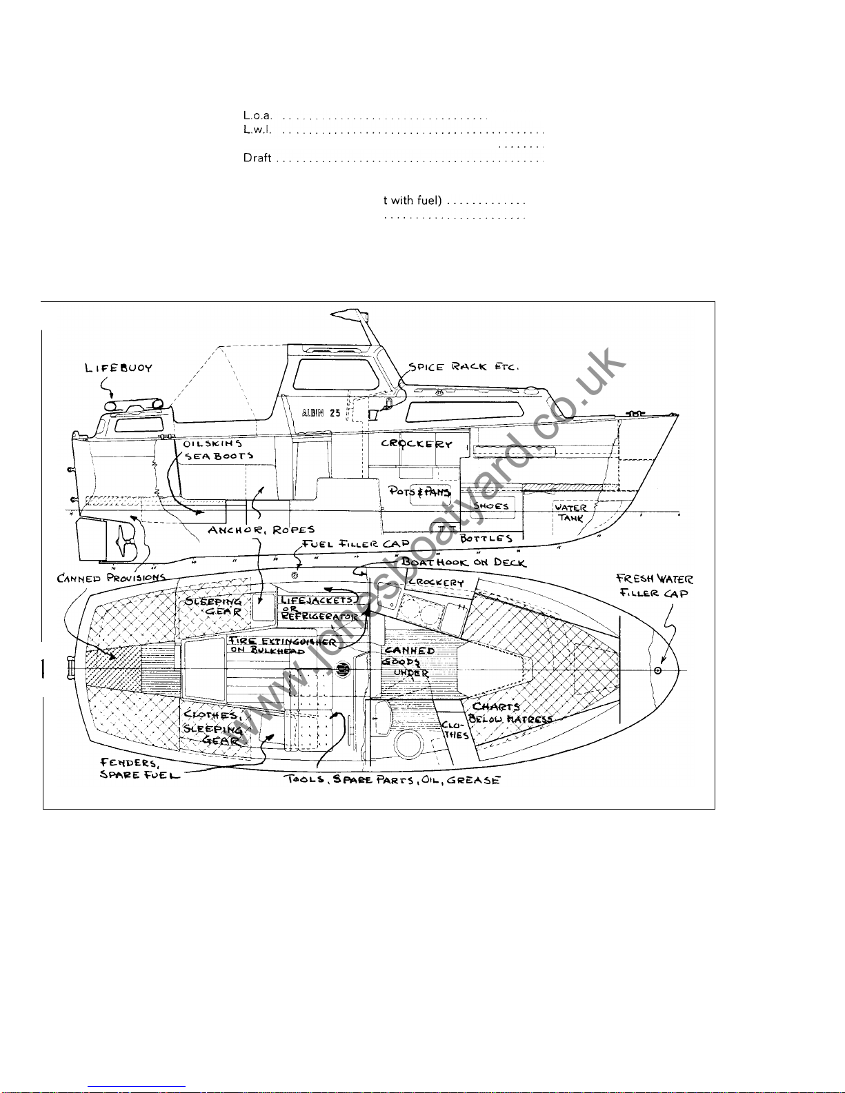
by stowing all equipment and cargo (provisions, drink, etc.) as
high up and as far out to the sides as possible. A dinghy and anchor stored on
the deck helps for instance to give a better motion. An increase in the total weight
of the boat increases the radius of inertia if the increase of weight does not ride
on the axis of rotation.
To
use ballast is not advised if it is possible through other efforts to improve the
movement of the boat to satisfy your personal taste. If ballast is used to dampen the
movements it should be stowed high up and as far out to the sides as possible. Such
ballast must be fastened thoroughly
so
as not to come adrift in a seaway. If ballast
is
placed deep down, the meta
-
centric height is increased (which shortens the period
of roll). The radius of inertia is increased considerably if ballast is placed high up and
far out to the sides. It is a completely faulty use of ballast to place it far down hoping
for better motion, and the effect may be only 25% of what the right position will give.
Don't forget that every increase in weight also decreases the speed, increasing fuel
consumption. For instance
500
kilograms of ballast results in a reduction of maximum
speed byabout 3/4 ofaknot (10%) and a reduction of cruising speed by
about 1/3 of a
knot (5%).
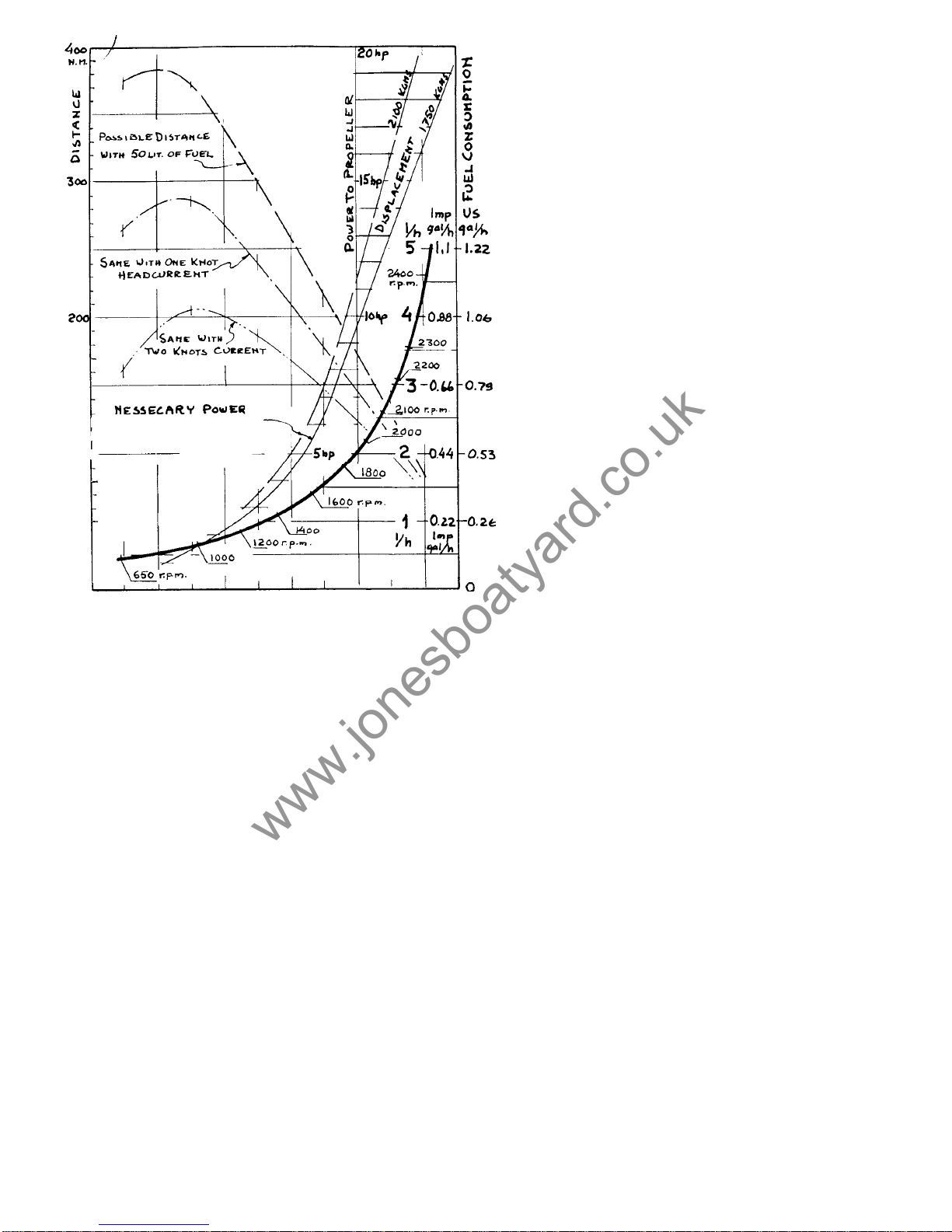
Fuel consumption and speed
Fig.
6
shows how much power must be delivered to the propeller to give the Albin 25
a certain speed. The power shown is about equal to the
DIN
power minus 5% to 10%
(losses in alternator, gearbox, shafts, bearings, etc). The efficiency of the propeller at
around
58%
is good. It follows that the thrust is a little more than half of the available
6
www.jonesboatyard.co.uk

power. Thecurves fordisplacements
of
1750
kilograms and 2100 kilograms give anidea of
what anincrease inweight means. That an in
-
crease
of
power isneeded with increased
speed isstill more clearly shown
-
a
speed
of
8
knots requires
12to15times asmuch
power asfor
4
knots!Atlowspeed the resist
-
ance ofthe boat ismainly friction (about
95%
ofthe total resistance) at
8
knots the frictional
resistance is about 55%ofthe total resist
-
ance - the rest isform resistance - wave
resistance plus afewpercent air resistance.
It is important tohave aclean bottom with the
least possible frictional resistance.
Fuel
consumption
at different revs and speeds
also appear infig.
6.
These values are the re
-
sults
of
many measurements and can becon-
bythe tachometer
of
the
boat
canatfull revs
sidered correct towithin 5%.The rpmshown
show upto 150rpmtoo little and sometimes
up to 50rpm too much. Atcruising revs the
fault isconsiderably smaller -about
60%
of
theerror atfull rpm. Atidling rpm the fault is
very small. The speeds shown are forcalm
weather without anysea. Also inthe diagram
there are 3curves showing the largest pos-
sible distance covered with 50litres offuel.
These show howeconomical itistousealow
rpm if itisdesired to goasfar aspossible
with acertain quantity offuel. Thecurves
shown forone ortwo knots head current can
also beused ifthe speed isdiminished by
headwinds and headseas. They show how the
most economical rpmincreases ashead cur
-
rent increases.
3
KNOTS
4
5
b
7
a
Do
not trust aspeed log which hasnot been
tested andcalibrated. It isnotunusual that
the log canshow more than oneknot error.
.
FOR
DIFFERENT SPEEDS
A
N
D
DISPLACEMENTS
I00
Fig.
6.
Fuel
consumption
and
resistance.
Influence
of
the
propeller on
manoeuvring
Thedirection thepropeller rotates has acertain influence on amotorboat. Figs.
7
to
13show this. Itcan be added that the rudder effect when going astern is notasgood
on boats with thepropeller sheltered behind adeep keel asonboats where the
propeller andrudder are completely unsheltered. Itwould bewise to practice all
types of manoeuvering on open water with different wind directions. From such test
manoeuvers itwill bepossible tojudge and make successful manoeuvers indifficult
situations later on. The effect of the wind on the boat is mostly felt at low speeds and
can be rather large.A good knowledge of this effect, the best speed
for
manoeuvering,
radius of turns in different situations, influence
of
the propeller, etc. is necessary if
you are to manoeuver without risk
of
damage to your own or other boats. With the
propeller thrusting
-
propeller wash against the rudder
-
the turning radius is about
a
boat lenght. There is no great difference in turning radius between low and high
speeds. From full speed ahead you can stop the Albin
25
in one boat lenght if the
gearbox is used in the right way.
7
www.jonesboatyard.co.uk

To
beable to go
astern inthein
-
tended direction it
isimportant to
have the right
initial position.
I
Fig.
8.
Initialposition when going astern.
Fig.
7.
Thepropeller
of
theAlbin
25
is
anticlockwise(look-
ing forward seengoing ahead)
The rotating propeller stream
pushes
on
thekeel and bottom.
In
the lower positionsthepro-
peller blades work
in
less disturbed water. Thisadds upto
a
side
force, which isnoticeable whenstarting
from
laying still es
-
pecially when going astern.
The turning radius
can be influenced
bywind andwaves.
When going ahead
the turning radius
it's slightly smaller
when turning
to
star
-
boardthan when
turning
to
port.
t
When going astern
from lying still the
turning radius
is
very much influ
-
enced bythe side
force o
peller.
8
www.jonesboatyard.co.uk

Full
rudder and power
during the whole turn.
Full
power
Fig.
10.
When
turning
against thew
ind
the
turning
radiuscan be smaller than when
turning with the
wind.
\\
\
\
\\\
\
\
\\
Astern
speed
Slow speed
\\\
\
\
\\
Astern
speed
Fig.
Approaching
a
quayside. Withtheport side against thequay themanoeuvre is
best done with
a
continous turn. Approaching with thestarboard side isdone on
a
stright
course. Thepropeller sideforce lays theboat smoothly alongside when going astern.
I
Toleave
a
quayside when thewind isblowing against it.
If
theport side istied
Fig.
12.
to the quay itiseasier togo astern
and
get off
.
Fig.
13.
Theengine canbe used
to
turn
theboat with thestern against thequay.
9
www.jonesboatyard.co.uk

First launching
Albin 25 is delivered in a shipping cradle which has been with the boat since she first
took shape. The boat is fastened to the cradle with two iron rods which tie down the
middle at each side. The rods have threaded ends and nuts at the deck and at the
cradle below.
A
crane and lifting straps are needed to lift the boat out of the cradle.
The recommended launching procedure
is
as follows:
1.
2.
3.
4.
5.
6.
7.
8.
9.
10.
Learn beforehand about the mooring placeyou will use after launching and check
that necessary lines, fenders and anchors are handy.
Loosen the nuts on the rods at the deck
so
that the rods can glide down and
the boat is free from the cradle.
Put the strops around the boat ahead and astern of the cradle. The strops are
then hooked into the lifting hook of the crane. When the strops are tightened
their position should be corrected
so
that they do not touch any sharp edges.
Check: that the bottom drain plug is closed,
that the seacock for the engines cooling water is open,
that the engine cooling water draincocks on the port side of the engine
Close the seacocks for the discharge
of
the toilet, washbasin and sink to avoid
possible risk
of
leakage during launching. They can be opened one at a lime for
checking when the boat has been launched.
Check for water in the bilges, looking under all floorboards. If there
is
any water
open the valve to the automatic bilge pump on the motor which will then pump
out the water when the motor has been started. This valve should be closed
when the bilge pump is not needed.
Lift the boat free from the cradle.
The unpainted portions
of
the boat which have been against the cradle are now
painted with the paint delivered with the boat.
Lift and launch the boat.
Loosen the straps on one side of the boat and let the crane lift the straps up on
the quayside. The engine was test run before delivery and there is fuel in the
tanks for several hours running. Check the level in the battery and the oil level
in the engine
-
in addition to the checks mentioned in paragraph
4
above. Top
up with fuel as soon as possible.
Follow
the instructions in next chapter when
starting the engine.
are closed.
Engine installation and maintenance
The Albin AD
-
21 engine has only one lubricating point which is situated in the aft part
on the top
of
the engine. The oil filler point and the dipstick are very easy to reach
through the circular inspection hatch on the
top
of
the engine cover, fig.
14.
Reverse gear,
reduction gear and fuel injection pump are Iu-
bricated from the common lubricating system.
When changing theoil 3-3.5litres (0.65-
0.75 Imp. gal.,
0.8-0.9
US.
gal.)
of
new oil
will be needed. Oil has to be changed every
100
hours
or
once each season if the engine
is used
a
shorter time during the season. The
first oil change should be made after
25
hours
running. Empty the used oil when the engine
is warm with the help of the oil pump which is
included with the tool kit. The lubricating oil
filter cartridge should be changed every
300
hours or once a season at the same time as
the oil change.
The engine is cooled with sea water. The cool
-
ing water pump and the automatic bilge pump
are builttogether inthe same unit. Bothpumps
are a rubber impeller type and the bearings
are water lubricated. The working temperature
of the engine is regulated by a thermostat.
The right temperature is 70-85°C.
10
www.jonesboatyard.co.uk

The reverse gear is a spring loaded type
which is self
-
adjusting. In neutral the reverse
gear is completely free when the propeller
shaft is standing still.
Procedure before the first start
Beforethe engine is started the first time after
launching the following precautions should be
taken.
1.
2.
3.
4.
5.
6.
7.
Fig.
15.
Engine installationand batteries.
8.
Fig.
IG.
Propeller shaft with oil
pocket, cooling water seacock
and
cock for
9.
bilge pump.
Remove the helmsmans seat. Remove the
floorboards and the floor over the battery
box (under the helmsmans seat). Unfasten
the clasps on the engine cover and fold it
aft (fig. 15).
Check the acid level in the batteries. The
level should be about 10 mm above the
plates. Fill with distilled water if the level
is too low.
Check that the battery cables are con
-
nected.
The motor has been filled with lubricating
oil at delivery. Recheck the oil level. It
should be between the two marks on the
dipstick not lower than the lower mark
and not higher than the upper mark.
Check that the cooling water seacock is
open (fig. 16).
Open the bottom screw on the fuel line
water separator and drain away any con
-
densed water which may have gathered
here.
When delivered, around
15
litres of fuel
mixed with inhibiting oil is put in the fuel
tank. Before starting the tank ought to be
filled with ordinary diesel oil, such as car
diesel oil.
When the engine is tested before delivery
the fuel system
is
bled free of air. Itwould
be wise to do this again before the first
start. It is important to know how to bleed
the fuel system in case you happen to get
air in the system while away cruising. This
can happen if the fuel level is too low and
the boat is rolling heavily. Try not to allow
the fuel level to fall below 10 to 15 litres.
The bleeding is preformed as follows (fig.
17):
The fuel is pumped using the manual
pumping lever. With long strokes at least
30
vertical movements will be necessary.
Then slacken the nipple bolt for the return
oil line to the fuel tank. This is fitted
on
top of the fuel filter. Continue pumping
until fuel free from air bubbles flows out.
Closethe bolt. Openthe front bleedscrew
on the fuel injection pump. Now pump
again with the pumping lever until fuel
free from air bubbles flows out. Close the
bleed screw.
Unscrew the plug on the propeller shaft
oil pocket (fig. 16
&
18) and check that it
is almost filled with grease. Fill with more
grease if necessary.
A
soft outboard grease is most suitable. The grease is
pressed directly from the tube until the oil pocket is almost full.
Do
not use high
pressure.
A
grease gun must never be used as this may press out the forward
sealing ring.
Do
not overfill the oil pocket as even screwing down the plug may
exert enough pressure to push out the sealing ring.
11
www.jonesboatyard.co.uk

10.
Re
place floorboards, engine cover and helmsmans seat. Theengine isnow ready
for starting.
1
2
Fig. 17. fuel injection pump andfuel filter.
1.
2.
Bleed screws
3.
Manual pump
4. Cold start button
Bleedscrew
for
fuel filter
I
4
I
3
Rubberbushing Oilpocket
Rubberhose
Fig.
18.
Propeller shaft sealing and bearing.
Starting
1.
2.
3.
Check that the cooling water seacock is open.
Check that the stop control is pushed in (fig. 19).
Disengage the control lever with the disengaging latch (fig. 19) and move the
control lever ahead to the starting position (position
7
in fig. 21).
Insert the starting key and turn it to position
1
in fig. 22.
Check that the yellow warning light for oil pressure and the red warning light
for
charging are on.
Push the starter switch key and turn clockwise to position
2
in fig. 22. Hold the
key there until the engine starts. The key when releasedwill return to the switched
on position (position
1
in fig. 22).
4.
5.
6.
12
www.jonesboatyard.co.uk

Stop control
R
HORN
Fig.
21.
Teleflex c
ontrols.
"
Ahead
"
-
max.
4.
"
Astern
"
-
idle
speed
"
Ahead
"
-
idle
Neutral
7.
Starting position
5.
"
Astern
"
-
max. speed
6.
Disengaging latch
I
2
0.
Neutral position
1.
Switched
-
on position
2.
Starting position
(starter motor
Fig.
22.
switched on)
Starter
switch
key.
3.
"
Radio
"
position
7.
Move the control lever back to neutral when the engine is run
-
ning evenly (position
3
in fig.
21).
Check that the yellow oil pressure warning light and red charg
-
ing warning light are out when the motor is running.
Check that cooling water is discharged through the exhaust
opening.
8.
9.
NOTE: The starter switch is also the main switch for the electrical
system of the engine. Because the engine is equipped with an
alternator the starter switch key must not be turned to off (position
0
in fig.
22)
when the motor is running as the alternator rectifier
diodes could be damaged. For the same reason the battery cables
should never be disconnected or reconnected to another battery
while the engine is running.
NOTE: If the engine is difficult to start in cold weather the cold
weather starting button on the fuel injectionpump should be pushed
in. This will supply a richer starting mixture. Set the control lever at
the starting position (position
7,
fig.
21)
then push the cold weather
starting button. It will remain in until it automatically releases when
the engine starts. The position
of
the button is shown in fig.
17.
With a little effort it is possible to reach the button through the
inspection hole in the engine cover.
If
a spray can with
"
starting gas
"
is used the cold weather starting
button need not be used. Remove the inspection hatch on the engine
cover. Use the left hand to spray down in the opening (against the
air filter) and at the same time turn the starter switch key to the
starting position. This will help to start the engine very quickly.
13
www.jonesboatyard.co.uk

Manoeuvring
The spring loaded type reverse gear requires little operating effort. This makes it
possible to use a single lever control. With this type
of
control, both the reverse
gear and engine speed are operated by means of the single control lever.
All manoeuvring should be made with distinct movements from neutral to ahead or
astern position. Positions between the marked positions 2,
3
and 4 in fig. 21 may
damage the reverse gear. When the lever goes into the proper position a definite
indentation can be felt. With the control lever in neutral (position 3, fig. 21) the
propeller is not coupled to the engine and the engine is idling at about
650
rpm.
Moving the lever forward to position 2 couples the propeller to the engine at idling
speed. Moving the lever farther forward increases the engine speed. When the lever
is moved backward to position 4 the propeller is coupled to the engine at idling speed.
The propeller is now turning in
a
reverse direction. Moving the lever farther back
increases engine speed.
The engine can be run at maximum rpm (2300 to 2400 rpm) for long periods but
2000
rprn will give much more economical cruising. Recharging of batteries during short
periods of up
to
30 minutes can be done with the engine idling and the control lever
in neutral, Charging for periods of several hours should be done with the gearbox
in forward. The engine must not be run with the propeller disengaged for any lenght
of time at higher than idling rpm.
Running
At regular intervals when running check:
that the cooling water temperature is70-85°C;
that the warning lights foroil pressure or battery charging are not lit;
that enough fuel is available;
that the lubricating oil level is right. This should be done after the engine has been
stopped for
30
minutes giving the oil time to run down to the oil sump. Over
-
filling with oil can result in oil being pressed out through the aft crankshaft seal
and being thrown around inside the flywheel casing;
that the automatic bilge pump intake is shut
off
when not needed (fig.
16).
The back
vent on the pump contains a ball vent which could, if held partly open by dirt
particles, cause flooding of the boat. Shutting off the valve also prevents intake
noise. Note: When closing this valve, be certain you are not closing the valve
for the engine cooling water;
that the acid level in the batteries is about 3/8 inch above the top of the plates. If it
is low add distilled water;
that no water has collected in the fuel line water separator. Any water should be
drained off through the bottom screw.
Fig.
23
Drain
cocks
forcooling
water.
1.
Cockfor exhaust manifold
2.
Cock for engine block
14
2
www.jonesboatyard.co.uk

Stopping
1.
Place the control lever in neutral
2. Pull out the stop control.
As
soon as the engine has stopped, push in the stop
control again. Make it a habit,then you won't run the risk of using up unnecessary
current next time you try to start with the knob out.
Turn the starter switch key back from position one to the neutral position (posi
-
tion
0)
and remove the key.
3.
Prevention of
frost
damage
In spring and autumn when there is a risk of freezing temperature the following steps
should be taken.
1.
2.
3.
After stopping the engine close the seacock on the cooling water intake, fig. 16.
Open the cooling water draincocks on the engine block and exhaust (fig.
23).
When the water has drained, start the engine and run for one minute but
no
longer
as the impeller pumps can be damaged. During this minute the engine should be
run for short bursts up to 1500 rpm. This will blow all water out of thaexhaust
system.
Rustproofing the engine for winter storage
The following steps should be taken.
1.
Add inhibiting oil such as
Esso
Rust Ban 623 to the fuel tank giving a fuel mix of
5%. If there is about 10 litres of diesel fuel left in the tank put in about
'/2
litre of
inhibiting oil.
Run the engine at least one hour. While the engine is still warm the lubricating oil
should be changed.
Clear the cooling system of water as described in the frost prevention paragraph.
The batteries should be removed and stored fully charged in a place protected
against frost.
2.
3.
4.
Procedure before the first start next season
1.
2.
3.
4.
5.
6.
Replace the batteries, fully charged and checked.
Change
oil
and fuel filters. Check that there is no water in the fuel line water
separator. When changing the fuel oil filter it is a good idea to use a plastic bag
around the filter from the underside
so
that the leaking diesel fuel is contained
inside the bag.
Top up the fuel tank.
Bleed any air from the fuel system.
Check that the cooling water seacock is open.
Put grease in the propeller shaft oil pocket.
Interior and equipment
Varnish, glue and fastening
The interior joinery is mainly
of
resin glued marine plywood with surface veneers
of
sapele on gaboon cores. The finish should normally last for several years but its life
may be prolonged by polishing with furniture polish. After a period the surface
finish will have to be renewed. The varnished parts can be treated with either alkyd
or polyurethane based varnish in accordance with the manufacturer's instructions.
15
www.jonesboatyard.co.uk

Other parts can be painted with marine paint. Teak (handrails, etc) should be oiled
several times each season. When necessary, the teak parts should be scraped and
sanded. The best and cheapest
"
teak oil
"
is
a mixture of two parts raw linseed
oil
and one part turpentine thinners.
It
can be put on with either a brush
or
a soft cloth.
Excess oil should be wiped off with a cloth moistened with thinners. If you wish to
fix hooks or other fittings to the boat they can either be screwed or glued on. Fittings
can be screwed to all wood parts. Holes should be drilled for screws. Fittings that
do not carry a great load can be screwed on to plastic surfaces with short stainless
steel self tapping screws.
It
is very important that the right size holes are drilled first.
A
dab of epoxy glue on the threads will provide considerable holding power. Epoxy
glue is
so
strong that
it
can be used to glue metal fittings on to the plastic surfaces.
This cannot be done, however, on thermo plastic.
Fittings that have to take a load must be attached with through bolts. The sandwich
deck will take the load of such bolts only where the deck is filled with wood
or
spe
-
cial filler. If bolts must be used in other places, the Divinycell filling should be re
-
moved round the hole and glassfibre and resin
or
a polyester putty put to form a
strengthening
"
tube
"
round the bolt.
A
piece of wood should be fitted under the
nuts to spread the load. Bolt holes will leak if the bolts are not packed with a rubber
gasket or sealing compound. Glassfibre does not expand when moist,
so
leaks are
not self sealing as is sometimes the case with a wood boat.
The curtains are cotton and can be washed in water. For the carpets a foam detergent
can be used. The covers for the matresses are synthetic and may be removed and
dry
-
cleaned, but it
is
a lot of work to put the covers back again. With a foam detergent
it is possible to wash the covers without removing them. Test the detergent on a spot
on the back side to ascertain that the colour does not face.
Fresh water
The water tank holds
65
litres (14% gals). The deck filler is situated right forward
on the fore deck. The level of the water in the plastic tank can be checked through
the vertical opening in the bulkhead aft of the tank.
A
thin breather pipe which finishes
just under the deck is fitted parallel to the filling pipe. If the tank is completely filled
the water level will rise up the breather pipe and a small amount of water will find
its way into the bilge; it can be removed easily with the bilge pump.
If
the tank is
completely filled a small amount
of
water may also run out into the sink and wash
basin. The tank and supply hoses can be flushed through continued filling of the
tank filling pipe. Water can then run freely through the system, into the sink and
overboard.
A
large lid is fitted to the tank to facilitate inspection and cleaning. The
forward foot pump in the galley is for fresh water and the aft one for sea water.
Skin fittings and
hose
clips
All
skin fittings below the waterline
-
inlet and outlet from the toilet, outlet from the
sink, sea water intake for the galley, and cooling water for the engine have sea
cocks to prevent the water from entering the hull if a hose or pipe should be damaged.
Skin fittings for the exhaust have no sea cocks since they can be reached from deck
and bunged up if need be.
All
hose attachements should be checked regularly for leaks and the hose clips
tightened if necessary.
Ventilation and heating
The ventilation system has been designed with scientific thoroughness by a former
chief of Swedish defence research, Hugo Larsson. This is probably the only system
that provides a well ventilated and dry boat without the use of electric fans. On hot
summer days the temperature inside the boat will be cooler than that outside.
The system is based on the principle that all fresh air is let into the accommodation
space from deep down in the cockpit. For proper efficiency the cabin doors should
be closed. This air flows down along the inside of the cold hull below the waterline.
The moisture in the air condenses on the cold surface where it runs down into the
bilges. The dehydrated air is then led to the fore and aft cabins. Fig. 24. Stale air is
evacuated through three electrolux ventilators which were first developed by Hugo
Larsson for the Vega. These ventilators withdraw air from the cabins whenever there
is any outside air motion over them regardless of direction. With a wind speed of 4
metres per second, approximately
8
knots, one ventilator can suck out
15
cubic
metres of air per hour. The air stream passing up through the ventilators can be
regulated or completely closed off by a knob (not the toilet ventilator). The starbord
16
www.jonesboatyard.co.uk

forward ventilator sucks out aidfrom the toilet compartment through a duct inside
the deck. A closed up, stationary Albin
25
can have an inside temperature 5°C
lower than outside on a hot summer day. Without this ventilation system the boat
would be like an oven. The deck has good insulation through its sandwich construc
-
tion and the inside of the hull is insulated with a lining of plastic covered textile and
foam. This insulation and the ventilation system combine to keep the boat very
moisture free during normal conditions.
If
an Eberspacher boat heater is added to the ventilation system it is possible to keep
the boat warm and dry even during very low temperature conditions. The Albin 25 is
planned for such an installation. The principle function of the heating system is shown
in fig. 24. In the completely enclosed combustion chamber of the heater, diesel oil is
burned. It
is
pumped from the main fuel tank by an electric pump. The air for com
-
bustion is taken from outside directly through the hull and the exhaust gases are let
out through the exhaust tube placed over the intake for combustion air. Fig. 25. This
makes the condition for even burning more certain. A wind blowing against the ex
-
haust opening gives the same pressure at intake and exhaust. A fan in the heater
sucks fresh air from the space with the cold wall and the air is heated when
it
passes
around the combustion chamber. The heated air is lead through a duct to a dividing
valve on the bulkhead by the control position. This valve can control the passage of
hot air to one or both cabins.
Fig.
24.
Theventilatingandheating systems.
The heater is started with a switch on the bulkhead at the far side of the toilet. Near
this switch is a thermostat where the temperature for the forecabin can be regulated.
The temperature in the aft cabin is dependent upon how the dividing valve is placed.
To hold the inside temperature 10
-
15°C higher than the outside temperature the
thermostat normally has the heater going about 25% of the time, that is 15 minutes
out of each hour. With the heater running continuously fuel consumption is about
C.3
litres an hour and with the thermostat working about 0.1 litre per hour. At the
start the heater requires 18 amperes starting current for
30
secs., after which the
17
www.jonesboatyard.co.uk

current consumption is about
3.5
amps. When the heater
is
turned off the fan con
-
tinues to run a few minutes to cool off the combustion chamber. With a fully charged
battery of
57
amp. hours, the heater can be run a couple
of
nights before the battery
needs recharging. Care must be taken that the heater exhaust fumes do not damage
fenders or cause annoyance tonearby boats. Special,instructions give further in
-
formation for the running and maintenance of the heaterand also technical data.
.
18
Fig.
21.
Fig.
26.
Toilet.
heater
25.
www.jonesboatyard.co.uk

Marine toilet
Use only toilet paper and not to much of it!
Fig.
26 shows the toilet type
"
Brydon
Boy
"
. It is flushed in the following manner:
1.
2.
Open both sea cocks (inlet and outlet)
Move the small valve lever to
"
flush
"
and pump until only water is left in bowl
and then pump still more.
Put the lever on
"
Dry Bowl
"
and pump until bowl is dry. The pumping is much
harder now. If necessary, wipe off with paper
-
switch from
"
dry
"
to
"
flush
"
.
The lever should be positioned on
"
Dry bowl
"
when the toilet is not in use
In heavy seas or when leaving the boat the sea cocks should be closed.
3.
4.
5.
Maintenance:
Do
not use strong detergents
-
they can damage hoses, rubber gas
-
kets and valves.
When laying up one of the red drain plugs in the lower part should be opened
so
that no water is left to freeze. Pump a few times.
After use in saltwater the W.C. should be flushed with freshwater to be ready for
use the next season. The W.C. should of course be cleaned.
Normal maintenance during a season may be a few drops of oil for the pump lever.
Leaks can occur at hose clips and gaskets. They may need tightening.
Electrical System
A
12 volt electrical system circuit diagram is shown in fig. 27 (1970 boats) and 28.
(Boats from the 1971 series). In the later boats the charging of the boat batteries is
regulated by a diode (when the lighting battery is fully charged the starting battery
starts charging). The first Albin 25 boats (1969) were equipped with only one battery.
The circuit diagram for these boats was delivered in a special instructions. Some
of the electrical cables run in conduits in the deck. Beside the steering wheel there
is an electrical connection which can be used for various appliances such as a hand
lamp, vacuum cleaner, razor, etc. Use the proper plug in this connection as the
wrong one can cause a short circuit. The horn, windscreen wiper, electrical outlet,
navigation lights and other lights are protected with
8
amp. fuses (Bosch
MSG 3/4
Z.,
length
25
mm). There is an extra fuse fitted for the addition of extra equipment such
as refrigerator or heater (25 Amps needed). The fuses are fitted in a box on the aft
.bulkhead of the toilet room.
There
is
a spare fuse in the box. The lighting system is
12
volts and uses the following
lamps: Navigation lights: 10 watt (Osram) 44 mm long
-
reading lights: 10 watt
(Osram) 44 mm long
-
overhead cabin lights: 15 watt (Osram 7430 bayonet base
BA 15d)
-
tachometer light:
4
watt (Osram 893)
-
other instruments: 2 watt (Osram
3898)
-
warning lamps:
2
watt (Osram 3796). 10 watt lamps use about .85 amps., 15
watt lamps about 1.25 amps.
If
a lamp or any other equipment does not work when the current
is
switched on,
check the fuse first. If the fuse is alright either the lamp is burned out or there is a
poor connection in the wiring. If the fuse is blown change to a new one. If this one
should blow also, then there is a short circuit in the wiring or the fixture. If one fuse
in particular blows often, it could mean that the curcuit is loaded with too much
additional equipment. The
8
amp. fuse can be replaced with a 15 amp. fuse. For a
heater a 25 amp. fuse is needed. Never replace a fuse with a piece of wire as this
will leave the circuit unprotected. When idling,the chargi&$power is about 200 watts.
Full charging power of 490 watts is available at 2000 rpm.The charging relay switches
off charging current when the battery is fully charged.
It
is preferable to charge
batteries slowly, with a low charging current available at 1000 rpm. Remember, the
engine must not be run at idling without the propeller turning longer than thirty
minutes. At 2000 rpm
a
battery can be fully charged in 2-4 hours.
19
www.jonesboatyard.co.uk
Table of contents