Perlesmith PSTVMC05 User manual


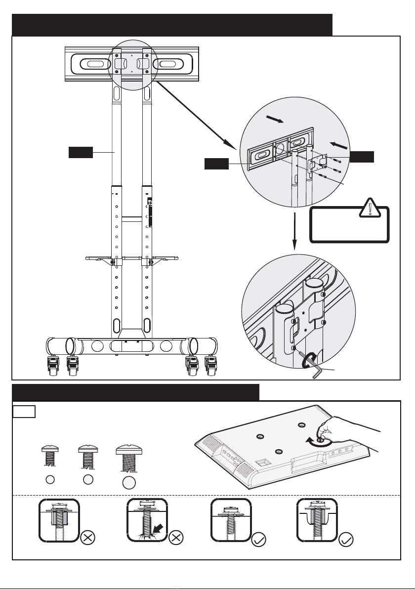
Minimum VESA pattern:200mm/8 in.(W)x200mm/8 in.(H)
Check the VESA Pattern of Monitor Before the Installation
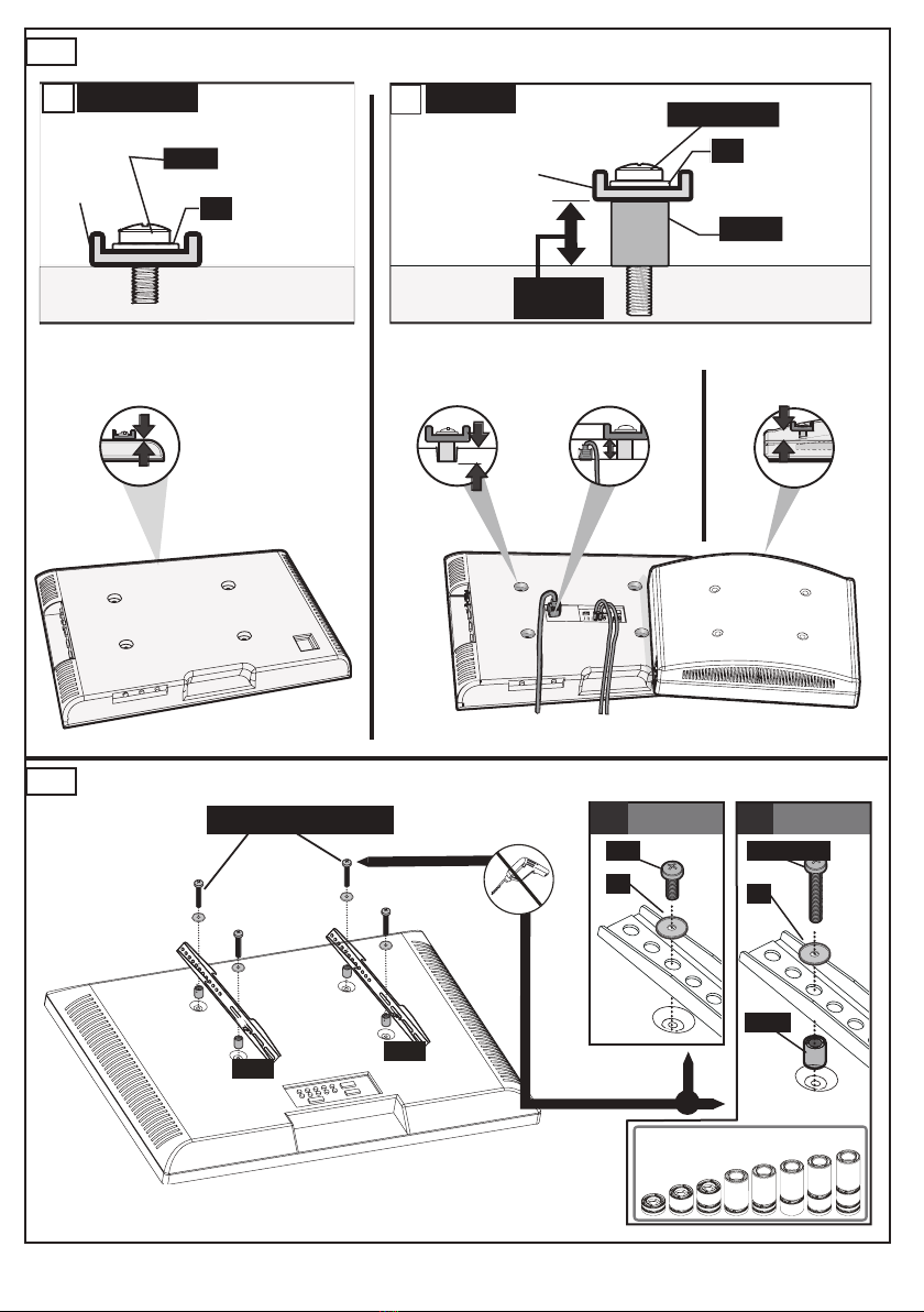
200 mm ≈ 7 7/8 in.
400 mm ≈ 15 3/4 in.
300 mm ≈ 11 3/4 in.
600 mm ≈ 23 6/10 in.
MXA:600mm/23.6 in.
MXA
:400mm/15.7 in.
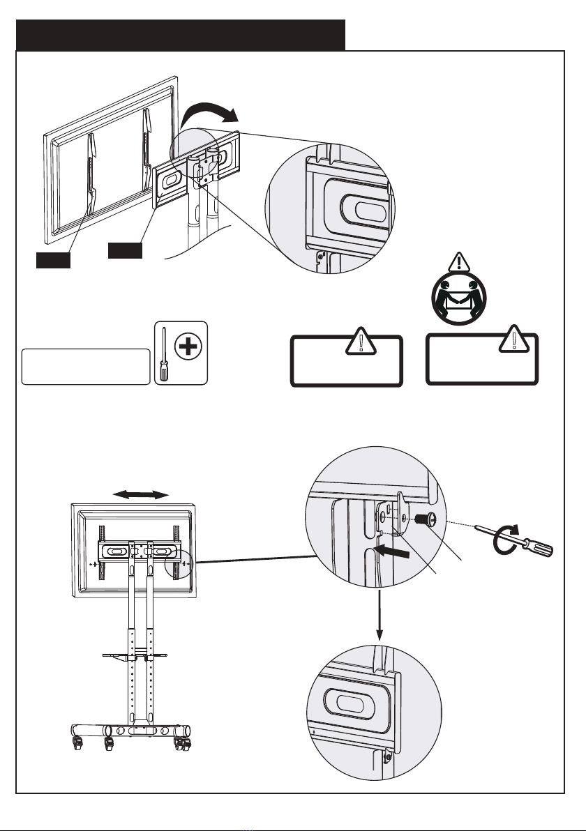
Important Safety Information
• Please read through these instructions completely before attempting installation. If you do
not understand the instructions or have any concerns or questions, please contact customer
service at [email protected].
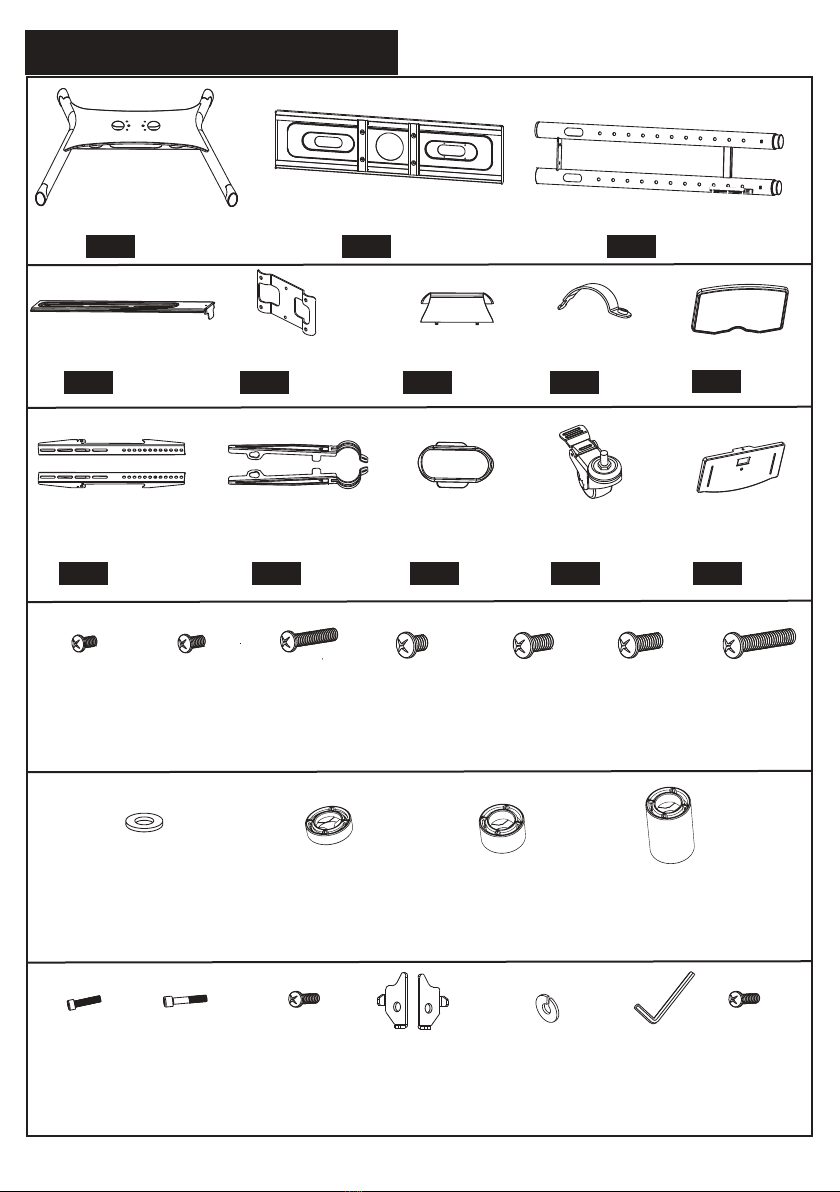
• Check package contents against Supplied Parts and Hardware List to assure that all
components were received undamaged. Do not use damaged or defective parts. lf you
require replacement parts, contact customer service at [email protected].
• Not all parts and hardware included will be used.
• Do not use this product for any purpose or in any configuration not explicitly specified in
this instruction. We hereby disclaim any liability for injury or damage arising from incorrect
assembly, incorrect mounting, or incorrect use of this product.
• Please check www.perlesmith.com for more products and company information.
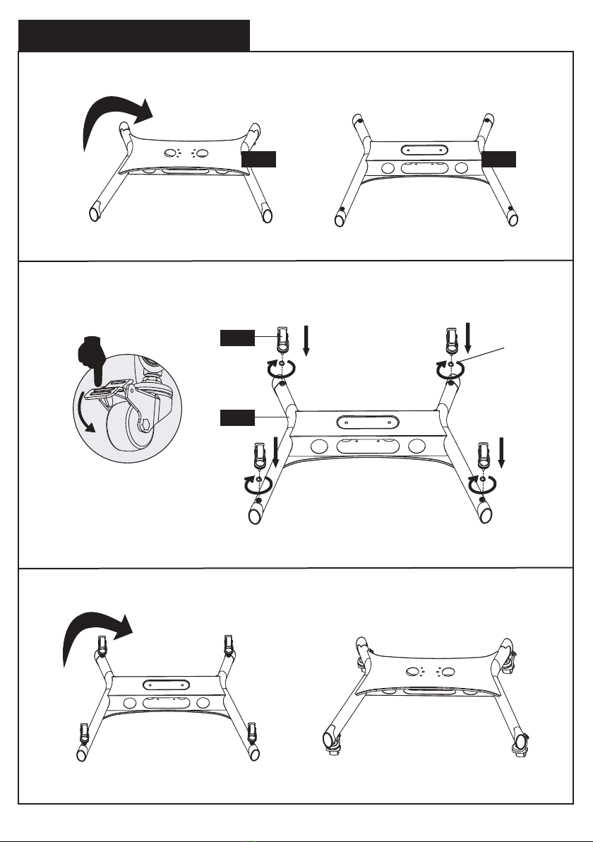
• Serious or fatal crushing injuries can occur from tipover.
PREVENT TIPOVER:
• Never allow children to climb, stand, hang, or play on any part of TV or TV cart.
• Use tipover restraint or anchor stand to wall use of tipover restraints may only reduce, but
not eliminate risk of tipover.
Tools Needed (Not lncluded)
Tape Measure Screw Driver
01 02 03 04 05 06 07 08 09 10 11 12
13 14 15 16 17 18 19 20 21 22 23 24
25 26 27 28 29 30 31 32 33 34 35 36
37 38 39 40 41 42 43 44 45 46 47 48
49 50 51 52 53 54 55 56 57 58 59 60

φ16xφ6.2x1.5
(x1)
(x2) (x2) (x4) (x4) (x1)
(x1)
04 (x1)
05 (x1)
06 (x2)
07 08
09 10 11 12 13
(x1)
01 (x1)
02 (x1)
03
Parts and Hardware Supplied
M8X26mm
A2 (x6)
M8X55mm
B2 (x4)
M5X12mm M5X10mm
C2 (x2)
D2 (x2) Ф16.5×Ф12.5×2
E2 (x4)
M6
F2 (x1) G2 (x1)
2.5mm
H (x4) I(x8)
M6x16mm
M4x30mm
B (x4)
A(x4)
M8X25mm
E (x4)
M6X35mm
C (x4)
Base Monitor Plate Height Adjustable Post
Camera Bracket Connecting Plate Decorative Cover Fixing Ring AV Shelf
Monitor Bracket Cable Cover Caster
AV Shelf
Support
R
L
Camera Tray
Bolt Bolt Bolt
M8X15mm
D (x4)
Bolt
M8X50mm
G (x4)
Bolt
M8X35mm
F (x4)
BoltBolt
Washer
Washer Wrench
Spacer
10mm
J(x4)
Spacer
23mm
K(x4)
Spacer
Bolt Bolt Bolt BoltSafety Lock
01 02 03 04 05 06 07 08 09 10 11 12
13 14 15 16 17 18 19 20 21 22 23 24
25 26 27 28 29 30 31 32 33 34 35 36
37 38 39 40 41 42 43 44 45 46 47 48
49 50 51 52 53 54 55 56 57 58 59 60

1. Secure Casters to Base
01
01
01
12
Turn the base upside down to keep the bottom side of the base upwards
Lock the casters [12], then secure the four casters [12] to the base [01]
Turn the base upside down again to keep top side of the base upwards.
E2
01 02 03 04 05 06 07 08 09 10 11 12
13 14 15 16 17 18 19 20 21 22 23 24
25 26 27 28 29 30 31 32 33 34 35 36
37 38 39 40 41 42 43 44 45 46 47 48
49 50 51 52 53 54 55 56 57 58 59 60

!
2. Connect Post Assembly to Base
Note:
Make sure cables management
windows are facing the rear of base.
Caution:
Ensure bolts are
secured firmly.
01
03
06
Fasten the four bolts [A2] using wrench [F2] to secure the height adjustable post
[03] to base [01]
Slide the decorative cover [06] to the base assembly
Front Side
Back Side
F2
A2
A2
F2
01 02 03 04 05 06 07 08 09 10 11 12
13 14 15 16 17 18 19 20 21 22 23 24
25 26 27 28 29 30 31 32 33 34 35 36
37 38 39 40 41 42 43 44 45 46 47 48
49 50 51 52 53 54 55 56 57 58 59 60

1450mm
1400mm
1500mm
1500mm
1450mm
1400mm
1500mm
1450mm
1400mm
3. Adjust the Height of the Post
Step 1.
Step 2.
Repeat step 1 for left post.
Leftupper post
Leftlower post
Spring
plunger Depress
Figure 1Figure 2
Right upper post
Use thumb or finger to depress spring plunger ball of the right upper post located
at the cable hole, then twist and pull upper post upward to your desired height.
As shown in fig-1, twist upper post toward the plunger holes direction and engage
the spring ball into the plunger hole to fix the post inplace as shown in fig-2.
01 02 03 04 05 06 07 08 09 10 11 12
13 14 15 16 17 18 19 20 21 22 23 24
25 26 27 28 29 30 31 32 33 34 35 36
37 38 39 40 41 42 43 44 45 46 47 48
49 50 51 52 53 54 55 56 57 58 59 60

Secure the AV shelf assembly
to the height adjustable post
[03] by fastening the bolts
[A2] using wrench [F2]
R
L
4. Secure AV Shelf to the Height Adjustable Post
08
10
03
10 07
Secure the AV shelf support [10] to AV shelf [08]
Fasten the AV shelf assembly to the height
adjustable post [03]
4-1
4-2
4-2-1
4-2-2
4-1-1
4-1-3
Attach the AV shelf support [10] to AV shelf [08] 4-1-2 Pull the AV shelf supports [10] down
to secure them to the AV shelf [08],
then put them to the holes on the
AV shelf [08] as shown
Secure the fixing ring [07] to the AV shelf support [10]
Attach the AV shelf
assembly to the height
adjustable post [03]
① ②
A2 F2
01 02 03 04 05 06 07 08 09 10 11 12
13 14 15 16 17 18 19 20 21 22 23 24
25 26 27 28 29 30 31 32 33 34 35 36
37 38 39 40 41 42 43 44 45 46 47 48
49 50 51 52 53 54 55 56 57 58 59 60

5. Secure the Monitor Plate to Height Adjustable Post
Secure the monitor plate [02] to height
adjustable post [03] by tightening the
bolts [B2] via connecting plate [05]
6. Secure the Monitor Bracekts to Monitor
Only one bolt size fits your TV.
M6
M4 M8
Too Short Too Long
6-1
1500m
m
1450mm
1400mm
!
Caution:
Ensure bolts are
secured firmly.
02 05
03
B2
F2
01 02 03 04 05 06 07 08 09 10 11 12
13 14 15 16 17 18 19 20 21 22 23 24
25 26 27 28 29 30 31 32 33 34 35 36
37 38 39 40 41 42 43 44 45 46 47 48
49 50 51 52 53 54 55 56 57 58 59 60

Attach the Monitor Brackets to Your Monitor
Select Spacers (if needed)
3
For Rounded TV
For Flat TV with:
Inset Holes Cable Interference
a
Short Bolt
Washer
TV Bracket
B/D
H
NO SPACER
For Flat TV
Spacer not necessary
Long Bolt
Washer
Spacer
TV Bracket
EXTRA
H
I/J/K
bSPACER
SPACE
6-2
6-3
A/C/E/F/G
[If needed]
[If needed]
With Spacer
b
No Spacer
a
B/D
H
H
I/J/K
09 09
Alternate Spacer Setups
A/B/C/D/E/F/G
A/C/E/F/G
01 02 03 04 05 06 07 08 09 10 11 12
13 14 15 16 17 18 19 20 21 22 23 24
25 26 27 28 29 30 31 32 33 34 35 36
37 38 39 40 41 42 43 44 45 46 47 48
49 50 51 52 53 54 55 56 57 58 59 60

Note:
Move TV to center.
7. Secure the Monitor to Monitor Plate
!!
Caution:
Ensure bolts are
secured firmly.
Warning:
Lift the TV may
require two people
02
09
Hang the monitor to monitor plate [02]
Fasten the bolts [C2] via safty locks [D2] to secure the monitor to monitor
plate [02]
D2 C2
01 02 03 04 05 06 07 08 09 10 11 12
13 14 15 16 17 18 19 20 21 22 23 24
25 26 27 28 29 30 31 32 33 34 35 36
37 38 39 40 41 42 43 44 45 46 47 48
49 50 51 52 53 54 55 56 57 58 59 60

!
Caution:
Ensure bolts are
secured firmly.
8.Install the Camera Tray to the Height Adjustable Post
04
02
Secure the camera tray [13] to the top of camera bracket [04] using the
bolt [G2]
Remove the preassembled bolts and washers from the
connecting plate [05]. Then fasten the preassembled bolts
and washers to secure the camera bracket assembly to the height
adjustable post
8-1
8-2
04
13
G2
01 02 03 04 05 06 07 08 09 10 11 12
13 14 15 16 17 18 19 20 21 22 23 24
25 26 27 28 29 30 31 32 33 34 35 36
37 38 39 40 41 42 43 44 45 46 47 48
49 50 51 52 53 54 55 56 57 58 59 60

Note:
Be caution when routing
wires to avoid damage.
9. Cables and Wires Management
11
Note: Cable Tie (Not Included)
01 02 03 04 05 06 07 08 09 10 11 12
13 14 15 16 17 18 19 20 21 22 23 24
25 26 27 28 29 30 31 32 33 34 35 36
37 38 39 40 41 42 43 44 45 46 47 48
49 50 51 52 53 54 55 56 57 58 59 60

10. Product Specifications
01 02 03 04 05 06 07 08 09 10 11 12
13 14 15 16 17 18 19 20 21 22 23 24
25 26 27 28 29 30 31 32 33 34 35 36
37 38 39 40 41 42 43 44 45 46 47 48
49 50 51 52 53 54 55 56 57 58 59 60

Thank you for choosing this Perlesmith product! At Perlesmith we strive to
provide you with the best quality products and services in the industry.
Please share your experience of our product with others on Amazon if you
are satisfied. Should you have any issues, please don't hesitate to contact us.
Technical Support:
1-800-556-6806 Mon-Fri 10am - 5pm (PST) (USA) (CAN)
Other Info:
[email protected] (US/CA/DE/UK/FR/IT/ES/AU)
Table of contents
Popular Outdoor Cart manuals by other brands

Gazebo penguin
Gazebo penguin 430133 installation manual

ATD Tools
ATD Tools ATD-70400 Owner's manual & operating instructions

Briggs & Stratton
Briggs & Stratton Snapper XD owner's manual

SUSPENZ
SUSPENZ 22-1166 quick start guide

Gardebruk
Gardebruk 101453 manual

Knurr
Knurr Dacomobile Extension shelf Assembly instructions

Madison Electric Products
Madison Electric Products WireSMART MH8210 instruction manual

Universal Attachment
Universal Attachment 610-24358 user guide

HELGI
HELGI HMIFMIMI user manual

Patton
Patton Patron cart Corner connector instructions

Kimex
Kimex 030-4386 instruction manual

Gorilla Carts
Gorilla Carts GOR4PS manual