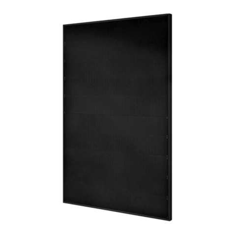
Perlight Solar IRT User manual

Perlight Solar
IRT Integrated Roof Tile
Installation Manual

Perlight Solar IRT Integrated Roof Tile Installation Manual 2www.perlight.com
V.03.2021 C2.6
Table of Contents
1. Introduction .....................................................................3
2. Class Application .........................................................3
3. Applicable Modules ....................................................3
4. Warning and Notes .....................................................4
5. Permit ................................................................................5
6. Climate Condition ........................................................5
7. Module Structure ..........................................................5
8. Mounting and Notes ........................................... 6-19
9. Module Wiring ............................................................20
10. Maintenance ...............................................................21
11. Recycling ......................................................................22

Perlight Solar IRT Integrated Roof Tile Installation Manual 3www.perlight.com
V.03.2021 C2.6
1. Introduction
Perlight Solar modules consist of a series of electrically interconnected crystalline silicon
solar cells, which are permanently encapsulated between a tempered glass superstrate and
substrate. The entire laminate is secured within an anodized aluminium frame for structural
strength; ease of installation and to protect the cells from the most severe environmental
conditions. Perlight Solar modules are a highly reliable, virtually maintenance-free direct
current (DC) power source, designed to operate eiciently in sunlight.
The Perlight Integrated Roof Tile (IRT) can be used directly as a roof tile and can cut roofing
costs by reducing the number of traditional roof tiles needed. The design of Perlight IRT is
dierent from other BIPV designs in the industry. The module is waterproof due to its physical
structure. No other chemical compound such as rubber are used to seal the module to make
it waterproof, which reduces the risk of water leakage caused by compound aging. The colour
of Perlight IRT is mainly black, to blend in with the roof appearance. Installation of Perlight IRT
is very convenient in comparison to other products with the same functionality, the number of
fittings installed is reduced by more than 50%.
Please read this manual carefully prior to handling and installation.
Installation and maintenance of Perlight Solar modules may only be carried out by trained and
qualified personnel. If you require further information, contact your supplier or local Perlight
Service Centre.
Please provide a copy of this manual to the owner and operator of the PV system for
reference.
Thank you for choosing Perlight IRT modules.
2. Class Application
The modules are qualified for application class A: Hazardous voltage (IEC 61730: higher than
50V DC; EN 61730: higher than 120V), hazardous power applications (higher than 240W)
where general contact access is anticipated (Modules qualified for safety through EN IEC
61730-1 and -2 within this application class are considered to meet the requirements for
Safety Class II).
3. Applicable Modules
This installation manual is applicable to the following modules:
24 cells: PLM-***M-24 (*** = 110-125)
24 cells: PLM-***MA-24 (*** = 110-125)
24 cells: PLM-***MB-24 (*** = 110-125)
*** represents module Wp in increments of 5W of figures shown.

Perlight Solar IRT Integrated Roof Tile Installation Manual 4www.perlight.com
V.03.2021 C2.6
4. Warning and Notes
Perlight Solar modules generate electricity when exposed to light. An array
of modules can cause lethal shock and burn hazards. Only authorized and
trained personnel should have access to the PV modules. To reduce the risk
of electrical shock or burns, modules may be covered with an opaque material
during installation. Do not touch live terminals with bare hands. Use insulated
tools for electrical connections.
Each Perlight Solar module has a pair of male and female waterproof connectors. For a series
electrical connection, connect positive (+) connector of first solar module to negative (-)
connector of the following module.
Do not short the positive and the negative. Do not disconnect under load. Ensure each
connection is sound with no gap between the insulators. Poor connections may cause arcing
and pose a fire and/or an electrical shock hazard.
Artificially concentrated sunlight shall not be directed on the Perlight Solar module. The
electrical characteristics are the indicated value of Pmax under standard test conditions
(Irradiance of 1000W/m, AM 1.5 spectrum, and cell temperature of 25°C).
Under normal conditions, a solar PV module is likely to experience conditions that produce
more current and/or voltage than reported at standard test conditions. Accordingly the
value of Isc and Voc marked on this module should be multiplied by a factor of 1.25 when
determining component voltage ratings, conductor current ratings, fuse sizes, and sizes
of controls connected to the Perlight Solar PV module output. Refer to local and national
Electrical Code for any additional multiplying factors, which may also be applicable.
Handle with care
Unpack and handle the PV modules with care. For safety always avoid installing PV modules
during wet and windy conditions or during electrical storms.
• Do not place heavy objects on to the PV modules.
• Do not step or walk on the module, although Perlight Solar modules are rugged, flexing
caused by bodyweight on the module face can create micro-cracks in the solar cells,
which may not be visible but will eect cell performance as the module ages. Take care
not to impact the module during installation, module glass can be broken (and the module
will no longer work properly) if it is dropped or hit by tools or other objects.
• Take care not to allow the front glass or backsheet of the module come into contact with
hard or sharp surfaces such as scaold during the installation process to avoid scratching
or damaging the PV module.
• Do not scratch the PV module backsheet.
• Do not drill or cut the PV module frame.
• Do not apply paint or glue to the PV module.

Perlight Solar IRT Integrated Roof Tile Installation Manual 5www.perlight.com
V.03.2021 C2.6
5. Permit
Before installing your system, contact local authorities to determine the necessary permit,
installation and inspection requirements.
6. Climate Conditions
Install the Perlight Solar PV modules in the following conditions:
• Ambient temperature: -20°C to +40°C.
• Operating temperature: -40°C to +85°C.
• Storage temperature: -40°C to +40°C
• Humidity: below 85RH%
• Max. static load front (Snow): 5400Pa
• Max. static load back (Wind): 3420Pa (Partial safety factor: 1.44)
• Corrosion resistant: Except for corrosive salt areas and sulphurous areas.
7. Module Structure
Fig.1: Module Structure
701mm
1036mm

Perlight Solar IRT Integrated Roof Tile Installation Manual 6www.perlight.com
V.03.2021 C2.6
8. Mounting and Notes
Identification of Left side, Right side and Middle modules.
Take care to identify the modules correctly. Outer module frames are designed to fit with the
surrounding flashing and cannot be interchanged.
The design of the outer left and outer right frames of Left & Right modules is
dierent from that of the Middle modules.
Outer left and right frames of Left & Right modules connect to the flashing system.
Note: The module Upper Frame is essentially the same as the Bottom Edge (2-1) mounting strip.
IRT Frame details
Upper Frame:
All modules
Lower Frame:
All modules
Flashing Edge:
Left & Right
Modules Only
Female Edge:
Left & Middle
Modules Only
Male Edge:
Middle & Right
Modules Only
Material: 6063-T5
PLM-***MB-24 (L)
Left (1-1)
PLM-***MB-24 (M)
Middle (1-2)
PLM-***MB-24 (R)
Right (1-3)

Perlight Solar IRT Integrated Roof Tile Installation Manual 7www.perlight.com
V.03.2021 C2.6
Illustration
Name Seal Strip 02
Side Flashing to Tile
Seal Strip 01
Aixed to Upper Frame
between panel rows
Mid-Clamp Left
2pcs on 1st module of each
row
Mid-Clamp Right
2pcs on every module
Material EPDM EPDM Stainless Steel Stainless Steel
Part No. 2-5 2-6 2-7 2-8
Fittings List
Illustration
Name Bottom Edge
Self-Tapping Fixing
5*30mm
For IRT & Mid-clamp
Self-Tapping Fixing
5*70mm**
For Wooden Batten
BS5534 Graded
Wooden Batten**
50*25mm
Material 6063-T5 Galvanised Steel Galvanised Steel Timber
Part No. 2-1 2-2 2-3 2-4
**Self-Tapping Fixing 5*70mm (2-3) & Wooden Batten (2-4) not included in kit

Perlight Solar IRT Integrated Roof Tile Installation Manual 8www.perlight.com
V.03.2021 C2.6
No. Position Shape Part No.
1 Flashing–Top Mid 3-1
2 Flashing-Top Left 3-2
3 Flashing-Top Right
(symmetrical to 3-2, and
has the same function)
3-3
4 Flashing - Side Left 3-4
5 Flashing - Side Right
(symmetrical to 3-4, and
has the same function)
3-5
6 Flashing - Bottom 3-6
7Seal Strip 03 –
Used under Bottom
Flashing & Over Top
Flashings.
3-7
Flashing Components

Perlight Solar IRT Integrated Roof Tile Installation Manual 9www.perlight.com
V.03.2021 C2.6
Installation Steps (Example)
Calculate installation position of IRT modules
Four battens required per row.
Supporting Bottom Edge & top anchor positions in Upper Frame and
approxamatley 259mm from module ends.
Existing roofs:
Remove Battens/Laths from IRT Junction Box position to avoid contact with Junction box.
IMPORTANT:
For wind-loading safety all 50*25mm wooden battens
must be fixed using 5*70mm wood screws.
998mm
Approx.
332mm
Approx.
332mm
Approx.
332mm
150mm
50*25mm Wooden Batten (2-4) spacing required is 998mm between
Bottom Edge (2-1) position & top of module anchor position of the
Upper Frame.
Two supporting 50*25mm Wooden Battens are placed between these
battens, leaving approxamatley 332mm space between each batten.
Spacing is repeated on every subsequent row using the lower row anchor
position in place of Bottom Edge position.
Install the modules left-to-right, starting with the bottom row.
Complete the installation of each row before beginning the row
above.
Note: The first row of tiles beneath the array must be in place
before beginning installation.
Install Seal Strip 03 (3-7). The top of the Seal Strip 03 will cover
the bottom batten and provide a waterproof barrier between the
array and first row of tiles. The Seal Strip 03 should be formed
with care on top of the first row of tiles below. Allow 150mm -
200mm overrun after each end of the bottom batten. This will be
covered later by the side flashings.
Caution: Correct alignment of Flashing-Bottom & Bottom
Edge is a critical step of installation, take extra care to ensure
correct alignment.
Install Flashing-Bottom (3-6) & Bottom Edge (2-1)
Align both Flashing-Bottom & Bottom Edge with the top of the
bottom batten.
Use the Self-Tapping Fixings 5*30mm (2-2) to secure both into
position.

Perlight Solar IRT Integrated Roof Tile Installation Manual 10 www.perlight.com
V.03.2021 C2.6
Installation Steps (Example)
Placement of the First Module
Once the Bottom Edge and Flashing-Bottom is installed, installation of the modules can begin.
Installing bottom row of modules:
The Lower Frame of the module (Grey) slots into the Bottom Edge
(Yellow) as illustrated.
Always begin IRT installation from the bottom left.
Complete the row from left to right before beginning installation of the row above.
Remember to only use:
PLM-**MB-24 (L) for the leftmost module of each row.
PLM-**MB-24 (R) for the rightmost module of each row.
PLM-**MB-24 (M) for every module between Left & Right end modules.
Continue to install the remaining Flashing-Bottom & Bottom
Edges ensuring they are level and aligned with the previous ones.
Note that all Bottom Edges must be aligned with each other in
a uniform line so that the subsequent modules can be aligned.

Perlight Solar IRT Integrated Roof Tile Installation Manual 11 www.perlight.com
V.03.2021 C2.6
Installation Steps (Example)
Placement of the First Module
1st Module of
each row only
Install on
every module
Begin module installation with
PLM-**MB-24 (L) (1-1).
Slot the Lower Frame into the Bottom Edge. Fine
tune the position of module to keep the centre of the
module and the centre of Bottom Edge consistent.
The Upper Frame of the module needs to be fixed with
Self-Tapping Fixings 5*30mm (2-2) after it is put in
place.
Fit module Mid-Clamps: Left (2-7) & Right (2-8) to
first module.
1. Slide the module Mid-Clamp into the rear of the
module frame.
2. Slide down, locking into postion onto the supporting
and screw to secure using Self-Tapping Fixing
5*30mm (2-2).
Only the first module of each row requires two of
both Left & Right Mid-Clamps.
Every other module requires two Right Mid-Clamp
(2-8) only.
Left side Mid-Clamps (2-7) Right side Mid-Clamps (2-8)

Perlight Solar IRT Integrated Roof Tile Installation Manual 12 www.perlight.com
V.03.2021 C2.6
Installation Steps (Example)
Placement of additional modules
After the first module (1-1) is fixed, you can continue to
install the next module of the same row.
PLM-**MB-24 (M) (1-2) should be used in the middle
section only.
Note that when the end of the row is reached, the
rightmost module must be PLM-**MB-24 (R) (1-3).
We suggest that two installers carry the module
by holding two sides. Insert the Male Edge of the
second module into the Female Edge of the first
module as shown in the picture.
At the same time, lock the Lower Frame of this
module with the clamp slot of the Bottom Edge.
Lay the module down and slide down into position.
Check the placement to make sure the whole frame
is in place and the module is placed flat. Because the
frame will slide down naturally, there may still be room
between Lower Frame and Bottom Edge slot, and
slight mismatches between the second module and
the first module as shown in the picture. Pull down the
second module to make the Lower Frame insert into
the Bottom Edge slot.
To ensure alignment of the upper and lower parts of
joining modules, a rubber hammer can be used to tap
the Upper Frame of the module. Use a wooded strip
with equal length to the module against the module
edge and gently tap into final position. Do not strike
with excessive force and do not strike the front
side of the module.

Perlight Solar IRT Integrated Roof Tile Installation Manual 13 www.perlight.com
V.03.2021 C2.6
The waterproof and drainage function of the modules
can be achieved only when the Male & Female Edges
are tightly connected.
There can be no dislocation in order to protect the
waterproof and drainage function.
There are three slots to lock the modules. Please lock
the module in the first slot. The module can be locked in
the second slot and maintain waterproof and drainage
function but if the module is locked in the third slot, there
will be a risk of leakage. See below.
Installation Steps (Example)
Waterproofing and Drainage
After the module is in the place, fix it with 5*30mm Self-Tapping Fixings (2-2) the same as the
first module.
When installing the rightmost side, pay attention to using the PLM-**MB-24 (R) (1-3), so that
the rightmost modules can be connected to the Flashing-Side Right (3-4).
Illustration
Warning
Lock in the first slot,
for best waterproof and
drainage function.
Lock in the second slot,
to basically meet the
requirements.
Avoid locking in the
third slot, there will be
a risk of leakage.

Perlight Solar IRT Integrated Roof Tile Installation Manual 14 www.perlight.com
V.03.2021 C2.6
Installation Steps (Example)
Installing Seal Strip 01 after completion of first row
After the installation of the first row of modules is
complete, Seal Strip 01 (2-6) is uniformly placed at
the slot of the aluminium Upper Frame of the modules
that runs below the anchor points.
Seal Strip 01 is placed from the first module to the last
module, forming a complete waterproof line.
Seal Strip 01 must run continuously without any
brakes.

Perlight Solar IRT Integrated Roof Tile Installation Manual 15 www.perlight.com
V.03.2021 C2.6
The module Lower Frame slots directly into the Upper
Frame of the module in below row.
Remember when installing the first module in each
row, PLM-**MB-24 (L) (1-1) must be used.
The figure on the left shows the Lower Frame of the
module (Blue) slotting into the Upper Frame (Yellow)
of the already installed module and Seal Strip 01 (2-6)
(Red).
Due to the installation of Seal Strip 01 (2-6), it may
be diicult to pull down the module after placement.
To ensure alignment of the upper and lower joining
modules, rubber hammer can be used to tap the
upper edge of the module. Use a wooded strip with
equal length to the module against the Upper Frame
and gently tap into final position. Do not strike with
excessive force and do not strike the front side of
the module. Use Self-Tapping Fixings 5*30mm (2-2)
to lock modules tightly after placement & follow the
same steps to add Mid-Clamps as in the first row.
The installation of middle modules in each row is the
same.
Also note the final module of the row must be PLM-
**MB-24 (R) (1-3).
The process is completed the same as the bottom row
including installation of Seal Strip 01 (2-6).
Installation Steps (Example)
Installing modules above bottom row

Perlight Solar IRT Integrated Roof Tile Installation Manual 16 www.perlight.com
V.03.2021 C2.6
Installation Steps (Example)
Side Flashing installation
Flashing-Left (3-4) & Flashing Right (3-5) are symmetrically
designed and are matched with PLM-**MB-24 (L) (1-1) & PLM-
**MB-24 (R) (1-3) Flashing Edges. Flashing-Left & Flashing Right
slide into the outer Flashing Edges of PLM-**MB-24 (L) & PLM-
**MB-24 (R) Flashing Edges from the bottom.
Begin with the bottom row and work upwards.
Installation of the second row flashing:
The installation of second row flashing is the same as the first, both
slide into the module outer Flashing Edges. A partial lower area of
the second flashing covers the first to form an overlapping area.
Side Flashings are designed for the upper flashing to overlap
the lower Flashing.
After Flashing-Left and Flashing-Right are all installed, attach Seal
Strip 02 (2-5) to the flashing.
Seal Strip 02 can be cut later, when laying roof tiles to fill any gap
between the roof tiles & flashing as shown.

Perlight Solar IRT Integrated Roof Tile Installation Manual 17 www.perlight.com
V.03.2021 C2.6
Installation Steps (Example)
Installation of Top flashings
Installation of the top flashings uses three types of flashing: Flashing-Top Mid (3-1), Flashing-Top Left (3-2),
and Flashing-Top Right (3-3), which can be installed from Left to Right or Right to Left.
Start with one corner, then install the Flashing-Top Mid (3-1) before installing the opposite corner.
All three types have the same structure as the clamping parts of the module Lower Frames. The Flashing-Top
Left (3-2) and Flashing-Top Right (3-3) are symmetrical in shape, and the installation method and function are
the same. Compared with the Flashing-Top (3-1), the left and right virticle extension parts are added, which are
inserted into the Flashing-Side Left (3-4) and the Flashing-Side Right (3-5) of the system to form an overlapping
water drainage path.
Each Top flashing has a profile, which is similar in shape and size to
the profile of the module Lower Frame and connects in the same way
to the Upper Frame of the modules in the top row of the array.
The illustration on the left shows how the Top flashings clamp to the
module Upper Frame.
The virticle extension of the Flashing Top-Left & Top-Right, slide
into the side flashings as shown in the figure on the left. Top-Left &
Top-Right flashings overlap the side flashings to create a drainage
channel.

Perlight Solar IRT Integrated Roof Tile Installation Manual 18 www.perlight.com
V.03.2021 C2.6
Laying Tiles
Perlight IRT can be connected with dierent types of tiles, including flat tiles and corrugated tiles.
Ensure the Seal Strip 02 is fully filling any gaps in the tiles at the side of the array. Seal Strip 02 may be cut
to fit the profile of the tile depending on tile type.
Finally, lay the first row of tiles above the array ensuring the tiles do not protrude over the modules.
Allow each Top flashing to overlap between 20mm-30mm.
After completing the Top Mid, Top-Left & Top-Right Flashings
installation, install Seal Strip 03 (3-7) to ensure watertightness
and leave up to 10mm of Top-Flashing uncovered as shown in the
illustration.

Perlight Solar IRT Integrated Roof Tile Installation Manual 19 www.perlight.com
V.03.2021 C2.6
Installation Example

Perlight Solar IRT Integrated Roof Tile Installation Manual 20 www.perlight.com
V.03.2021 C2.6
9. Module Wiring
Each solar module is wired with three separate series cell strings.
Bypass Diodes
Bypass diodes are wired in parallel with the series cell strings to prevent hot spot heating
caused by individual cell reverse bias that occurs when a module is partially shaded.
Output Cables
Each module has two standard 90°C rated, water-proof, UV resistant output cables each
terminated with plug & play connectors. This cable is suitable for applications where wiring is
exposed to the direct rays of the Sun.
Field connections
Connecting cables should be a minimum of 12 AWG copper cables, which are UV resistant
and insulated for a minimum of 90°C. All wiring and electrical connections must comply with
local and national Electrical Code.
Blocking Diodes
In a system utilizing a battery, blocking diodes are typically placed between the battery
and the solar module output to prevent battery discharge at night. Diodes that are used as
blocking diodes must: Have a Rated Average Forward Current [IF(AV)] above maximum
system current at highest module operating temperature. Have a Rated Repetitive Peak
Reverse Voltage [VRRM] above maximum system voltage at lowest module operating
temperature.
Table of contents
Other Perlight Solar Inverter manuals
Popular Inverter manuals by other brands

Champion
Champion 100306 Operator's manual

Veichi
Veichi AC10 Series Technical manual

WEG
WEG CFW501 V1.8X Programming manual

Afore
Afore HNS3000TL Installation and operation manual

ExelTech
ExelTech XP250 Installation and operation manual

EnerSys
EnerSys OutBack Power Rapid Shutdown Initiator quick start guide

SMA Regelsysteme GmbH
SMA Regelsysteme GmbH Sunny Boy 2800i installation guide

nord
nord NORDAC SK 700E manual

Xantrex
Xantrex Xantrex PRO XM 1000 owner's guide

Solar Stik
Solar Stik 24VDC PRO-VERTER 7000-120 AGS Operator and maintenance manual

SolaX Power
SolaX Power X3-MEGA G2 Series Quick installation guide

ABB
ABB PVI-GSM/GPRS Quick installation guide