Perten DA 7440 User manual

DA 7440 User Manual v.1.1 Aug 2015
1 (48)
DA 7440
User Manual

DA 7440 User Manual v.1.1 Aug 2015
2 (48)
(Intentionally blank)

DA 7440 User Manual v.1.1 Aug 2015
3 (48)
1. Safety Instructions
Warning:
The DA 7440 sensor must not be in direct contact with anything combustible.
Warning:
To prevent operator injury or damage to the apparatus, verify that the
instrument is connected to protection ground before turning on main power.
Caution:
Protecting the PC from virus, trojans and other malware is the responsibility of
the customer. The PC as supplied does not contain any anti-virus protection.
Should it be a wish to install antivirus software, Perten can be of assistance, but
cannot assume responsibility for any system malfunction, should the selected
software conflict or otherwise cause difficulties.
Caution:
Instrument commissioning, replacement or service of components within the
instrument is to be performed by qualified personnel only.

DA 7440 User Manual v.1.1 Aug 2015
4 (48)
2. General description
2.1 Introduction
The DA 7440 on-line analyzer represents a new generation Diode Array Technology based NIR
over-the-belt measurement type systems. The analyzer provides real time information about the
product as it is being produced, enabling fast automatic process control, full traceability and
allowance of immediate manual intervention. The DA 7440 is built on the latest technology,
designed for high performance and software including a number of new features.
2.2 System features overview
The DA 7440 is designed to measure on-line on a wide range of products passing under the
measurement sensor as they are conveyed through a process. The instrument is designed to be
easy to use, robust and to require a minimum of regular maintenance in the demanding plant
environment.
The DA 7440 On-Line uses Diode Array technology and typically collects complete sample
measurements more than 30 times per second. The spectrometer is free from moving parts and
uses an array of 256 InGaAs detectors, providing spectra in the region 950 to 1650 nm.
Continuous wavelength stabilization and automatic internal reference ensures accurate
measurements, stability over time and calibration transferability between DA 7440 on-line
instruments. The spectrometer design is similar to the Perten DA 7250 NIR at-line - and DA
7300 in-line analysers allowing for calibration transferability from these instruments as well.
The DA 7440 system consists of the following parts:
- DA 7440 NIR Sensor
- At-line display
- Junction box with PC
Optional are modules for:
- Extended communications
The optional modules are
connectable to the Junction box.
Communication between the
system parts is made over
Ethernet, either connected to
network or through wireless
interface. Compressed air
supplied to the sensor is used by
an air-purge system to keep the
measurement window clean.

DA 7440 User Manual v.1.1 Aug 2015
5 (48)
2.3 Copyright and liability
Copyright
Perten Instruments AB reserves all rights to this document. It may not be copied, reprinted or
disclosed either fully or in part to a third part without the written consent by Perten Instruments
AB.
Liability
The recommendations and suggestions regarding the product and use that are offered by Perten
Instruments, in our information material, or information provided by any employee, broker, or
distributor of Perten Instruments, are a guide in the use of this product and are not a guarantee
to their performance since Perten Instruments has no control over its use. In no event shall
Perten Instruments, or its affiliates be liable for indirect, incidental, or consequential damages of
any nature including, but not limited to, loss of profits, revenue, production, or use, business
interruption, in the use or performance of any Perten Instruments product. Perten Instruments,
or its affiliates' total aggregate liability for damages of any nature, regardless of form of action,
shall in no event exceed the amount paid by you to Perten Instruments, or its affiliates for the
product upon which liability is based.
2.4 Declaration of conformity
Manufacturer: Perten Instruments AB
Address: P.O. Box 9006
SE-126 09 Hägersten, SWEDEN
Declare that the product: DA 7440 Complies with the CE directives and requirements stated
below:
LVD directive 2006/95/EC
EN 61010-1:2010 (Electrical equipment for measurement, control and laboratory use.)
General requirements
EN 61010-2-081:2002/a1:2003 (Particular requirements for automatic and semiautomatic
laboratory equipment for analysis and other purposes)
EMC directive 2004/108/EC
EN 61326-1:2006 (Electrical equipment for measurement, control and laboratory use –
EMC requirements.)
In addition requirements for the US & Canada
UL61010-1, 2012 Third edition / CAN/CSA C22.2 No. 61010-1, 2012 Third edition
FCC part 15 subpart B, class B (2010)

DA 7440 User Manual v.1.1 Aug 2015
6 (48)
3. Table of contents
1. Safety Instructions.............................................................................................................3
2. General description ...........................................................................................................4
2.1 Introduction .......................................................................................................................................4
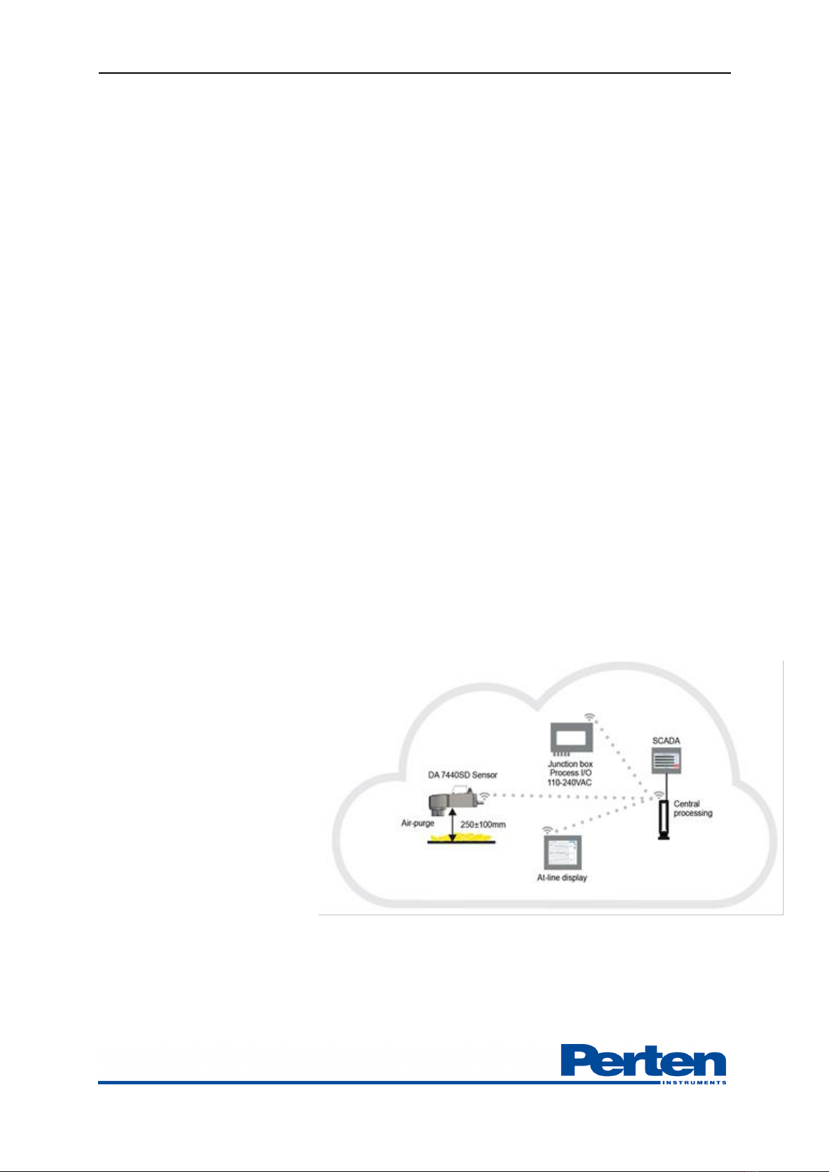
2.2 System features overview .................................................................................................................4
2.3 Copyright and liability.......................................................................................................................5
2.4 Declaration of conformity................................................................................................................5
3. Table of contents...............................................................................................................6
4. Setting up the instrument .................................................................................................8
4.1 Environmental conditions................................................................................................................8
4.2 Overview of installation pre-requisites...........................................................................................8
4.3 DA 7440 NIR Sensor .......................................................................................................................9
4.4 Junction box and instrument PC...................................................................................................10
4.5 At line display...................................................................................................................................10
4.6 Network set-up................................................................................................................................11
5. Process Plus Operational Overview ...............................................................................................12
5.1 Overview...........................................................................................................................................12
5.2 Logging in.........................................................................................................................................12
5.3 View measurement results..............................................................................................................13
5.4 Select product setting to use ..........................................................................................................15
5.5 Following measurement trends .....................................................................................................15
5.7 Grab sample collection...................................................................................................................18
6. Measurement set-up........................................................................................................20
6.1 Overview Setting menu ..................................................................................................................20
6.2 Analysis Profiles settings ................................................................................................................21
6.3 Sample collection settings ..............................................................................................................23
6.4 Bias adjustment................................................................................................................................23
7. Reporting and Data export .............................................................................................24
7.1 Data export overview......................................................................................................................24
7.2 Exporting grab samples results and corresponding measurement spectra.............................25
7.4 Exporting measurement results.....................................................................................................27
7.4 Exporting measurement spectra....................................................................................................27
7.3 Batch reports....................................................................................................................................28
8. Maintenance....................................................................................................................30
8.1 DA 7440 Maintenance overview...................................................................................................30
8.2 Maintenance checklist.....................................................................................................................30
8.3 Instrument cleaning.........................................................................................................................31
8.4 Replacing the lamp..........................................................................................................................32
8.5 External check sample ....................................................................................................................35
8.6 Spare parts list..................................................................................................................................37
9. Extended configuration ..................................................................................................38
9.1 Connecting DA 7440 sensor..........................................................................................................38
9.2 DA 7440 sensor IP configuration.................................................................................................39
9.3 Product Detection...........................................................................................................................40
9.4 Product Movement Detection.......................................................................................................41
9.5 Updating Calibration models.........................................................................................................42
9.6 Integration of measurement results ..............................................................................................43

DA 7440 User Manual v.1.1 Aug 2015
7 (48)
10. Troubleshooting ............................................................................................................43
10.1 Instrument status overview..........................................................................................................43
10.2 Communication error ...................................................................................................................45
11. Technical specifications ................................................................................................46

DA 7440 User Manual v.1.1 Aug 2015
8 (48)
4. Setting up the instrument
4.1 Environmental conditions
Temperature
Ambient temperature specifications: 0°C - 40°C. Humidity 50% RH ±30%
Light protection
The measurement spot shall be protected from intense stray light. Sensor must not be placed in
direct sunlight or under strong light varying in intensity.
Mechanical protection and interface
Measurement sensor and cabinet must not be covered with anything in direct contact to the
apparatus.
Explosive environment
The sensor, PC, cabinet or at-line displays must not be placed in explosive environment.
4.2 Overview of installation pre-requisites
The DA 7440 Sensor is designed to measure at a distance of 250 mm above a moving product.
Measurement light spot is illuminated and measurements shall be made on the product within
illuminated area. Avoid installation exactly parallel to the conveyor belt if there is a risk of gloss
reflection coming from the conveyor belt surface. If the surface is glossy, install with angle ±5º
from 90º. Illumination could heat up the product, hence measurements should be on a moving
product only. The Sensor is equipped with an Air-purge keeping the sensor window clean and
free from dust or dirt.
The following pre-requites are needed for installation:
-Mounting Bar, 38 mm diameter, to place the sensor 250 mm above the moving product.
-Prepared location for placement of Junction box, PC and At-line display
-Power: 230 V AC 50-60 Hz (To electronics cabinet, 24 V DC to sensor provided by cabinet).
-Network : TCP/IP 100/100 Mbps network .
-Compressed air: 4 bar. The connector should be a 6 mm in diameter tube. The maximum flow
rate needed should be 60 liter/min.

DA 7440 User Manual v.1.1 Aug 2015
9 (48)
4.3 DA 7440 NIR Sensor
Front and rear of instrument, overview of key parts and dimensions.
Front of instrument:
Rear of instrument:
Power inlet connection:
Connecting side Face side
Removable Air purge funnel
Lid for Lamp replacement
Connection Box
Handle and holder for
mounting bar
Light tower for instrument
status indication. Wi-Fi antenna
Main power inlet
Ethernet connection
Compressed air inlet
Protective earthing connection
Pin 1 +24VDC (red)
Pin 2 - / ground (black)
Pin 3 - / ground (Brown)
Pin 4 +24VDC (orange)

DA 7440 User Manual v.1.1 Aug 2015
10 (48)
Instrument dimensions:
4.4 Junction box and instrument PC
To ease the DA 7440 instrument installation, a junction box for electronics could be included in
the scope of supply. The junction box should be placed in close vicinity of the sensor. It includes:
- 24 V DC power supply with UPS
- 4 port router with wireless access point
- PC
- Optional gateways for Analogue output and Fieldbus interfaces
The PC runs the operating software ProcessPlus on a Windows 7 platform. This computer is
placed in the junction box or optionally in a server room. As an alternative of using the Perten
supplied dedicated PC, the Process Plus software can be installed on a partition in a server.
Anti-virus protection is the responsibility of the instrument user. The PC does not include any
anti-virus software.
4.5 At line display
Enhancing the functionality of the instrument,
one optional At-line display is included in the
scope of supply. The screen provides at-a-glance
information of actual measurements in graphical
or numerical form. The instrument status is
shown with signaling and status messages,
highlighting the current instrument status.
The touch screen can also be used for taking the
grab samples. The At-line display is typically
placed in close connection (a few meters) to the
DA 7440 sensor measurement position.
Communication to the display is made through
Ethernet cable or wireless.

DA 7440 User Manual v.1.1 Aug 2015
11 (48)
4.6 Network set-up
The DA 7440 system parts are communicating through TCP/IP network. It is recommended
that the system parts are connected using static IP addresses or to a Dynamic Host Configuration
Protocol (DHCP) server that can give IP addresses on long term lease. The DA 7440 Instrument
PC and sensor are by default configured with static IP addresses. Instrument PC default IP
address is 192.168.1.3. DA 7440 sensor default IP address is 192.168.1.5.
See chapter 9.1 for further information on network configuration.

DA 7440 User Manual v.1.1 Aug 2015
12 (48)
5. Process Plus Operational Overview
5.1 Overview
The DA 7440 On-Line runs on a Windows 7 operating platform. The Process Plus software
operates and is the graphical interface for Perten Process Instruments. Measurement results can
be observed, production trends followed and validation samples collected.
The user interface is web-based, meaning that any user can access real-time measurement
information from a web-browser on a computer or tablet anywhere on the network. The access
can be made without requiring additional software to be installed. For example, whilst the
operator is using the At-line display, the Production Manager can view measurements in his
office in real time. The laboratory technician can, simultaneously and independently, add
reference analysis results to the manual sampling report, allowing a quick and continues
verification of sensor performance.
In the event that there are multiple sensor installed in a factory, the results from each sensor is
displayed using different web browser tabs on the same computer.
The software measures with high speed and automatic filtering, allowing accurate
measurements on inhomogeneous product or interrupted product flows. Filtering times and
update intervals can be tuned to follow the variations in the production process in an optimal
way.
5.2 Logging in
Process Plus graphical interface is web based and accessible through web browser on computer,
tablet or smart phone. Recommended browser is Google Chrome.
To access the Process Plus interface, enter the IP-address of the instrument in browser field.
Providing the network is set-up to allow for computer name translation to IP-address, the login
can be done using instrument computer name instead of the IP address.

DA 7440 User Manual v.1.1 Aug 2015
13 (48)
5.3 View measurement results
When logged on to the system the main interface screen, Results, will be shown with current
measurement values. Measurements will update according to set interval.
The picture below show a typical interface screen, with product and measurement results.
Number of parameters shown are edited in Display settings.
A profile can include up to 20 parameters, select the number to display among the parameters in
the profile with drop down Max Results box.
Instrument IP adress
Product
Parameter and current
measurement
Profile selection
Activate
sample
collection
Display
settings
Tools and
settings
Show trend
charts
Show grab
samples
collected
Show batch
reports
Process Plus
version, time
of
measurement
update

DA 7440 User Manual v.1.1 Aug 2015
14 (48)
If Targets and alarm levels are activated, displayed values will be shown together with indicator if
parameters is measured within specifications. Green indicates within specification, yellow on
warning limit and red out of upper or lower specification. See chapter 6.2 for setting levels.
Supporting remote maintenance, a live video from an accessory web camera can be viewed in
combination with displayed values. The web camera can be pointed at the conveyor belt
measurement spot, displaying the production status.

DA 7440 User Manual v.1.1 Aug 2015
15 (48)
5.4 Select product setting to use
Measurement calibrations and configurations for each product is set-up in Analysis Profiles. The
instrument is set-up to auto start on the last analysis profile in which measurements were done.
Changing of Analysis profile is done through Select profile button.
Select the Analysis profile which is to be used to measure. Measurements will auto start using the
selected profile, including the defined measurement settings.
Batches are separated based on when new products are activated. Re-selecting an active product
will create a new start- and stop batch time, on which summarized results can be displayed. Also
see chapter 7.3
5.5 Following measurement trends
Selecting the Trend Tab allows for following trends in the measurement results.
Current results are shown in combination with a graph displaying measurement trends.

DA 7440 User Manual v.1.1 Aug 2015
16 (48)
Selection in graph allows for zooming.
Exit zoom by pressing reverse symbol.
The graph is either auto scaling to follow the changes in each parameter or set to specific ranges
if these are defined. Alarms and Warning can be visualized to show when production is within
specifications.

DA 7440 User Manual v.1.1 Aug 2015
17 (48)
Setting the cursor in the graph displays a line and the measurement results at the selected time.
Number of parameters shown, displayed time period and statistics option are set in the Display
settings
Time span shown can be selected from drop down menu.
Number of parameters shown are selected from drop down menu. A profile can include and
display up to 20 parameters.

DA 7440 User Manual v.1.1 Aug 2015
18 (48)
Activating show statics tab allows for observing statcisics of measurement in current batch in the
trend chart
Average measurement result, standard deviation, minimum, maximum and range in current batch
is displayed.
Re-selecting the product or selecting a new product reactivates the statistics.
5.7 Grab sample collection
Measurement validation and calibration development is dependent on the collection of
production samples in close vicinity to the NIR process instrument. The matching and
observation of results from grab samples can be done in the Process Plus graphical interface.
When taking a sample, mark the corresponding measurement by pressing the Collect sample
button.
A window is shown indicating the results of the sampling. If data acquisition during the sampling
was successful, the sampling is acknowledged by the a message, Done

DA 7440 User Manual v.1.1 Aug 2015
19 (48)
The measurement profile can be set-up to include optional sample-id.
If not enough product was present or if instrument was running self-test during the sampling a
sampling Failed indication will be shown. Verify that product is present, unit is in measurement
mode Running and sample again.
Collected samples can be viewed by pressing Laboratory Samples tab.
Instrument measurement results of grab samples are given in NIR column. To facilitate
adjustments, validation and calibration development the grab sample results from laboratory
methods can be entered in LAB column. An extended Sample ID may also be entered
Pressing Date or Sample Id will sort on the respective column.

DA 7440 User Manual v.1.1 Aug 2015
20 (48)
Erratic sample collection can be removed with deletion button.
6. Measurement set-up
6.1 Overview Setting menu
Instrument settings are edited in Tools and settings –Settings menu.
Changing instrument settings requests an Administrator password. Contact your Perten
instruments office or local Perten instrument partner for obtaining the Administrator password.
Once signed in as Admin as sign in confirmation will be shown in interface. Press Sign out to exit
Admin log on.
Table of contents
Other Perten Measuring Instrument manuals