Pertronic SYSTEM SENSOR FL0111E Product manual

FIRE ALARM ASPIRATION SENSING TECHNOLOGY®
INSTALLATION AND MAINTENANCE GUIDE
STAND-ALONE FAAST LT : MODELS FL0111E, FL0112E AND FL0122E
© Pertronic Industries Ltd 1 FAAST LT Stand-Alone Installation & Maintenance Guide Iss 1.0, 201701
367 mm
135 mm
56 mm
44 mm
403 mm
356 mm
DESCRIPTION
The FAAST LT Series is part of the Fire Alarm
Aspiration Sensing Technology® (FAAST) family.
FAAST is an advanced fire detection system for use
where early warning and very early warning are a
requirement. The system continuously draws air from
the controlled environment through a series of sampling
holes to monitor the environment for smoke particulate.
The FL01 Series is the stand-alone (relay) version of
the FAAST LT range, connected with the Fire Panel or
other monitoring system using clean-contact relays.
The FL01nnE is available in 3 different models each, 6
models total:
FL0111E - has single channel capability with one
laser smoke detector.
FL0112E - has single channel capability with two
laser smoke detectors in a common
chamber for coincidence detection.
FL0122E - has two channel capability with two laser
smoke detectors in separate chambers,
one detector per channel.
This guide provides information for mounting and basic
installation using the unit’s default factory settings.
For more advanced information refer to:
I56-3888-001P FAAST LT PipeIQ Configuration Guide.
SPECIFICATIONS
Environmental Ratings
Temperature: -10oC to 55oC
Relative Humidity: 10% to 93% (non-cond)
IP Rating: IP65
Mechanical:
Exterior Dimensions: 403 x 356 x 135mm
Wiring: 0.5mm2to 2.0mm2max
Maximum Single Pipe Length: 100m
(Classes A, B & C)
Maximum Number of Holes: See Table 1A
Pipe Spec (EN54-20 Compliance): to EN61386
(Crush 1, Impact 1, Temp 31)
Outside Pipe Diameter: 25mm or 27mm (nom.)
Shipping Weight: 6.5kg (incl. detectors)
Colour Code Key: (refer to back page)
Black: applies to both FL01nn and FL20nn Series
Blue: refers to Important Settings which should be
verified
Figure 1: Dimensions and Knock-Outs
PARTS LIST
Description Quantity
FAAST LT Unit 1
Mounting Bracket 1
3-pin Terminal Block 6
4-pin Terminal Block 1
2-pin Terminal Block 3
47KΩEOL Resistor 2
USB Cable 1
Front Panel Labelling Pack 1
USB Memory Stick with documents 1
FAAST Carton Contents Guide 1
Important Note
Aspirating Smoke Detectors supplied and installed
within the EU must conform to the EU Construction
Products Directive (89/106/EEC) and the related
European Product Standard EN 54-20. FAAST LT has
been tested and certified to ensure that it conforms to
the necessary Standards, but strict adherence to this
instruction guide is advised to ensure that the
installation meets the requirements of the CPD
Directive.
Electrical Characteristics
Voltage Range: 18.5 - 31.5 VDC, Nominal = 24VDC
Supply Current: @ 24VDC, 25oC - excludes Sounders
1 Channel: 170mA (typ), 360mA (max)
2 Channel: 270mA (typ), 570mA (max)
Fan Speeds: Min = 1 Typ = 5 Max=10

© Pertronic Industries Ltd 2 FAAST LT Stand-Alone Installation & Maintenance Guide Iss 1.0, 201701
A
FAAST LT
HANGING LUGS
FIXING HOLE FIXING HOLE
USE FOR PLUMB-LINE
INDICATES CENTRE OF ASPIRATING PIPES
90 mm 99 mm
59
329
212 mm 144 mm
41
mm
mm
mm
*
*
POSITION OF BRACKET
PLUMB LINE
BASE OUTLINE
OUTER DIMENSION OF UNIT
Note: this equipment and all associated pipe work
must be installed in accordance with all relevant
codes and regulations.
Section A : PHYSICAL INSTALLATION
Front Panel Labels
The FAAST LT is shipped without the front panel labels
fitted. This allows the installer to select the language
required from the Front Panel Labelling Pack.
Figure 2 shows where to place the labels:
Figure 2: Front Panel Label Locations
When label A is in place, remove the protector from the
bottom of the clear cover to stick the cover down, as
shown in Figure 3:
Figure 3:
Remove backing
tape to stick cover
down
Cable Access
Knock out cable gland holes where required.
The location of the cable glands is shown in Figure 1,
represented by the icon:
Figure 4: How to Knock Out Cable Gland Holes
Mounting the FAAST LT to the Wall
Figure 5: Mounting Bracket
* Minimum clearance required from hinges to open door = 35 mm.
Figure 6: Fasten the mounting bracket to the wall

© Pertronic Industries Ltd 3 FAAST LT Stand-Alone Installation & Maintenance Guide Iss 1.0, 201701
99 mm
41
1
2
mm
90 mm
4
3
0.00
5
329 mm
6
7
8
9
1 2 3 4
5 6
Figure 7: Sequence (1 to 9) to Mount the Detector on
the Bracket
7a
7b
7c
7d
Pipe Hole Configuration
Figure 8 shows the pipe holes available on the unit.
Each unit has 2 pipe holes per channel (so if installing
a 1 channel unit, holes 3 and 4 do not function). Use
Table 1 to locate the holes required for the installation:
Figure 8: Pipe Holes
Table 1: Pipe Holes Used for Each FAAST LT Model
FAAST LT Model
Inlet Pipe Hole
Outlet Pipe Hole
FL0111E
1 & 2, or 1 OR 2
5
FL0112E
1 & 2, or 1 OR 2
6
FL0122E
Channel 1:
1 & 2, or 1 OR 2
5
Channel 2:
3 & 4 or 3 OR 4
6
Notes: a) Unused Pipe Holes MUST be kept sealed
b) Do NOT glue pipes into Pipe Holes
Table 1a: Maximum Number of Pipe Holes Allowed Per
Channel
All figures quoted using highest (Level 1) sensitivity.
CLASS
Pipe Length
(m)
Max Number of Holes per Channel
C
100
18: 10 x 2.5mm, 8 x 3mm
PLUS 3mm Non-Sensing End Hole
B
100
6: 4 x 4mm, 2 x 5mm
Including End Hole
A
100
2 x 6mm
PLUS 6mm Non-Sensing End Hole
A
80
3: 1 x 5mm, 2 x 6mm
Including End Hole

© Pertronic Industries Ltd 4 FAAST LT Stand-Alone Installation & Maintenance Guide Iss 1.0, 201701
1234567891
01
11
21
31415161718
1
2
3
4
5
6
SAMPLING AREA
SAMPLING AREA
CHANNEL 2FILTER
POWER AND
ALARM
CONNECTIONS
CHANNEL 1FILTER
USB PORT
SENSOR COVER
POSITION FOR TEST MAGNETPOSITION FOR TEST MAGNET
EARTH BAR
MOUNT
EARTH BAR
MOUNT
EARTH BAR
(OPTIONAL)
Pipe Installation
Figure 9: Pipe Installation
Wiring Installation
Power, Alarm and Control Connections
Figure 10: Inside the Detector
Exhaust Pipe
Notes: a) All wiring should comply with
local requirements and regulations.
b) Loop wiring must observe the
recommendations of the panel
manufacturer
Notes:
- use the PipeIQ BOM Report to order the Pipe components
required to assemble the system
- use the PipeIQ Pipe Layout Report to assemble the pipe layout
Important: follow the Pipe Layout report as closely as practical.
- ensure Pipe Lengths are correct
- ensure Sampling Point holes are drilled at the stated positions
- ensure Sampling Point Hole Size is as defined
The PipeIQ design is based upon the information provided to the designer - this is often incomplete and therefore
inaccurate.
If it is not practical to install the system as designed, stop work, record the issues taking care to measure the
changes required, then redesign the PipeIQ BEFORE proceeding
(Unequal Pressures)
(Equal Pressures)

© Pertronic Industries Ltd 5 FAAST LT Stand-Alone Installation & Maintenance Guide Iss 1.0, 201701
FL01nnE Stand-Alone Terminal Connections
Table 2: Wiring Terminal Designations
(Note - Terminals marked CH2 are only available on 2 channel models)
No
Function
Connector
1
Ext Power In +
Primary PSU
T1
2
Ext Power In -
3
Aux Power In +
Not Used in Default
4
Aux Power In -
5
NC
Alarm Relay
CH1
T2
6
C
7
NO
8
NC
Alarm Relay
CH2
T3
9
C
10
NO
11
NC
Fault Relay
CH1
T4
12
C
13
NO
14
NC
Fault Relay (AUX)
CH2
T5
15
C
16
NO
17
Sounder Output 1 -
47KΩ EOL Resistor
T6
18
Sounder Output 1 +
19
Sounder Output 2 -
47KΩ EOL Resistor
T7
20
Sounder Output 2 +
21
Configurable Input +
(Reset)
Default is Active
= Short-Circuit
(unsupervised)
T8
22
Configurable Input -
23
NC
Pre-Alarm Relay
CH1
T9
24
C
25
NO
26
NC
Pre-Alarm Relay
CH2
T10
27
C
28
NO
FAAST LT Conventional Interface (FAAST-LTIF): refer to 0734-FAAST LT Conventional Interface Installation
Note
Overview: allows stand-alone FAAST detectors to be
directly connected to Zone circuits of a Pertronic Loop
Responder, F16e or F4 conventional panel.
- Alarm and Defect conditions are signaled on the
conventional circuit
- Zone Reset resets the FAAST LT
Table 3: Relays Figure 12: FAAST LT Conventional Interface
RELAY
ACTION
NOTES
ALARM 1 or 2
Set ON when Alarm condition is met on a Channel
Default condition = Level 1.
Alarm state is Latched (default) –Manual
RESET is required to de-activate the relay
and LED
PRE-ALARM 1 or 2
Set ON when Pre-Alarm condition is met on a Channel
Default condition = Level 1
FAULT 1 or 2
When FAULT CONDITION on Ch1 or Ch2 or a common
FAULT occurs. Fault is also signalled when in Service
mode and when the device is unpowered
Fault state is not Latched (default)
SOUNDER 1 or 2
Set ON when a channel is in ALARM. Sounder 1
corresponds to Ch1 and Sounder 2 corresponds to Ch2
Set ON in ALARM (default)
Setting the Detector Addresses:
Sensor : the Sensor address is
set on rotary decade switches on
the rear of the Laser (7251)
detector. The sensors are located
under the Sensor Cover inside the
unit (see Figure 10). The Smoke
Detector section of Service (refer
to Page 9) shows how to remove
the sensors
Each aspiration channel uses a
Loop Address to report its Status
information to the FAAST
detector. The default Sensor
addresses, generally used with
Stand-Alone ASDs, are:
Channel 1 7251 = 01
Channel 2 7251 = 02
Module:
The Module address is set using
rotary decade address switches
located behind the door - rotate
the wheels to the desired address.
The selected address refers to
Channel 1; on 2 channel units the
device assigns the next (+1)
module address to Channel 2
automatically
Module = 01
Figure 11: Address Switches
X 10 X 1

© Pertronic Industries Ltd 6 FAAST LT Stand-Alone Installation & Maintenance Guide Iss 1.0, 201701
POWER UP
Using Default Settings
1. Connect a suitable 24VDC supply (eg Pertronic AUX24V/1.3PSU-BLK) to pins 1 and 2 on Terminal T1 (refer to
Table 2)
2. Check the voltage at the connector. Make sure it is within the required voltage range.
3. If the voltage is within the specified range, connect the power connector to the unit.
4. Close and secure the housing door; verify the fan starts up and air flows out of the exhaust port. The unit takes
1-3 minutes to initialise and stabilise in Normal mode.
Configuring Other Options
To change any of the default options, it will be necessary to connect the detector to a PC/laptop with the PipeIQ
software installed; see USB Connection section later in this guide for more information on this (and the FAAST LT
Advanced Setup and Control Guide).
EXTERNAL RESET
The default setting for the configurable external input is Device Reset (terminal block T8). A short circuit
connection between these terminals will cause the FAAST LT unit to perform a Reset.
FRONT PANEL
The front panel differs depending on which of the 6 x FAAST LT models is being installed - each is shown below.
The following information is displayed:
- Detector Status: Normal, Alarm, Fault or Isolate
- Alarm Level: Pre-Alarm and Alarm - available with FL01nn detectors
- Particulate Levels:; 1-9 - available with FL01nn detectors
Notes: Pre-Alarm and Alarm LEDs (Red) activate when the particulate level reaches the Particulate
Level (1-9) selected in PipeIQ. That is, if Pre-Alarm is selected at Level 2 and Alarm selected at
Level 5, The Red Pre-Alarm LED will activate when the Particulate Level 2 LED (Yellow)
activates and the Red Alarm LED will activate when the Particulate Level 5 LED (Yellow)
activates.
Rarely, if ever, will the particulate level reach Particulate Level 10, before the Alarm activates.
- Flow Level:
- Test, Reset and Disable Buttons:
Figure 13: Front Panel Display
FL01nnE Stand-Alone Detector:
13a: FL0111E 13b: FL0112E 13c: FL0122E
1 Channel Detector (1 Sensor) 1 Channel Detector (2 Sensors) 2 Channel Detector

© Pertronic Industries Ltd 7 FAAST LT Stand-Alone Installation & Maintenance Guide Iss 1.0, 201701
Table 4a: FL01nnE Stand-Alone Front Panel Indicators and Fault Descriptions
INDICATOR
ACTION
WARNING OR TROUBLE
COMMENT / ACTION
CHANNEL 1/2
ALARM
ON Red
(Set by panel)
Channel is in Alarm
(relay is set ON)
No Delay with Default setting
1 BLINK Green
When sensor is polled
Not when in Alarm
CHANNEL 1/2
PRE-ALARM
ON Yellow
Channel is in Pre-Alarm
(relay is set ON)
SMOKE LEVEL 1/2
ON Yellow
LED number indicates detector Alarm
level reached
Only numbers 1 –9 used
INITIALIZATION
ON
FAAST LT is initializing
FAULT
ON Yellow
Common or multiple Faults
1 Blink
Fault Delay
Default = 60secs
POWER
ON Green
FAAST LT is powered
POWER FAULT
ON Yellow
Low Power alert / High Power fault
Check the Power Supply voltage
CHANNEL FLOW
INDICATORS 1/2
ON Green
The LED indicates the Air Flow for a
channel:
- Centre = Normal flow
- Left = Low flow;
(-20% at extreme)
- Right = High flow;
(+20% at extreme)
On 2 channel unit:
Ch1 : Upper row
Ch2 : Lower row
LOW FLOW
ON
Low Flow fault
check filter;
check pipe network for blockages
SENSOR
1 Blink
Detector initialization Fault
Restart the device; replace the detector
2 Blinks
Detector communication fault
Check detector addresses and
installation; replace detector
ASPIRATOR
ON
Air Flow sensor fault
Try to restart device
1 Blink
Flow initialization fault
Check filter; check pipe network for
blockages; try to restart device
2 Blinks
Fan fault
Try to restart device
DRIFT
COMPENSATION
1 Blink
Drift Compensation, 1st Alert
Clean detector
2 Blinks
Drift Compensation, 2nd Alert
Clean detector
3 Blinks
Drift Compensation, limit warning
Detector needs urgent maintenance
TEMPERATURE
1 Blink
Low Temperature alert
Check the Air Flow temperature
2 Blinks
High Temperature alert
INPUT
1 Blink
External Input fault
Not used with default settings
DISABLE
1 Blink
Alarms, Faults & Alerts not reported
Returns to Maintenance then Normal
operation after 60min (default)
SYSTEM
1 Blink
Incorrect configuration
Flashes all FAULT LEDs; try to restart
device
2 Blinks
EEPROM fault
Check power supply voltage.
Try to restart device
3 Blinks
Real Time Clock (RTC) fault
RTC is corrupted or time reading failed
SOUNDER
1 Blink
Sounder fault
Check the sounder circuit and the EOL
FILTER
1 Blink
Filter alert at Set Date
No date set as default
HIGH FLOW
ON
High Flow fault
Check pipe network for breaks or leaks
When simultaneous Alerts/Faults occur on the same LED, priority order is:
ON (Highest), 1 blink, 2 blinks, 3 blinks (Lowest)

© Pertronic Industries Ltd 8 FAAST LT Stand-Alone Installation & Maintenance Guide Iss 1.0, 201701
2
3
1
3
4
5
6
2
1
ION
Front Panel Buttons
The front panel has three (3) user buttons:
TEST, RESET and DISABLE
These buttons are used to enter the pass-code which then
allows simple test functions to be performed.
Note: In Remote Maintenance and Service Mode these
buttons are disabled.
Table 5: Front Panel Buttons
BUTTON
NORMAL Mode
MAINTENANCE Mode
RESET
Press for 2s to start PASSWORD
PROCEDURE to enter
MAINTENANCE mode
Press for 2s to Reset latched Alarms, Faults
and sounders (relays).
In DISABLE Mode, press for 2s to exit from
DISABLE Mode (but remains in
MAINTENANCE Mode)
DISABLE
Use to increment Password digits in
PASSWORD PROCEDURE
Press for 2s to enter DISABLE Mode for 60
minutes (default).
Alarms, Alerts and Faults not reported
(To exit DISABLE Mode see RESET)
TEST
Use to confirm password in
PASSWORD PROCEDURE.
Default Password = 3111
Press for 2s then release - both detectors will
simulate Alarm
Press for 4s then release –Detector #1 will
simulate Alarm
Press for 6s then release –Detector #2 will
simulate Alarm
COMBINATIONS
RESET + DISABLE
Press for 2s to show Fan Speed (on
Smoke Level scales) for a preset time
Press for 2s to show Fan Speed (on Smoke
Level scales) for a preset time
RESET + TEST
No action
Press for 2s to turn Sounders OFF
RESET + TEST + DISABLE
No action
Press for 2s to exit MAINTENANCE mode
Password Sequence to Enter MAINTENANCE mode
a) press and hold RESET; Left Flow indicator turns yellow, then green
b) release RESET and FAULT indicator turns ON (green). The left Flow indicator blinks green indicating the
device is ready for the first digit
c) press DISABLE to increment the LEDs 1…9; press TEST to select a digit
The flashing airflow segment turns ON (green) and the next segment begins to flash indicating set the next digit.
When the 4th digit is selected, all 4 airflow segments turn OFF.
- if the password is accepted the FAULT indicator remains green and the unit enters MAINTENANCE mode.
- if the password is incorrect, the FAULT indicator flashes yellow and the unit remains in NORMAL mode.
The default Password is 3111
If no button is pressed for 10s during the password sequence, the unit returns to NORMAL mode.
If there is no activity in MAINTENANCE mode for 5 minutes (default), the FAULT indicator blinks green for
15secs and then the unit returns to the NORMAL state.
TESTING:
Magnet Test:
The alarm signalling can be tested for functionality by placing a test magnet in the position shown in Figure 10
(refer Page 4). This method does not test the air flow in the pipe-work
Smoke Testing:
The system alarm response can be tested for functionality using smoke. The choice of smoke source is
dependent on the installation but Pertronic industries recommends the use of a Smoke Pen (PN: SMOKEPEN)
In all cases the smoke must be present for the duration of the test.
Smoke pellets or matches can be used close to the sampling point to introduce smoke particulates into the
system. It is recommended that smoke with a particulate life cycle of greater than 120 seconds should be used –
standard aerosol sprays for point detector testing do not work well on aspirated systems and therefore a re not
recommended.
Fault Testing:
Simulate a fault on the detector (for example, block the outlet pipe) and check that a fault is signalled on both the
front panel of the unit and at the Fire Panel.

© Pertronic Industries Ltd 9 FAAST LT Stand-Alone Installation & Maintenance Guide Iss 1.0, 201701
2
FOAM GASKET
3
1
FILTER
1
2
3
SERVICE: WARNING
Isolate the Aspirating Detector from the Fire Alarm system to prevent any unwanted Alarms when opening the
front door of the unit. Make sure all power is removed from the system before removing any covers.
Service Mode:
The device enters SERVICE Mode if the cabinet door is opened during Normal operation. The FILTER LEDs
blink, the unit switches off the power to the fans and the Fault relay indicates a Fault.
When the cabinet door is closed, the unit restarts automatically.
Filters:
Periodic cleaning or replacement of the filters is required.
The filters are located inside the cabinet at the top of the unit (see Figure 10 displayed on Page 4) and are
removed as shown in the following sequence:
Either replace the filter assembly or carefully brush off the accumulated dust.
Note: if replacing the filter, remove the foam gasket from the old filter and place onto the new filter. When placing
the new filter into the slot, ensure that the gasket is correctly aligned.
Refit the filter, close and secure the cabinet door. The unit will initialise and restart.
Laser Smoke Detectors:
The smoke detectors are located under the sensor cover (see Figure 10 displayed on Page 4). To access the
detectors, follow the sequence below:
Do NOT interchange the devices and do NOT alter the rotary address switch settings on the detectors.
If replacing a detector, ensure that the address set on the new detector is the same as on the detector being
replaced.
LASER SAFETY INFORMATION:
The detector contains a Class 1 laser product. Radiation emitted inside the smoke sensor is
completely contained within its housings and protective covers during all phases of operation.

© Pertronic Industries Ltd 10 FAAST LT Stand-Alone Installation & Maintenance Guide Iss 1.0, 201701
Section B : CONNECTING to FAAST LT from PipeIQ
USB CONNECTION:
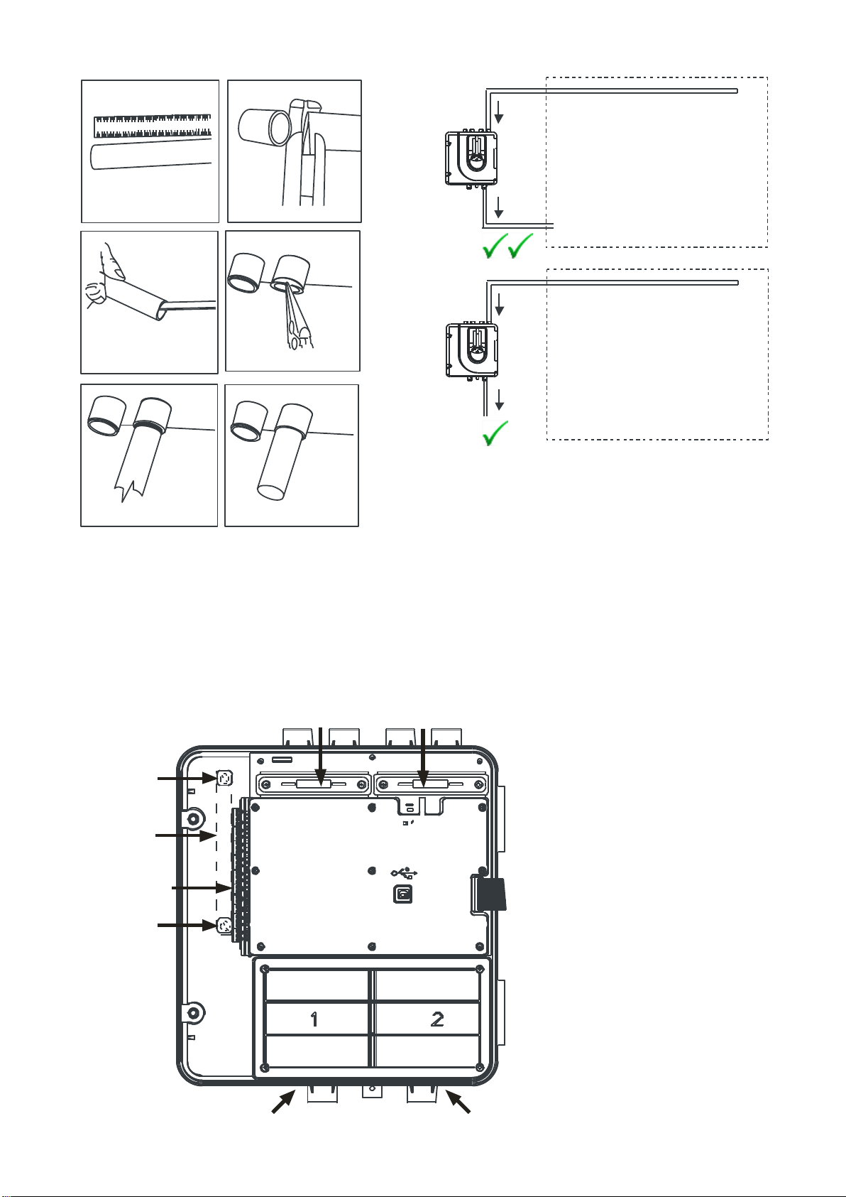
PC connectivity is provided by an on-board USB B socket located centrally between the filter and the sensor
(refer to Figure 10 on Page 4). The USB interface allows access to a range of additional options, via the PipeIQ
application software, when connected to a PC. The USB connecting cable should be removed during normal
operation.
PipeIQ™ QUICK START INSTRUCTIONS
Overview: the PipeIQ software program is a convenient and powerful Windows® based application used to
quickly and accurately design pipe networks, generate configuration parameters for correct set-up and operation,
and facilitate commissioning and monitoring of the performance of FAAST LT Aspiration devices.
PipeIQ provides a graphical interface on a PC to:
• design and verify the performance of pipe network solutions.
• draw and view pipe designs in 3D
• configure the design parameters to suit local fire codes and standards.
• generate Pipe Layouts, BOMs, Configuration and Event Log Reports.
• test relays and Alarms, perform smoke test, and fans speed test
• retrieve and view logs in graph and tabular form
• control, test and monitor FAAST aspirating detectors.
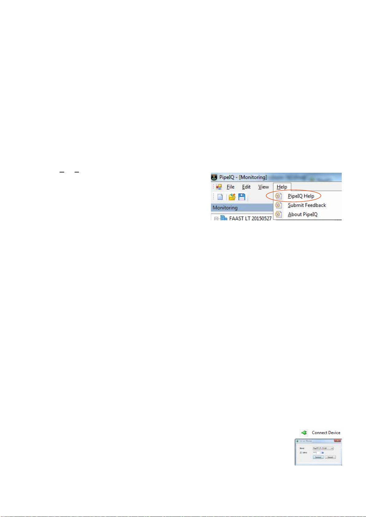
A comprehensive Help Menu is available from the Menu Bar to guide the user through the different windows and
options : Help\PipeIQ Help.
The contents have a detailed index and a versatile search
facility to locate relevant topics.
Refer to I56-3888-001P FAAST LT PipeIQ Configuration
Guide for detailed instructions on configuring the FAAST LT
ASD detector
QUIK-START GUIDE
Equipment Required:
a) USB printer Cable USB 2.0 Type Male A to USB Type B Male. The FAAST LT uses a USB 2.0 type B socket.
b) PC with PipeIQ v2 or greater installed. The PipeIQ software is available for download from:
https://www.systemsensor.com/en-us/Pages/PipeIQ.aspx
You will be requested to register and login to the site to gain access to the software.
Caution: DO NOT use PipeIQLT or PipeIQ v1, available from the CD included with the FAAST detector or
available from : http://www.faast-detection.com/contact-us/download-pipeiq/
Connection to the FAAST LT:
a) Open PipeIQ (v2 or greater) on the PC –by default, PipeIQ opens in Configuration mode
b) Open a project file (*.mdf) to continue –use one of the following methods:
i. open an existing project configuration (*.mdf) file for the FAAST LT or
ii. start a New Config and add a FAAST LT detector of the type to be installed or being maintained
- save this Config file : use a filename which will readily relate to the detector under test
eg. FL2011EI-3 20150528 for the third Single Channel, Single Sensor FAAST LT detector on the site
c) Power up the FAAST LT - wait until the FAAST has completed initialisation (the Power LED turns green)
d) Log the FAAST LT into Maintenance Mode
i. press and hold RESET until the Low Flow indicator turns yellow, then green.
ii. release RESET and the FAULT indicator switches on green. The left Flow indicator blinks green indicating
the device is ready for the first digit
iii. press DISABLE to increment the LEDs 1…9; press TEST to select the first digit. (Default Password = 3111)
The first flashing Airflow LED will turn solid green to indicate the first digit has been selected and the next
segment will begin to flash indicating the next digit is ready to be selected. When the 4th digit is selected,
all 4 airflow segments turn off. If the password is accepted the FAULT indicator remains green and the unit
enters Maintenance mode. If the password is incorrect the FAULT indicator flashes yellow and the unit
remains in Normal mode.
iv. if there is no activity in Maintenance mode for 5 minutes (default), the FAULT indicator blinks green for 15
secs and then the unit returns to the Normal state
e) Open the FAAST LT door and connect the USB connector from the PC
f) select View \ Configuration from the Menu bar, right click the detector configured in
Section b) above and then select Connect Device
g) Select the detector at the appropriate COM Port. select Admin and enter the password,
then Connect:
h) Align the detector and PC Configurations by either:
i. b) i. above. Right click the device and select Send Configuration to a new detector or a
detector which is being updated
ii. b) ii. above. Right click the device and select Get Configuration for an existing detector being maintained

© Pertronic Industries Ltd 11 FAAST LT Stand-Alone Installation & Maintenance Guide Iss 1.0, 201701
Section C : CONFIGURING FAAST LT in PipeIQ
The following tables identify the parameters which are configurable on the FAAST LT devices. Review all
parameters to ensure they are appropriate, taking particular care to ensure the parameters in blue are correct
General Configurable Parameters:
The General Configurable Parameters enables the FAAST parameters to be edited and modified.
The device configuration page of PipeIQ consists of the following parameter tabs.
General
Channels and Sensors
Alarms and Relays
To restore the default parameters:
a) Select Configuration on the left pane.
b) Click the device. By default, the General tab appears.
c) Click the Restore Default Values button.
All the configuration parameters are restored with default values.
General:
To configure the device, set the General parameters in the General tab.
a) Select Configuration on the left pane.
b) Click the device. By default, the General tab appears.
Specify the following details:
Fields
Description
General Parameters
Pressure
Specify the atmospheric pressure (in Pascal).
Both supplies
monitored
By default, the first power supply is monitored to signal a low power.
Select Yes to monitor the second power supply.
Power Restart Alert
Alert for
The device signals the power restart alert for this period.
Alert till Reset
Select to enable alert until the reset is performed.
Disable
Select to disable the power restart alert.
Trend Log
Log for every
Specify the time interval (in minutes) used by the device to log its state.
Disable
Select to disable the trend log.
c) Save to implement the changes.
d) It is prudent to monitor detector performance by turning Trend Log ON for an appropriate period (1 week??),
then review the log to verify the settings are appropriate for the site (refer to Section E2f, System Check):
(i) Sensitivity: note the difference between the background particulate level and the Sensitivity Levels to
ensure the configured Alert/Alarm levels are appropriate and note variations in background particulate
levels which may generate nuisance Alerts/Alarms. Adjust the Alert/Alarm Sensitivity Levels, to suit.
(ii) Flow Rate: confirm the flow(s) for each channel to verify they match the calculated values and to identify
variations resulting from environmental factors –AHU operation, doors opening and closing, etc.

© Pertronic Industries Ltd 12 FAAST LT Stand-Alone Installation & Maintenance Guide Iss 1.0, 201701
Channels and Sensors:
To configure the device, set the parameters in the Channels and Sensors tab.
a) Select Configuration on the left pane.
b) Click the device. The General parameters configuration screen appears in the right pane.
c) Select the Channels and Sensors tab.
Specify the following details.
Fields
Description
Channels:
Enable the required Channel(s). The options are:
Channel 1
Channel 2
Note:
The following fields are configured based on the specific Channel which is selected
Label:
Specify a label to identify the zones served by the channels
Alarm is Latched
Select either of the following:
Yes: The device retains the Alarm relay activated state until a Reset is performed
No: The device automatically de-activates the relay
Fan Speed Mode:
Select either of the following:
Auto: the device automatically sets the fan speed, at every power ON, to reach the
configured reference flow
Manual: the device uses the configured manual speed.
Fan Speed:
Drag and set the speed scale for the fan
Note:
The fan speed set here is considered for the calculations of the built network when the
fan speed mode is selected as Manual
Reference Flow:
Specify the flow value in litre per minute (l/min)
Filter Due Date:
Specify the due date for the air filters. The device displays a filter fault after the due date
Sensors:
The Sensor Enabled state is based on the Channel Enabled state:
Sensor 1 enabled
Sensor 2 enabled
Note: either of the two Sensors may be disabled if the device has one channel and two
sensors
Sensor blinking
replicated:
Select either of the following.
Yes: The channel alarm LED blinks a steady green when the sensor is polled
No: The channel alarm LED does not blink when the sensor is polled
Common
chamber:
Select either of the following.
Yes: Alarm is set when one sensor is in the Alarm condition
No: Alarm is set when both the sensors are in the Alarm condition
d) Save to implement the changes.
To configure the Advanced parameters, refer to Advanced Configurable Parameters

© Pertronic Industries Ltd 13 FAAST LT Stand-Alone Installation & Maintenance Guide Iss 1.0, 201701
Alarms and Relays:
To configure the device, set the parameters in the Alarms and Relays tab.
a) Select Configuration on the left pane.
b) Click the device. The General parameters configuration screen appears in the right pane.
c) Select the Alarms and Relays tab.
Fields
Description
Automatic Sounder Turn Off
Turn off sounder after:
Select the cut-off time. When the Alarm condition is reached, the sounder
automatically turns off after the specified cut-off time
Disable:
Select to disable the automatic sounder turn off
Also, specify the following details
Alarm Delay:
Specify the alarm delay. When the alarm condition is reached, the alarm relay
activation is delayed until the specified period. The delay is reset if the alarm
condition is left
Flow Fault Delay:
Specify the flow fault delay. When the flow condition reaches low or high, the flow
fault is delayed until the specified period. The delay is reset if the fault condition is
left
General Fault Delay:
Specify the fault relay delay. When there is a fault condition, the device waits for this
delay period before giving fault and set general fault relay. The delay is reset if the
fault condition is left
General Fault Latched:
Select either of the following:
Yes: The device retains the fault relay activated until a reset is performed.
No: The device automatically deactivates the relay
Auxiliary Relay used
for Channel 2 Fault:
Select either of the following:
Yes: The device activates
the general fault relay for the faults of channel 1 and faults common to
both channels.
the auxiliary fault relay for faults of channel 2 and for the faults/alerts
configured to activate auxiliary relay.
No: The auxiliary relay is not used for the channel 2 fault
Auxiliary Relay is
Latched:
Select either of the following:
Yes: The device retains the auxiliary relay until a reset is performed.
No: The device automatically deactivates the relay
Events Triggering
Auxiliary Relay:
Select to trigger the activation of the auxiliary relay
Auxiliary Relay set on
Temperature Alert:
Select to trigger the activation of the auxiliary relay due to temperature alert
Auxiliary Relay set
on External Input In
Not Normal State:
Select to trigger the activation of the auxiliary relay due to external input
Auxiliary Relay set
on Low Power
Alert/High Power
Fault:
Select to trigger the activation of the auxiliary relay due to low power alert
Auxiliary Relay set
on Flow Fault:
Select to trigger the activation of the auxiliary relay due to flow fault
Auxiliary relay set
on Sensor
Communication
Fault or Low
Chamber Fault:
Select to trigger the activation of the auxiliary relay due to sensor communication
fault
Auxiliary Relay set
on Power Restart
Alert:
Select to trigger the activation of the auxiliary relay due to power restart alert
d) Save to implement the changes.

© Pertronic Industries Ltd 14 FAAST LT Stand-Alone Installation & Maintenance Guide Iss 1.0, 201701
Advanced Configurable Parameters:
The Advanced Configurable Parameters allows FAAST parameters to be edited and modified.
The Advanced tab consists of the following parameter tabs.
General
Date and Time - enabled only for FL01nnE Standalone devices
Before configuring the Advanced parameters, ensure that the General Parameters are configured
General:
To configure the device, set the advanced parameters in the Advanced tab.
a) Select Configuration on the left pane.
b) Click the device. By default, the General tab appears
c) Select Advanced. The Advanced Parameters dialog box appears
In the General tab, specify the following details:
d) Save to implement the changes
Fields
Description
Maintenance
Password:
Click Change to modify the existing password.
The password should have four characters and must be with in the range of 1-9 digits.
Disable Time:
Specify the time for the device to stop working. During this time, all the alarms and
faults are not reported. When the set time is complete, the device goes to maintenance
state
Maintenance
Timeout:
Specify the maintenance timeout. The device returns to the normal state after the
timeout
Daylight Saving
Yes:
Select Yes to automatically change the device real time clock date when the date is in
the daylight saving period (1 hour is added).
No:
Select No to disable the daylight saving option.
Auto:
Select Auto to automatically set the start date as last Sunday of March 02:00 and the
end date as the last Sunday of October 02:00
Start Date:
Select the start date of daylight saving period
End Date:
Select the end date of daylight saving period
Note:
The Start and End Date option is enabled only when the daylight saving is set as Yes
External Input
External Input Normal State
Open:
Specifies Open as the normal state of the external input line. No actions are
triggered in this state
Short:
Specifies Short as the normal state of the external input line. No actions are
triggered in this state
Event Triggered by External Input
External input
triggers fault:
Select to specify the action triggered by the device when external input line is not
defined in normal state
External input
silences sounders:
Select to specify the action triggered by the device when external input line is not
defined in normal state
External input reset
device:
Select to specify the action triggered by the device when external input line is not
defined in normal state
External input
disables device:
Select to specify the action triggered by the device when external input line is not
defined in normal state
None:
Select to specify none of the events
FAAST LT
Disabling Time:
Specify the Disable period used by the device

© Pertronic Industries Ltd 15 FAAST LT Stand-Alone Installation & Maintenance Guide Iss 1.0, 201701
Sensor:
To configure the device, set the advanced parameters in the Advanced tab.
a) Select Configuration on the left pane.
b) Click the device. By default, the General tab appears
c) Select Advanced. The Advanced Parameters dialog box appears
In the Sensor tab, specify the following details:
d) Click Apply to implement the changes
e) Click OK. The main page appears
Note: Click Cancel to return to the main page without implementing changes
Fields
Description
Sensor Alarms:
Pre-Alarm Level:
Select the Pre-Alarm Sensitivity level from the drop-down list.
The level can be selected on a scale of 1-9 for Sensor 1 and Sensor 2
Alarm Level:
Select the Alarm Sensitivity level from the drop-down list
The level can be selected on a scale of 1-9 for Sensor 1 and Sensor 2
Notes:
a) The Pre-Alarm and Alarm Levels to be used are determined after the pipe network
Design has been completed and the system is correctly balanced for Flow and
Transport Time.
- determine the Sensitivity required at each Sampling Point, then use the Alarm
Level as determined during the PipeIQ Design Calculation
- although levels 1-9 are available, Alarm level is likely to be 3-5 for SFD, while Pre-
Alarm will be a lower (more sensitive) number : 1 to Alarm-1
b) Day-Night mode enabled: sets different Alarm and Pre-Alarm levels for Day and
Night. When Day-Night mode is enabled, the Day/Night Pre-Alarm and Alarm
fields are enabled under Sensor Alarms
Day-Night Mode Enabled: provides for different sensitivity settings for Day and Night (optional)
Day Start Time:
Select the Start Time of the day
Day End Time:
Select the End Time of the day
Night Mode Interval:
Specifies the Start and End Time of the Night Mode. The interval value is calculated
based on the Day Start and End time. This is a read-only field
Sensor Alarms:
Day Pre-Alarm Level:
Select the Day Pre-Alarm Level from the drop-down list.
The level can be selected on a scale of 1-9 for Sensor 1 and Sensor 2
Day Alarm Level:
Select the Day Alarm Level from the drop-down list.
The level can be selected on a scale of 1-9 for Sensor 1 and Sensor 2
Night Pre-Alarm
Level:
Select the Night Pre-Alarm Level from the drop-down list.
The level can be selected on a scale of 1-9 for Sensor 1 and Sensor 2
Night Alarm Level:
Select the Night Pre-Alarm Level from the drop-down list.
The level can be selected on a scale of 1-9 for Sensor 1 and Sensor 2
Pre-Alarm:
Pre-Alarm Delay:
Specify the Pre-Alarm Delay Time.
The device waits for this delay period before giving Pre-Alarm
Pre-Alarm and Alarm
are in Cascade:
When the Alarm Cascade option is selected and the Alarm smoke level is reached,
the device passes through the Pre-Alarm condition and the related delay.
When the Alarm Cascade option is not selected, Pre-Alarm delay is skipped and the
Alarm Delay is started.
Sounder Activation Mode:
Pre-Alarm:
The device activates Sounder relay when the Pre-Alarm is reached
Alarm:
The device activates Sounder relay when the Alarm is reached

© Pertronic Industries Ltd 16 FAAST LT Stand-Alone Installation & Maintenance Guide Iss 1.0, 201701
Analogue Addressable - F100 / F120:
FAAST LT Stand-Alone (FL01nnE)
Type: - the FAAST LT Stand-Alone detector provides clean-contact relay outputs - these generally
connect to Loop Addressable Input Modules (eg M500MB or similar) to connect to an F100 /
F120 panel
- all activation relays are configured as TYPE = SW (Module)
Alarm: - terminate with 47K EOL to Normalise (10K for Loop Responder –refer below)
- is generally configured to activate the Fire (F100) or Brigade (F120) relay.
Pre-Alarm: - terminate with 47K EOL to Normalise (10K for Loop Responder –refer below)
- relay is configured as required
Defect: - switch a short-circuit to activate a Defect (for Loop Responder –refer below)
- may be connected across the ALARM or PRE-ALARM module
Sensitivity: - the FAAST LT detector Threshold Levels are configured at the detector:
Configuration \ Advanced \ Sensor
- two Activations Levels are available: ALARM and PRE-ALARM
- each level provides individual Threshold Levels (sensitivity) for Day and Night (optional) use
Conventional - F16e / F4 / Loop Responder (NZS4512:2010):
FAAST LT Stand-Alone (FL01nnE)
Sensitivity: - the FAAST LT detector Threshold Levels are configured at the detector:
Configuration \ Advanced \ Sensor
- two Activations Levels are available: ALARM and PRE-ALARM
- each level provides individual Threshold Levels (sensitivity) for Day and Night (optional) use
- clean-contact relay outputs are provided for each Activation Threshold - these connect to one or
more individual circuits, depending upon the number of Activation Levels required
Alarm: - terminate with a 10K EOL resistor to Normalise the circuit
- switch a 470R resistor to activate as a Smoke Alarm or switch a 180R resistor to activate as a
Heat Alarm
Pre-Alarm: - terminate with a 10K EOL resistor to Normalise the circuit
- switch a 470R resistor to activate as a Smoke Alarm
- ALARM and PRE-ALARM may be combined on a single circuit on the F16e provided the circuit
is configured for Residential mode and the ALARM relay switches the 180R resistor (Heat Alarm)
and the PRE-ALARM relay switches the 470R resistor (Smoke Alarm)
Defect: - switch a 1K8 resistor or an open or short-circuit to activate a Defect.
Conventional - F16e / F16 / F4 / Loop Responder (NZS4512:1997):
FAAST LT Stand-Alone (FL01nnE)
Sensitivity: - the FAAST LT detector Threshold Levels are configured at the detector:
Configuration \ Advanced \ Sensor
- two Activations Levels are available: ALARM and PRE-ALARM
- each level provides individual Threshold Levels (sensitivity) for Day and Night (optional) use
- clean-contact relay outputs are provided for each Activation Threshold - these connect to one or
more individual circuits, depending upon the number of Activation Levels required
Alarm: - terminate with a 10K EOL resistor to Normalise the circuit
- switch a 470R resistor to activate as a Smoke Alarm or switch a 180R resistor or open-circuit to
activate as a Heat Alarm
Pre-Alarm: - terminate with a 10K EOL resistor to Normalise the circuit
- switch a 470R resistor to activate as a Smoke Alarm
- ALARM and PRE-ALARM may be combined on a single circuit on the F16 provided the circuit is
configured for Apartment mode and the ALARM relay switches the 180R resistor or open-circuit
(Heat Alarm) and the PRE-ALARM relay switches the 470R resistor (Smoke Alarm)
Defect: - switch a 1K8 resistor or a short-circuit to activate a Defect.
F16 - functionality of a FAAST detector with an F16 is limited because of the restrictions of the F16 in
Apartment mode
BELL
Link
FIRE
Link
Apartment
Mode
Bell
relay
Brigade
relay
Fire
LED
Zone
LED
Latch
Clear
In
Out
Smoke
Yes
No
No
Yes
Yes
Ext BCO
Reset
Heat
Yes
Yes
Yes
Yes
Yes

© Pertronic Industries Ltd 17 FAAST LT Stand-Alone Installation & Maintenance Guide Iss 1.0, 201701
Section D : MONITORING FAAST LT using PipeIQ
This section identifies options for testing the FAAST LT and monitoring its environment:
Actions:
The PipeIQ™ Actions tab enables:
Test Relays
Smoke Test
Test Fan speed
Alarms Test
Sounder
Restart
FAAST LT Clock
Operating Hours
Reset
D1a Test Relays: to test relays
a. Click Monitoring on the left pane.
b. Select the device to set the actions. The Actions tab appears on the right pane.
c. Under Test Relays, set the following relays.
i. Alarm Relays:
Under Alarm 1 and Alarm 2, click the status button to activate or deactivate the alarm.
ii. Pre-Alarm Relays
Under Pre-Alarm 1 and Pre-Alarm 2, click the status button to activate or deactivate the Pre-Alarm.
iii. Sounder Relays
Under Sounder 1 and Sounder 2, click the status button to activate or deactivate the sounder relay.
iv. Fault Relays
Under Fault and Aux Fault, click the status button to activate or deactivate the fault relay
Note: Click Refresh to obtain the current state of all the relays
D1b Smoke Test: to perform Smoke Tests
a. Click Monitoring on the left pane.
b. Select the device to set the actions. The Actions tab appears on the right pane.
c. Under Smoke Test, set the time for the following two options:
i. Start at a set time:
Select Start at and select the time to schedule a start time for the smoke test
Click Schedule
ii. Start now
Select Now
Click Start
The Alarm Time (mins/secs) specifies the measured time between the insertion of smoke and
activation of an Alarm
The Transport Time (mins/secs) specifies the measured time between the insertion of smoke into
the pipe system and the time taken for the smoke particles to reach the detector.
The measurement is stopped when the smoke level reaches Level 1.
Click Stop.
D1c Test Fan Speed: to test Fan Speeds
a. Click Monitoring on the left pane.
b. Select the device to set the actions. The Actions tab appears on the right pane.
c. Under Test Fans Speed, set the channel speed:
i. Set the Channel 1 speed on the scale
ii. Click Test Fan 1
The Fan 1 speed rate is checked and the change in Flowrate 1 is displayed
iii. Click Stop
Note: Repeat Steps i. through iii. to set the speed for Channel 2

© Pertronic Industries Ltd 18 FAAST LT Stand-Alone Installation & Maintenance Guide Iss 1.0, 201701
D1d Alarms Test: to test Channel Alarms
a. Click Monitoring on the left pane.
b. Select the device to set the actions. The Actions tab appears on the right pane.
c. Under Test Channels Alarm, the following options can be set:
i. Test Channel 1 Alarm: click to test the Channel 1 Alarm
ii. Test Channel 2 Alarm: click to test the Channel 2 Alarm
iii. Test Both Channels Alarm: click to simultaneously test both the channels Alarm
D1e Sounder: to set Sounder
a. Click Monitoring on the left pane.
b. Select the device to set the actions. The Actions tab appears on the right pane.
c. Under Sounder, the following options can be set:
i. Silence Sounder 1: click to silence Sounder 1
ii. Silence Sounder 2: click to silence Sounder 2
iii. Silence Sounder 1,2:: click to simultaneously silence Sounders 1 and 2
D1f Restart: to restart
a. Click Monitoring on the left pane.
b. Select the device to set the actions. The Actions tab appears on the right pane.
c. Under Restart, set the following options:
i. Normal: select to restart the device in Normal mode
ii. Maintenance: select to restart the device in Maintenance mode
d. Click Set to apply the restart settings
D1g FAAST LT Clock: to set the FAAST Clock
a. Click Monitoring on the left pane.
b. Select the device to set the actions. The Actions tab appears on the right pane.
c. Under FAAST Clock, obtain or modify the clock settings:
i. Get: click to obtain the current device time
ii. Change: click Change FAAST Clock, (which appears as a hyperlink) to change the
clock
D1h Operating Hours: to obtain the Operating Hours
a. Click Monitoring on the left pane.
b. Select the device to set the actions. The Actions tab appears on the right pane.
c. Under Operating Hours, obtain the number of hours the device has operated:
i. Get: click to obtain the operating hours of the device
ii. Clear: click to clear the operating hours for the device
D1i Reset: to Reset the device
a. Click Monitoring on the left pane.
b. Select the device to set the actions. The Actions tab appears on the right pane.
c. Click Reset to reset the device

© Pertronic Industries Ltd 19 FAAST LT Stand-Alone Installation & Maintenance Guide Iss 1.0, 201701
D2. Log View:
The PipeIQ™ Log view provides:
Graph views
Device Logs : read and clear
Generate Reports
D2a View Graphs
a) Click Monitoring on the left pane.
b) Select the device to view the events. The Actions tab appears on the right pane.
c) In the Log tab, click the Graphs tab.
i. Under Trend Graph: Parameters, select from the following parameters:
Flow Rate 1
Flow Rate 2
Temperature
Sensor1 Smoke Concentration
Sensor2 Smoke Concentration
Note: just two parameters can be viewed at one time on the Trend Graph
ii. Under Event Graph: Event Groups, select graphs for the listed event groups.
D2b View Events
a) Click Monitoring on the left pane.
b) Select the device to view the events. The Actions tab appears on the right pane.
c) in the Log tab, click the Events List tab.
i. Select Show All Events to view all the events of the device.
ii. Select Period to view all the events within the specified date.
From and To dates are available from the drop-down calendar.
iii. Click Show. The list of events appears.
Note: the Show Last drop-down list to select the latest 20/50/100/500 events
Below the list of events:
click First, Previous, Next and Last to view records present in multiple pages
events are displayed with the oldest event first
select the Page Size and Page No from the drop-down list
d) Click Read Device Logs to retrieve and read all the logs present in the device.
the Event Log is not dynamic. Select Read Device Logs to update the log with recent events
e) Click Reset Zoom to reset the zoom settings.
f) Click Clear Log to clear the log data.
g) Click Generate Report to generate a report for the selected events
the Report may be saved in one of three formats:
*.pdf
*.xls spreadsheet
*.doc document
An xls spreadsheet allows the events to be sorted and edited

© Pertronic Industries Ltd 20 FAAST LT Stand-Alone Installation & Maintenance Guide Iss 1.0, 201701
Section E : SYSTEM TEST AND COMMISSIONING:
E1. Ensure the following items are available:
a) FAAST System Pipe Layout Report:- allows the measured values to be referenced to the values calculated in
PipeIQ.
b) FAAST System Bill of Materials Report
c) As-built Installation Drawings
d) Smoke Pen or other source of smoke with a particulate life cycle of greater than 120 seconds
e) Timer or stop-watch - to measure the maximum Transport Time
f) Blue-Tak or similar to block holes during Flow tests
g) Locally Required Forms
E2. Commissioning and Handover (reference: FIA Code of Practice for ASDs, Issue 3, Feb 2012)
E2a Commission Testing
The Commissioning Tests to be performed depend on the ASD system application but should be carried out only
when the building is in its normal, intended running state. Appropriate commissioning tests should also be
performed after modifications and/or additions to the ASD system.
Commissioning
The commissioning process has several stages which should be performed, recorded and checked as necessary:
•Inspection of Installation –verify conformity to design, definition of system (see section 5) including
mechanical and electrical installation.
•Power Up/Configuration –required checks and configuration
•Commissioning Tests –to include mechanical, functional and performance testing.
•Signalling - to verify the connections between the ASD and other connected systems (e.g. FAP, BMS).
•System Check - to verify the detector settings are appropriate for the site
•System Handover –include relevant documentation and recorded drawings.
E2b Inspection of Installation
Inspect the installation to confirm that it has been designed and installed correctly for the application and
conforms to the design documentation - in particular;
ASD used to replace point-type detectors (Class C) - ensure the installation (particularly Sample Point spacing)
conforms to the relevant standard (e.g. NZS4512:2010) and the ASD Sensitivity/Alarm thresholds are correctly
set to ensure that the sensitivity of individual holes meets the minimum performance requirements for
individual points. Note that this may require reference to the approval compliance notes for the particular ASD
system and should also take into account any potential automatic adjustments of the Sensitivity/Threshold
settings, which may occur after commissioning.
ASD used for high and enhanced sensitivity (Class A/B) - ensure that the installation conforms to the design
specification (eg. if necessary, measure the air velocities in the protected area to ensure that the design
spacing is appropriate.
ASD used as a Primary Sampling System (refer to Table: ‘Sensitivity Class vs Detection Requirements’on
page 26), ensure the pipe and sample points are installed correctly onto the Air Handling Unit (AHU) within the
airflow. If monitoring more than one AHU, it is important to ensure different running speeds do not cause an
unbalanced airflow in the pipe, which may affect ASD performance.
ASD used for other installations (cabinet, duct work or other specialist protection) - confirm that the ASD
system is in accordance with the design.
Perform a thorough inspection of the mechanical and electrical installation - include;
pipe network including correct supports.
clear identification of Sampling Points.
no obstructions to Sampling Points or remote capillaries.
all internal and external electrical wiring has been installed correctly.
power supplies are correctly rated and provide the correct emergency battery standby period.
correct hole position and sizes.
Before the ASD is powered up, it is very important to check that the pipe is clear of any foreign articles eg. swarf,
dust, etc. that will impede or stop the ASD performance.
E2c Power Up/Configuration
It is very important that the ASD manufacturer’s technical documentation is followed during system set-up. If there
is any doubt refer back to the manufacturer for clarification.
The system should be powered up in accordance with the manufacturer’s recommendations. Prior to carrying out
any functional and performance tests the ASD equipment should be configured for:
•Fire signal Alarm thresholds and detector sensitivity settings to give required sampling point sensitivity.
•Alarm and Fault delay periods.
•Airflow parameters.
•any other defined parameters.
This manual suits for next models
2
Table of contents
Other Pertronic Fire Alarm manuals
Popular Fire Alarm manuals by other brands

Dorgard
Dorgard DG1328-FP operating guide

Siemens
Siemens FP-11 FirePrint introduction

Awex
Awex MCP / ROP 21 Assembly instructions

Teknim
Teknim TWS-1815 Installation & user manual

LY International Electronics
LY International Electronics M-9000 Series user manual

First Alert
First Alert SMOKE AND FIRE* ALARM user manual