Página: 6 / 12 DW-PT
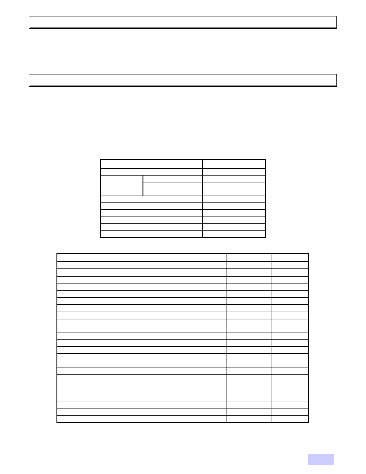
Description of the display indicators.
Luminous indicators
POWER SUPPLY / LOW
BATTERY
If the luminous indicator is fixed it indicates that the equipment is ON.
If blinking indicates low battery level.
Prog
PROGRAMMING The equipment is in some programming option.
Error
ERROR / OUTPUT ALARM The equipment has detected an error during its operation.
STABLE WEIGHT It indicates that the weight on the scale is stable, without oscillations.
WEIGHT IN ZERO ZONE It lights when the scale is in zero zone.
NET
NET / GROSS When lights indicates that the current value of weight is the NET. It will fade
when the GROSS weight arrives to ZERO and there is not a FIXED TARE.
TARE It lights when the equipment has a FIXED TARE that can be deleted pressing
the TARE key.
PT
PRESET TARE It indicates that the equipment has already a FIXED TARE that can only be
eliminated pressing the key TARE again.
PIECES Piece-counter display mode.
TOTALIZER Totalizer display mode (weight or pieces).
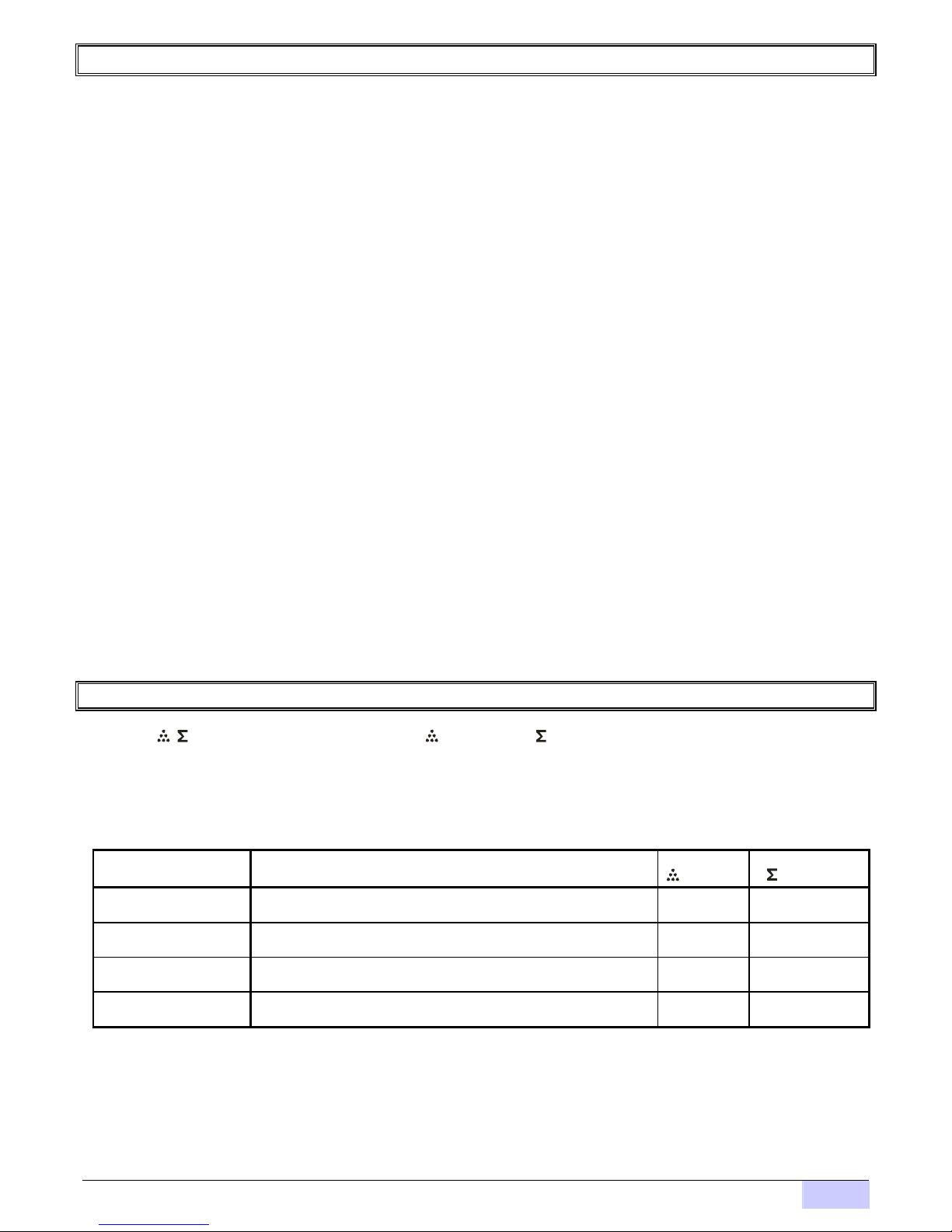
Keyboard’s description.
Keys
ESCAPE: This key is used to navigate trough the menus when programming.
/
PIECES / TOTALIZER: If [Prog] is disabled changes sequentially among weight, pieces, weight totalizer and
number of pieces totalizer.
UP: This key is used to navigate trough the menus when programming.
ZERO: If [Prog] is disabled forces a new ZERO of the indicator, and later will light.
In the totalizer mode allows to set to zero the accumulated value of weight (in case that the totalizer of weight is
activated) or the accumulated value of pieces (in case that the totalizer of pieces is activated).
DOWN: This key is used to navigate trough the menus when programming.
PRINT: If [Prog] is disabled totalizes the operation or the number of pieces and prints a ticket.
RIGHT: This key is used to navigate trough the menus when programming.
TARE: If [Prog] is disabled, activates the indicator’s TARE function. The first time activates
NET
, the second
time activates , and a third pressing disables TARE.
ENTER: This key is used to navigate trough the menus when programming.
MENU
MENU: If [Prog] is disabled, the MENU key allows to access to all the parameters of the indicator.
Error messages.
General:
Err 66 Input value too small.
Err 67 Input value too high.
err 10 Serial channel testing error.
ERR 11 Serial channel testing error.
ERR 30 There are no totals to print.
ERR 31 It’s not possible to store the operation to reprint tickets.
ERR 32 Print timeout in certain protocols.
Weight:
Error description Possible causes.
Err 12 Over 2 Overflow. Scale’s capacity
exceeded. Scale’s capacity or load cell bad dimensioned.
Err 13 Over 1 AD converter overflow. Check the connection of the load cell or load cell bad
dimensioned.
ERR 14 Unde 1 AD converter underflow. Check the connection of the load cell or load cell bad
dimensioned.